manuals.online logo
Brands
  1. Home
  2. •
  3. Brands
  4. •
  5. Nice
  6. •
  7. Security Sensor
  8. •
  9. Nice LP21 User manual

Nice LP21 User manual

LP21/LP22
LP21/LP22 Quick start guide 1.1 EN 1|4
Sensors
EN - Quick start guide
NOTE
Read the operating instructions
You can find detailed instructions and comprehensive information in
the full user manual for the product. This document is available on the
www.niceforyou.com.
Read and keep instructions
Read this document before you use the product for the first time, and
keep it in a safe place for future reference.
Maintenance and repairs
No maintenance or servicing are required for this product.
In the event of malfunctions and faults, please contact the vendor or
the manufacturer.
WARNING
Improper use
The device is subject to the manufacturer’s guarantee conditions valid
at the time of purchase. The manufacturer shall not accept any
responsibility for incorrect manual or automatic parameter settings
performed on a device or the inappropriate use of a device.
Improper repairs
Repairs may only be performed by the manufacturer. Failure to comply
results in endangering the safety of the device and renders the
warranty null and void.
Permitted power sources
The power supply must meet the requirements for safety extra-low
voltage (SELV).
Essential safety equipment
The device may not be used as a safety component as defined by the
Machinery Directive 2006/42/EG, the Construction Products
Regulation 305/2011/EU or other safety regulations. Systems posing a
threat of danger require additional safety equipment.
1 Product overview
Product components
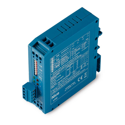
LP22/LP21 Traffic Detector
Plug-in terminal blocks (1 x supply, 1 x loop, 2 x relays)
Quick guide
Tab. 1: Scope of delivery
Fig. 1: LP21/LP22 product image
Index
Component
1 Terminal block output 1:
• Relay 1 (yellow)
2 Terminal block loop channel input (orange)
3 Reset button
4 USB interface
5 DIP switch 2 (LP22)
6 LED‘s loop channel 1 (red + blue) LP21
LED‘s loop channel 2 (red + blue) LP22
7 DIP switch 1
8 LED‘s loop channel 1 (red + blue) LP22
9 Terminal block AC/DC (blue)
10 Terminal block output 2:
• Relay 2 (red)
11 Mounting device for DIN rail
Tab. 2: LP21/LP22 component list
Technical data
Dimensions 22.5 x 79.0 x 81.0 mm (W x H x L
without terminals)
Power supply (1x blue) 10 – 30 VDC / 10 – 26 VAC, max. 2
W (SELV)
Protection type IP20
permissible operating
temperature
-37 – +70°C
relative humidity < 95 % (non-condensing)
Loop inputs (1x orange, 2-pole, 4-pole for double channel variants)
• max. inductivity range 20 - 700 µH (see note 1)
• recommended
inductivity range
100 – 300 µH
• operating frequency 30 - 130 kHz
• max. cable length 200 m
• max. internal resistance 20 Ω(including cable)
2 relays
(1x yellow + 1x red)
max. 48 V (AC/DC), 2 A, 60 W,
125 VA (SELV)
min. 1 mA / 5 V
Configuration switch 1
(all variants)
8-pole DIP switch
Configuration switch 2
(2 channel variants)
4-pole DIP switch
LED (1x blue + 1x red per loop channel)
Reset Push button
PC interface USB port, type mini AB
Tab. 3: Technical data
LP21/LP22
LP21/LP22 Quick start guide 1.1 EN 2|4
Sensors
NOTE
1. Restrictions with loop inductivity
For loop inductances outside the recommended range, only one
frequency level may be available. For very small loop
inductances, the maximum loop resistances are lower.
2 Product description
LP21/LP22 series Traffic Detectors are electronic sensors for inductive
recording of metallic objects. Vehicles, and depending on the device also
their model and the direction of movement, can be detected via up to two
induction loops.
Traffic detectors are operated in combination with a wide variety of
induction loops and control systems, such as frequency converters and
PLC control systems.
Areas of application may be facilities in the traffic engineering, door and
barrier control, or parking and tunnel surveillance sectors.
The LP21/LP22 Traffic Detector is intended for installation in a control
cabinet or a housing similar to a control cabinet.
LP21/LP22 series Traffic Detectors have the following product
characteristics:
• 1 loop channel (LP21) or 2 loop channels (LP22)
• 2 potential-free relay outputs
• 1 connection for power supply (24 volt AC/DC)
• 1 USB interface for diagnostics and expanded configuration
• 8-pole DIP switch, and 4-pole DIP switch (LP22) for configuration
• LEDs to indicate detector and loop status
• compact plastic housing for mounting on DIN rail in controller
cabinet
• galvanic isolation between loops and electronics
• automatic adjustment of the system after activation
• continuous readjustment of frequency drifts to suppress
environmental influences
• sensitivity independent of loop inductivity
• fixed signal hold times independent of the coverage rate of the loops
• direction detection with two loop channels (LP22)
• multiplexing prevents mutual interference between loop channels
(LP22)
Configuration options offered by LP21/LP22 series Vehicle Detectors
include:
• Switching between two frequency levels
• Output as presence, pulse or direction signal (2 channel variant)
• Choice of directional logic (2 channel version)
• Response threshold adjustable on each channel service program, in
4 steps on each DIP switch
• Hold time adjustable 5 minutes or infinitely with the DIP switch
3 Description of connections
3.1 Power supply
The detector can be operated with direct or alternating current, in
accordance with the requirement for safety extra-low voltage (SELV).
WARNING
Note the permissible power supply
Observe the technical data and safety instructions!
The connections on the blue terminal block allow for any desired polarity
of the power supply.
VCC POSITIVE
GND NEGATIVE
Fig. 2: Example of power supply (blue)
3.2 Loop inputs
Up to two analogue inputs for the induction loops on the terminal block
are located on the underside of the traffic detector. The terminal block is
either 2-pole (LP21) or 4-pole (LP22), depending on the number of
channels.
The induction loops are connected to the orange terminal blocks as
shown in the illustration.
L1a, L1b Induction loop channel 1
connections (LP21)
L2a, L2b Induction loop channel 2
connections (LP22)
(2 channel versions)
Fig. 3: Loop connections 1 channel or 2 channel versions (orange)
3.3 Signal outputs
3.3.1 Relay outputs with changeover contact
The outputs on the relay versions are constructed as changeover
contacts. This allows the contacts to be connected as normally closed
(NC) or as normally open (NO) contacts. The relays are potential-free and
suitable for many different types of switch.
The output signal of the relay can also be inverted (default). In this case,
when the power supply is turned on normally open contacts function as
normally closed contacts, and vice versa. This happens by switching
between open circuit and closed circuit principle.
Loop faults can also be interpreted as loop covered or as loop free.
LP21/LP22
LP21/LP22 Quick start guide 1.1 EN 3|4
Sensors
Status
Normally closed contact
(NC)
Normally open contact
(NO)
Open circuit
current
Closed
circuit
current
Open circuit
current
Closed
circuit
current
Voltage off
Detector
ready,
loop free
Loop
covered
Loop fault (default: loop covered)
Tab. 4: Relay switch status
The analogue outputs of the relay versions (-R24) are connected to the
red and yellow terminal blocks as shown in the following illustration.
NO 1/2 Normally open contact to output 1
or output 2
COM 1/2 Common contact to output 1 or
output 2
NC 1/2 Normally closed contact to output 1
or output 2
Fig. 4: Relay connection 1 (yellow) and 2 (red)
4 Description of functions
4.1 LED status indicators
The LEDs (light emitting diodes) on the front side display the state of the
loops and the detector.
There is a blue and red LED for each loop channel:
• the red LED provides information on the loop state
• the blue LED provides information on the detector state
• Position of the LEDs on the LP22: loop 1 upper left, loop 2 centre
Red
LED
Blue
LED Description of status
no power supply, detector inactive
detector ready, loop connected, no object detected
detector ready, loop connected, object detected
no loop connected, loop break, loop short-circuit
1 Hz
ready for operation following earlier, now rectified,
loop error
5 Hz
frequency readjustment is running
after the frequency readjustment, both LEDs
indicate the set loop frequency simultaneously in a
flashing code (see LED flashing code illustrated
example)
Tab. 5: LED signal colours
Key to LED symbols
lit up off
flashing frequency
LED flashing code
Fig. 5: LED indicates loop frequency
4.2 Reset button
The device is reset using the reset button on the front as follows:
Function Description Press
button
LED
reset /
readjustment
runs a frequency
readjustment and clears the
LED fault messages
1 second red LED
flashes
factory settings
resets the device to factory
settings (DIP switch default
settings)
5 seconds blue LED
flashes
Tab. 6: Reset functions
4.3 DIP switch settings
Parameter
Description
Sensitivity Switch-on threshold for signal output on covered
loop
Frequency level Frequency of the loop oscillating circuit in two
levels
Hold time Maximum duration of the output signal up to the
automatic readjustment of the loop channel
Output 2 signal
mode
Switching between continuous signal and pulse
signal at output 2
Output 2 switching
time
Time of signal output with activated pulse signal at
output 2
Output signal
inversion
Switching between open circuit and closed circuit
principle for signal outputs
Direction
detection
Switching between presence detection and
direction of travel detection for both outputs (2-
channel variants)
Direction logic Evaluation logic of the direction of travel according
to application on covered loop (see complete
operating manual!)
Tab. 7: Settings description
LP21/LP22
LP21/LP22 Quick start guide 1.1 EN 4|4
Sensors
The 1-channel variants have an 8-pole DIP switch for configuring the
detector.
DIP1
Designation
Function
1 Sense a loop 1 sensitivity
2 Sense b loop 1 sensitivity
3 Frequency frequency level
4 Hold Time hold time until readjustment
5 Output 2 output 2 signal mode
6 Edge 2 output 2 switching time
7 Inv. out 1 output 1 signal inversion
8 Inv. out 2 output 2 signal inversion
Tab. 8: DIP switch assignment (standard, 1-channel variants)
The 2-channel variants have an 8-pole and 4-pole DIP switch for
configuring the detector.
DIP1
Designation
Function
1 Sense 1a loop 1 sensitivity
2 Sense 1b loop 1 sensitivity
3 Sense 2a loop 2 sensitivity
4 Sense 2b loop 2 sensitivity
5 Frequency frequency level
6 Hold Time hold time until readjustment
7 Output 2 output 2 signal mode
8 Edge 2 output 2 switching time
Tab. 9: DIP switch 1 assignment (standard, 2-channel variants)
DIP2
Designation
Function
1 Dir. mode direction detection
2 Dir. logic direction logic
3 Inv. out 1 output 1 signal inversion
4 Inv. out 2 output 2 signal inversion
Tab. 10: DIP switch 2 assignment (standard, 2-channel variants)
The following parameters can be set with the DIP switch:
Parameter DIP switch Pos. Value
Sensitivity
Sense a
Sense b
ON
ON 0.01% (high)
Sense a
Sense b
OFF
ON 0.04%
Sense a
Sense b
ON
OFF 0.16%
Sense a
Sense b
OFF
OFF 0.64% (low)
Frequency level Frequency OFF
ON
low
high
Hold time Hold time OFF
ON
5 min
Infinite
Output 2 signal mode Output 2 OFF
ON
Continuous signal
Pulse signal
Output 2 switching time Edge 2 OFF
ON
on entering
on leaving
Parameter DIP switch Pos. Value
Output signal inversion Inv. Out 1/2 OFF
ON
inverted
not inverted
Direction detection Dir. Mode OFF
ON
Presence
Direction
Direction logic Dir. Logic OFF
ON
Continuous signal 2
Wrong-way driver 1
Tab. 11: Settings via DIP switch (default)
MANUFACTURER
NICE SPA
Street Callalta,1
31046 Oderzo (TV) Italia
MADE IN GERMANY

Other manuals for LP21

2

This manual suits for next models

1

Other Nice Security Sensor manuals

Nice Silentron Sil Bus 4080 Technical specifications

Nice

Nice Silentron Sil Bus 4080 Technical specifications

Nice LP22 Operating instructions

Nice

Nice LP22 Operating instructions

Nice CO Alarm-Control Technical specifications

Nice

Nice CO Alarm-Control Technical specifications

Nice MOONBUS MOFB Product manual

Nice

Nice MOONBUS MOFB Product manual

Nice HSDIM11 User manual

Nice

Nice HSDIM11 User manual

Nice HSDIM12 User manual

Nice

Nice HSDIM12 User manual

Nice Flood-Control Technical specifications

Nice

Nice Flood-Control Technical specifications

Nice Silentron Sil Bus Product manual

Nice

Nice Silentron Sil Bus Product manual

Nice Silentron Sil Bus 4081 Technical specifications

Nice

Nice Silentron Sil Bus 4081 Technical specifications

Nice F210B Product manual

Nice

Nice F210B Product manual

Nice HSDIM23 Technical specifications

Nice

Nice HSDIM23 Technical specifications

Nice HSDID11 User manual

Nice

Nice HSDID11 User manual

Nice LP21 Operating instructions

Nice

Nice LP21 Operating instructions

Nice EPMORB User manual

Nice

Nice EPMORB User manual

Nice HSDIM24 Technical specifications

Nice

Nice HSDIM24 Technical specifications

Nice MOONBUS MOFOB Technical specifications

Nice

Nice MOONBUS MOFOB Technical specifications

Nice F210 User manual

Nice

Nice F210 User manual

Nice Mhouse MAD6 User manual

Nice

Nice Mhouse MAD6 User manual

Nice HSDIM10 User manual

Nice

Nice HSDIM10 User manual

Nice Mhouse MAD3 Guide

Nice

Nice Mhouse MAD3 Guide

Nice HySecurity Hy5B User manual

Nice

Nice HySecurity Hy5B User manual

Nice 2GIG e Series User manual

Nice

Nice 2GIG e Series User manual

Nice LP21 User manual

Nice

Nice LP21 User manual

Popular Security Sensor manuals by other brands

Optex RXC-RST installation instructions

Optex

Optex RXC-RST installation instructions

Elitech CLD-100 instruction manual

Elitech

Elitech CLD-100 instruction manual

LST B524IEFT-1 Specification sheet

LST

LST B524IEFT-1 Specification sheet

Honeywell Home 5800PIR-RES Installation and setup guide

Honeywell Home

Honeywell Home 5800PIR-RES Installation and setup guide

Surface Concept MCPD18 manual

Surface Concept

Surface Concept MCPD18 manual

Bircher Reglomat Reflex ES user guide

Bircher Reglomat

Bircher Reglomat Reflex ES user guide

Monacor SMILE-16 operating instructions

Monacor

Monacor SMILE-16 operating instructions

Politec Sandor Plus Installation and commissioning manual

Politec

Politec Sandor Plus Installation and commissioning manual

mru 400DH user manual

mru

mru 400DH user manual

Pilz PSENslock PSEN sl-1.0p 1.1 VA operating instructions

Pilz

Pilz PSENslock PSEN sl-1.0p 1.1 VA operating instructions

Elko iNELS RFSF-100 Quick start quide

Elko

Elko iNELS RFSF-100 Quick start quide

Indyme Solutions, Inc. SmartDome DM9030SA Programming and installation instructions

Indyme Solutions, Inc.

Indyme Solutions, Inc. SmartDome DM9030SA Programming and installation instructions

Hytronik Dual Sense HIM16 manual

Hytronik

Hytronik Dual Sense HIM16 manual

Kaya Safety P-455 YO manual

Kaya Safety

Kaya Safety P-455 YO manual

Servodan niko PLUS 41-800 user guide

Servodan

Servodan niko PLUS 41-800 user guide

HESA HE400 quick start guide

HESA

HESA HE400 quick start guide

Time Gaurd TG115 Installation and operating instructions

Time Gaurd

Time Gaurd TG115 Installation and operating instructions

Knauer BlueShadow 50D user manual

Knauer

Knauer BlueShadow 50D user manual

manuals.online logo
manuals.online logoBrands
  • About & Mission
  • Contact us
  • Privacy Policy
  • Terms and Conditions

Copyright 2025 Manuals.Online. All Rights Reserved.