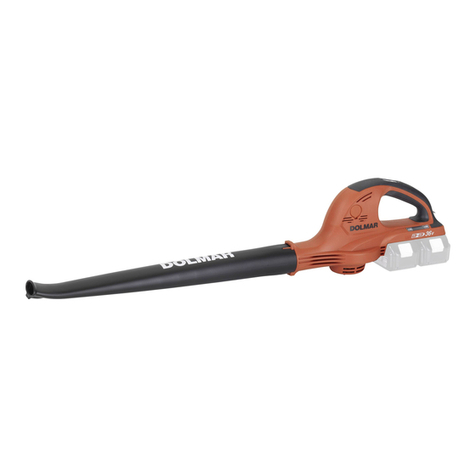
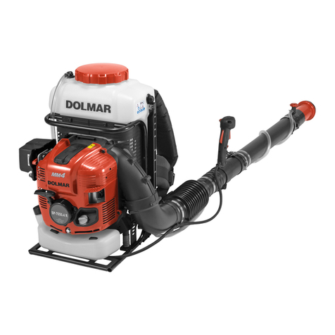
Dolmar AG3751 User manual

AG3751
EN Cordless Blower INSTRUCTION MANUAL 7
FR
SOUFFLEUR SANS FIL (ASPIRO /
SOUFFLEUR (SANS FIL))
MANUEL D’INSTRUCTIONS 15
DE Gebläse (Sauger) BETRIEBSANLEITUNG 24
IT ISTRUZIONI PER L’USO 33
NL Accubladblazer GEBRUIKSAANWIJZING 42
ES MANUAL DE
INSTRUCCIONES 51
PT
MANUAL DE INSTRUÇÕES 60
DA Akku blæser BRUGSANVISNING 69
EL 77
TR KULLANMA KILAVUZU 87

1
2
1
1
2
1 2
1
2
3
2

2
1
3
1
1
1
1 2
33
1
2 3
1
2
3
3

1
2
2
3
1
1
2
1
1
1
1
2
3
4

1
2
21
3
1
1
1
1
4
3
2
5

1
6

7ENGLISH
SPECIFICATIONS
Model: AG3751
Capacities Air volume 0 - 13.4 m3/min
Air speed (average) 0 - 54 m/s
Air speed (max.) 0 - 65 m/s
Dimensions (L x W x H) *1 341 mm x 193 mm x 415 mm
Rated voltage D.C. 36 V
Net weight Blower *2 3.8 - 5.2 kg
Vacuum *3 6.0 - 6.6 kg
*1. Without pipes, nozzles, dust bag, shoulder strap, and battery cartridges.
shoulder strap.
*3. With suction pipe, suction nozzle, elbow pipe, dust bag and shoulder strap, and without blower pipe, end nozzle
without notice.
-
est combination, according to EPTA-Procedure 01/2014, are shown in the table.
BL1815N / BL1820 / BL1820B / BL1830 / BL1830B / BL1840 / BL1840B / BL1850 / BL1850B / BL1860B
• Some of the battery cartridges listed above may not be available depending on your region of residence.
WARNING: Use of any other battery cartridges may cause
The followings show the symbols used for the equip-
ment. Be sure that you understand their meaning before
use.
Take particular care and attention.
Read instruction manual.
Keep hands away from rotating parts.
Long hair may cause entanglement
accident.
Keep bystanders away.
Wear eye and ear protection.
Do not expose to moisture.
Ni-MH
Li-ion Only for EU countries
Do not dispose of electric equipment or
battery pack together with household waste
material!
In observance of the European Directives,
on Waste Electric and Electronic
Equipment and Batteries andAccumulators
and Waste Batteries andAccumulators
and their implementation in accordance
with national laws, electric equipment and
batteries and battery pack(s) that have
reached the end of their life must be col-
lected separately and returned to an envi-
ronmentally compatible recycling facility.
The machine is intended for blowing and vacuuming.
The typicalA-weighted noise level determined accord-
ing to EN50636-2-100:
Sound pressure level (LpA) : 84.8 dB(A)
Uncertainty (K) : 1.3 dB(A)
Sound power level (LWA) : 94.9 dB (A)
Uncertainty (K) : 0.3 dB(A)

8ENGLISH
NOTE: The declared noise emission value(s) has
been measured in accordance with a standard test
method and may be used for comparing one tool with
another.
NOTE: The declared noise emission value(s)
may also be used in a preliminary assessment of
exposure.
WARNING:
WARNING:
WARNING: -
The vibration total value (tri-axial vector sum) deter-
mined according to EN50636-2-100:
Work mode: operation without load (blowing)
Vibration emission (ah) : 2.5 m/s2or less
Uncertainty (K) : 1.5 m/s2
Work mode: operation without load (vacuuming)
Vibration emission (ah) : 2.5 m/s2or less
Uncertainty (K) : 1.5 m/s2
NOTE: The declared vibration total value(s) has been
measured in accordance with a standard test method
and may be used for comparing one tool with another.
NOTE: The declared vibration total value(s) may also
be used in a preliminary assessment of exposure.
WARNING:
WARNING: -
For European countries only
The EC declaration of conformity is included asAnnex A
to this instruction manual.
SAFETY WARNINGS
WARNING:
Failure to follow the warnings and
-
1.
2.
3. -
4.
1.
2.
3.
-
-
4.
5.
Non-skid,
closed-toed safety boots and shoes will reduce the

9ENGLISH
6.
Protective equipment such
as a dust mask, non-skid safety shoes, hard hat or
hearing protection used for appropriate conditions
1.
•
•
•
•
•
2.
3.
4.
5.
6.
7.
8. -
9.
10.
11.
•
-
•
•
12.
13.
14.
15.
16.
17.
-
18.
19.
20.
1.
2.
3.
4.
5.
6.
7.
1.
Acharger that is suitable for
when used with another battery pack.
2. -
Use of any other battery
3.
Shorting the battery termi-
4.
-
irritation or burns.
5. -
may exhibit unpredictable behaviour resulting in
6.
-
perature above 130 °C may cause explosion.
7.
-
Charging improperly or at temperatures

10 ENGLISH
1.
The cell may explode. Check with local codes for
possible special disposal instructions.
2.
Released
electrolyte is corrosive and may cause damage to the
eyes or skin. It may be toxic if swallowed.
3.
4.
5.
1.
This will ensure that the safety of the power
tool is maintained.
2. Service
of battery packs should only be performed by the
manufacturer or authorized service providers.
WARNING:
1. -
2.
3.
4.
-
5.
(1) -
(2) -
(3)
6.
7.
8.
9.
10.
-
For commercial transports e.g. by third parties,
forwarding agents, special requirement on pack-
aging and labeling must be observed.
For preparation of the item being shipped, consult-
ing an expert for hazardous material is required.
Please also observe possibly more detailed
national regulations.
battery in such a manner that it cannot move
around in the packaging.
11.
12.
Installing the batteries to
-
sive heat, explosion, or leak of electrolyte.
13.
CAUTION:
Use of non-genuine Makita batteries, or batteries that
have been altered, may result in the battery bursting
also void the Makita warranty for the Makita tool and
charger.
1.
2. -
3. -
4.
ASSEMBLY
CAUTION:
NOTICE:
Otherwise,
the machine does not work.

11 ENGLISH
and nozzle
Attach the blower pipe to the main unit.
Insert the blower pipe into the main unit with the bolt
using the hex wrench.
Bolt Blower pipe
Align the protrusion on the blower pipe with the
groove on the end nozzle, then attach the end nozzle to
the blower pipe, and then turn the end nozzle to lock it
into place.
End nozzle Blower pipe
To remove the blower pipe and end nozzle, perform the
installation procedure in reverse.
NOTE: The length of the nozzle can be changed by
End nozzle Blower pipe
Optional accessory
nozzle, and then turn it to lock it into place.
Flat nozzle Extension nozzle End
nozzle
to the blower pipe.
Flat nozzle Extension nozzle Blower
pipe
the installation procedure in reverse.
CAUTION:
If the
CAUTION:
Using other shoulder
Attach the hooks of the shoulder strap to the machine
Hook
The shoulder strap features a means of quick release.
Simply squeeze the sides of the buckle to release the
machine from the shoulder strap.
Buckle
and nozzle
Optional accessory
Align the triangle mark on the suction nozzle with
that on the suction pipe, and then insert the suction
nozzle into the suction pipe until the latch on the nozzle
snaps into place.
Suction nozzle Suction pipe Triangle
mark
Loosen the bolt on the fan cover using the hex
wrench, and open the fan cover.
Bolt Fan cover Hex wrench
Align the triangle mark on the suction pipe
with mark on the main unit, and then attach the
suction pipe to the main unit.
Suction pipe Triangle mark mark
Turn the suction pipe clockwise so that the bolt
on the pipe is aligned with the hole on the main unit,
secure the pipe to the main unit.
Suction pipe Bolt
To remove the suction pipe and nozzle, perform the
installation procedure in reverse.
Optional accessory
Insert the elbow pipe into the dust bag and tighten
Dust bag Elbow pipe Belt
Attach the elbow pipe to the main unit.
Insert the elbow pipe into the main unit with the bolt
using the hex wrench.
Bolt Elbow pipe
Attach the hook of the dust bag to the shoulder
strap, and then attach the hooks of the shoulder strap to
Hook
To remove the dust bag and elbow pipe, perform the
installation procedure in reverse.

12 ENGLISH
FUNCTIONALDESCRIPTION
CAUTION:
CAUTION:
CAUTION:
-
CAUTION:
If not,
it may accidentally fall out of the machine, causing
CAUTION:
If the cartridge does not slide in easily, it is
not being inserted correctly.
Red indicator Button Battery cartridge
To remove the battery cartridge, slide it from the machine
while sliding the button on the front of the cartridge.
To install the battery cartridge, align the tongue on the
battery cartridge with the groove in the housing and slip
it into place. Insert it all the way until it locks in place
with a little click. If you can see the red indicator on the
upper side of the button, it is not locked completely.
Only for battery cartridges with the indicator
Indicator lamps Check button
Press the check button on the battery cartridge to indi-
cate the remaining battery capacity. The indicator lamps
light up for a few seconds.
75% to 100%
50% to 75%
25% to 50%
0% to 25%
Charge the
battery.
The battery
may have
malfunctioned.
NOTE: Depending on the conditions of use and the
from the actual capacity.
The machine is equipped with a machine/battery
power to the motor to extend machine and battery life.
The machine will automatically stop during operation if
the machine or battery is placed under one of the fol-
lowing conditions:
When the machine or battery is operated in a manner
that causes it to draw an abnormally high current, the
machine automatically stops and the lamp for mode
1 blinks in green. In this situation, turn the machine
to become overloaded. Then turn the machine on to
restart.
When the machine or battery is overheated, the
machine stops automatically and the lamp for mode 1
lights up in red. In this case, let the machine and battery
cool down before turning the machine on again.
When the battery capacity is not enough, the machine
stops automatically and the lamp for mode 1 blinks in
red. In this case, remove the battery from the machine
and charge the battery.
WARNING:
To turn on the machine, press the main power switch.
The lamps for mode 1 and mode 2 light up in green. To
(1) Lamp for mode 1 (2) Lamp for mode 2
(3) Main power switch
You can use the machine in the vacuuming mode. In the
vacuuming mode, the suction volume becomes smaller
than in the normal mode.
When you turn on the machine, the machine starts up in
the normal mode. To use the machine in the vacuuming
mode, press the main power switch when the machine
lamp for mode 1 lights up in green. When you press the
main power switch again, the machine returns to the
normal mode, and the lamps for mode 1 and mode 2
light up in green.

13 ENGLISH
NOTE: The lamp for mode 1 blinks in green if the
machine is operated under unoperatable conditions.
The lamp blinks in one of the following conditions.
• The switch trigger is pulled, when the bolt on the
or the bolt on the blower pipe or elbow pipe is
• The machine is turned on, when the control
while you are pulling the switch trigger.
NOTE:
function. To avoid unintentional start up, the main
power switch will automatically shut down when the
switch trigger is not pulled for a certain period after
the main power switch is turned on.
WARNING: -
Switch trigger
To start the machine, simply pull the switch trigger. The
speed is increased by increasing pressure on the switch
trigger. Release the switch trigger to stop.
The cruise control function allows the operator to main-
tain a constant speed without pulling the trigger. To
increase the speed, turn the control lever forward. To
decrease the speed, turn the control lever backward.
Control lever
When not in use, store the hex wrench as illustrated to
keep it from being lost.
Hex wrench
If you turn on the machine while pulling the switch trig-
release the switch trigger and return the control lever
fully, and then turn on the machine.
The machine is equipped with the electronic function for
easy operation.
• Constant speed control
The speed control function provides the constant
rotation speed regardless of load conditions.
OPERATION
CAUTION:
Sand or dust may
enter from suction inlet and cause a malfunction or
CAUTION:
blowing operation by moving it around slowly. When
blowing around building, big stone or vehicle, direct the
nozzle away from them. When performing an operation
in a corner, start from the corner and then move to wide
area.
CAUTION:
CAUTION:
CAUTION:
CAUTION:
NOTICE:
Otherwise, a malfunction
may occur.
NOTICE:
Otherwise, a malfunction may occur.
NOTICE: -
Put the shoulder strap and dust bag on the shoul-
strap.
Shoulder strap Carry handle Assist
handle Dust bag
Hold the carry handle with your right hand and the
assist handle with the other hand.
trigger so that the suction force is appropriate for the
work location and conditions.

14 ENGLISH
MAINTENANCE
CAUTION:
To maintain product SAFETY and RELIABILITY, repairs,
-
formed by Makita/DolmarAuthorized or Factory Service
Centers, always using Makita/Dolmar replacement parts.
one dipped in soapy water and wrung out.
NOTICE:
Remove dust or dirt from the suction inlets.
Suction inlet
TROUBLESHOOTING
do not attempt to disassemble the machine. Instead, ask Makita/DolmarAuthorized Service Centers, always using
Makita/Dolmar replacement parts for repairs.
Motor does not run. Battery cartridge is not installed. Install the battery cartridge.
Battery problem (under voltage)
replace battery.
For blower
The blower pipe is not attached.
The fan cover is not closed.
Attach the blower pipe, and then tighten the bolt.
Close the fan cover, and then tighten the bolt.
The elbow pipe or suction pipe is not
attached.
Attach the elbow pipe or suction pipe, and then
tighten the bolt.
The drive system does not work
correctly. Ask your local authorized service center for repair.
Motor stops running after a little use. Battery's charge level is low.
replace battery.
Overheating. Stop using the machine to allow it to cool down.
The machine does not reach the
maximum speed. Battery is installed improperly. Install the battery cartridge as described in this
manual.
Battery power is dropping.
replace battery.
The drive system does not work
correctly. Ask your local authorized service center for repair.
Abnormal vibration:
stop the machine immediately! The drive system does not work
correctly. Ask your local authorized service center for repair.
Motor cannot stop:
Remove the battery immediately! Electric or electronic malfunction. Remove the battery and ask your local authorized
service center for repair.
OPTIONALACCESSORIES
CAUTION:
The use
of any other accessories or attachments might pres-
attachment for its stated purpose.
If you need any assistance for more details regard-
ing these accessories, ask your local Makita/Dolmar
Service Center.
• Vacuum kit
• Extension nozzle
• Flat nozzle
• Shoulder strap
• Makita/Dolmar genuine battery and charger
NOTE: Some items in the list may be included in the
product package as standard accessories. They may

15 FRANÇAIS
SPÉCIFICATIONS
Modèle : AG3751
Capacités Volume d’air 0 - 13,4 m3/min
Vitesse de l’air (moyenne) 0 - 54 m/s
Vitesse de l’air (max.) 0 - 65 m/s
Dimensions (L x Px H)*1 341 mm x 193 mm x 415 mm
Tension nominale 36 VCC
Poids net 3,8 - 5,2 kg
Aspirateur*3 6,0 - 6,6 kg
*1. Sans tuyaux, buses, sac à poussière, bandoulière et batteries.
-
sière et bandoulière.
-
trémité et buse plate.
plus lourde, conformément à la procédure EPTA01/2014, sont indiquées dans le tableau.
BL1815N / BL1820 / BL1820B / BL1830 / BL1830B / BL1840 / BL1840B / BL1850 / BL1850B / BL1860B
• Certaines batteries répertoriées ci-dessus peuvent ne pas être disponibles selon la région où vous résidez.
AVERTISSEMENT : L’utilisation de n’importe quelle
autre batterie peut provoquer des blessures et/ou un incendie.
Vous trouverez ci-dessous les symboles utilisés pour
toute utilisation.
Veuillez être prudent et rester attentif.
Lire le mode d’emploi.
Gardez vos mains à l’écart des pièces en
rotation.
Les cheveux longs risquent de se prendre
dans les pièces en mouvement.
Tenez les personnes à l’écart.
Porter des lunettes de protection et un
serre-tête antibruit.
Ne pas exposer à l’humidité.
Ni-MH
Li-ion Pour les pays de l’Union européenne
uniquement
les batteries avec vos ordures ménagères !
Conformément aux directives européennes
relatives aux déchets d’équipements
électriques et électroniques et aux piles
et accumulateurs ainsi qu’aux déchets de
piles et d’accumulateurs et leur mise en
œuvre conformément aux lois nationales,
les équipements électriques, les piles et les
une usine de recyclage respectueuse de
l’environnement.
Niveau de bruit pondéréA typique, déterminé selon
EN50636-2-100 :
Niveau de pression sonore (LpA) : 84,8 dB (A)
Incertitude (K) : 1,3 dB (A)
Niveau de puissance sonore (LWA ) : 94,9 dB (A)
Incertitude (K) : 0,3 dB (A)

16 FRANÇAIS
NOTE : La ou les valeurs d’émission de bruit décla-
rées ont été mesurées conformément à la méthode
de test standard et peuvent être utilisées pour com-
parer les outils entre eux.
NOTE : La ou les valeurs d’émission de bruit décla-
rées peuvent aussi être utilisées pour l’évaluation
préliminaire de l’exposition.
AVERTISSEMENT :
AVERTISSEMENT :
AVERTISSEMENT :
Valeur totale de vibrations (somme de vecteur triaxial)
déterminée selon EN50636-2-100 :
Émission de vibrations (ah) : 2,5 m/s2ou moins
Incertitude (K) : 1,5 m/s2
Mode de travail : fonctionnement à vide (aspiration)
Émission de vibrations (ah) : 2,5 m/s2ou moins
Incertitude (K) : 1,5 m/s2
NOTE : La ou les valeurs de vibration totales décla-
rées ont été mesurées conformément à la méthode
de test standard et peuvent être utilisées pour com-
parer les outils entre eux.
NOTE : La ou les valeurs de vibration totales décla-
rées peuvent aussi être utilisées pour l’évaluation
préliminaire de l’exposition.
AVERTISSEMENT :
AVERTISSEMENT :
Pour les pays européens uniquement
La déclaration de conformité CE est fournie enAnnexe
Aà ce mode d’emploi.
CONSIGNES DE SÉCURITÉ
AVERTISSEMENT :
Il
y a risque d’électrocution, d’incendie et/ou de graves
blessures si les mises en garde et les instructions ne
sont pas respectées.
-
1.
2. -
3.
-
4. -
1.
2.
3.
-

17 FRANÇAIS
4.
5.
Porter des bottes ou des chaussures
de sécurité fermées et antidérapantes permet de
réduire le risque de blessure.
6. -
-
Les équipements de sécurité tels que les
masques contre les poussières, les chaussures
de sécurité antidérapantes, les casques ou les
protecteurs d’oreilles utilisés pour les conditions
appropriées réduiront les blessures.
1. -
•
•
• -
•
•
2.
3.
4.
5.
6.
7.
8. -
9.
10.
11.
•
•
•
12.
13. -
14.
15.
-
16.
17.
18.
19. -
20.
1.
2.
3.
4. -
-
5.
6.
7. -

18 FRANÇAIS
1. -
Un chargeur qui
présenter un risque d’incendie s’il est utilisé avec
un autre type de batterie.
2.
L’utilisation
de toute autre batterie peut présenter un risque de
blessure et d’incendie.
3.
-
Court-circuiter les bornes d’une batterie
entre elles peut provoquer des brûlures ou un
incendie.
4.
Le
liquide s’échappant de la batterie peut provoquer
une irritation ou des brûlures.
5.
Une batterie endom-
imprévisible susceptible d’entraîner un incendie,
une explosion ou des blessures.
6.
L’exposition au feu
ou à une température supérieure à 130 °C peut
provoquer une explosion.
7.
Une charge incorrecte ou à une
température en dehors de la plage indiquée peut
endommager la batterie et augmenter le risque
d’incendie.
1.
L’élément de la pile pourrait exploser. Consultez
les codes locaux pour de possibles instructions de
mise au rebut spéciales.
2.
L’électrolyte qui s’échappe de la batterie est cor-
rosif et peut irriter la peau ou les yeux. Il peut être
toxique en cas d’ingestion.
3.
4.
5.
1.
La sécurité de l’outil élec-
trique sera ainsi préservée.
2.
-
quement par le fabricant ou un dépanneur agréé.
CONSERVEZ CES
AVERTISSEMENT :
-
-
1.
2.
3.
4.
5.
(1) -
(2)
-
(3)
-
6.
7.
8.
9.
10.
Lors du transport commercial par des tierces
parties ou des transitaires par exemple, des exi-
d’emballage doivent être respectées.

19 FRANÇAIS
Pour la préparation de l’article expédié, il est
nécessaire de consulter un expert en matériau
dangereux. Veuillez également respecter les
réglementations nationales susceptibles d’être
plus détaillées.
Recouvrez les contacts exposés avec du ruban
adhésif ou du ruban de masquage et emballez la
batterie de telle sorte qu’elle ne puisse pas bouger
dans l’emballage.
11. -
12.
L’insertion de
batteries dans des produits non conformes peut
provoquer un incendie, une chaleur excessive,
une explosion ou une fuite de l’électrolyte.
13.
CONSERVEZ CES
ATTENTION :
L’utilisation de batteries de marque
-
voquer l’explosion des batteries, ce qui présente un
risque d’incendie, de dommages matériels et corpo-
rels. Cela annulera également la garantie Makita pour
l’outil et le chargeur Makita.
1. -
2. -
3.
4. -
ASSEMBLAGE
ATTENTION :
REMARQUE :
Autrement, la machine ne fonctionnera pas.
le boulon tourné vers la gauche comme illustré sur la
l’unité principale, puis serrez fermement le boulon au
moyen de la clé hexagonale.
Boulon
-
nez la buse d’extrémité pour qu’elle se verrouille en
place.
Buse d’extrémité
NOTE :
Buse d’extrémité
de la rallonge de buse
Accessoire en option
Fixez la buse plate ou la rallonge de buse sur la buse
d’extrémité, puis tournez-la pour qu’elle se verrouille
en place.
Buse plate Rallonge de buse Tuyau
adaptateur
-
Buse plate Rallonge de buse Tube
-
tuez la procédure de pose en sens inverse.
ATTENTION :
Si les
de provoquer des blessures.
ATTENTION :
L’utilisation
d’une autre bandoulière peut entraîner des blessures.
Fixez les crochets de la bandoulière sur la machine
Crochet
La bandoulière est pourvue d’un système de desser-
pour que la machine se décroche de la bandoulière.
Boucle

20 FRANÇAIS
Accessoire en option
Alignez le repère triangulaire sur le suceur avec
celui sur le tube d’aspiration, puis insérez le suceur
suceur se verrouille en place.
Suceur Tube d’aspiration Repère
triangulaire
Desserrez le boulon sur le couvercle du ventila-
teur au moyen de la clé hexagonale et ouvrez le cou-
vercle du ventilateur.
Boulon Couvercle du ventilateur Clé
hexagonale
Alignez le repère triangulaire sur le tube d’aspira-
tion avec le repère
tube d’aspiration sur l’unité principale.
Tube d’aspiration Triangle repère
Tournez le tube d’aspiration dans le sens des
aiguilles d’une montre de sorte que le boulon sur le tube
soit aligné avec le trou sur l’unité principale, puis serrez
fermement le boulon au moyen de la clé hexagonale
Tube d’aspiration Boulon
procédure de pose en sens inverse.
Accessoire en option
Insérez le tube coudé dans le sac à poussière et
Sac à poussière Tube coudé Sangle
Fixez le tube coudé à l’unité principale.
Insérez le tube coudé dans l’unité principale avec le
boulon tourné vers la gauche comme illustré sur la
l’unité principale, puis serrez fermement le boulon au
moyen de la clé hexagonale.
Boulon Tube coudé
Fixez le crochet du sac à poussière à la bandou-
Crochet
-
tuez la procédure de pose en sens inverse.
DESCRIPTION DU
FONCTIONNEMENT
ATTENTION :
ATTENTION :
ATTENTION :
Si vous ne tenez pas fermement la machine et la batterie, elles
peuvent vous glisser des mains, et s’abîmer ou vous blesser.
ATTENTION :
Sinon, elle risque de tomber accidentel-
lement de la machine, ce qui peut blesser l’opérateur
ou une autre personne qui se trouve à proximité.
ATTENTION :
Si elle ne glisse pas facilement, c’est que vous
ne l’insérez pas correctement.
Voyant rouge Bouton Batterie
Pour retirer la batterie, faites-la glisser hors de la machine
tout en faisant glisser le bouton à l’avant de la batterie.
Pour mettre en place la batterie, alignez la languette sur la
batterie avec la rainure sur le compartiment et insérez-la.
entendre. Si le voyant rouge sur le dessus du bouton est
Uniquement pour les batteries avec voyant lumineux
Témoins
pour indiquer la charge restante de la batterie. Les
témoins s’allument pendant quelques secondes.
75 % à 100 %
50 % à 75 %
25 % à 50 %
0 % à 25 %
Chargez la
batterie.
Anomalie
possible
de la batterie.
Table of contents
Languages:
Other Dolmar Blower manuals

Dolmar
Dolmar PB-7660.4 User guide

Dolmar
Dolmar SP-7650.4 R User manual

Dolmar
Dolmar PB-7601.4 User manual

Dolmar
Dolmar AG-3729 User manual

Dolmar
Dolmar AG-3628 User manual

Dolmar
Dolmar PB-252.4 User manual

Dolmar
Dolmar PB-250 User manual

Dolmar
Dolmar PB-252.4 User manual

Dolmar
Dolmar PB-252.4 User manual

Dolmar
Dolmar SP-7650.4 R User guide

Dolmar
Dolmar AG-3729 User manual

Dolmar
Dolmar SP-7650.4 R User guide

Dolmar
Dolmar EB166 User guide

Dolmar
Dolmar PB-251.4 User manual

Dolmar
Dolmar AG-3750 User manual

Dolmar
Dolmar PB-500 R User manual

Dolmar
Dolmar PB-251.4 Guide

Dolmar
Dolmar PBV250 User guide

Dolmar
Dolmar PB-7600.4 User manual

Dolmar
Dolmar MG5300 User guide