manuals.online logo
Brands
  1. Home
  2. •
  3. Brands
  4. •
  5. Dometic
  6. •
  7. Accessories
  8. •
  9. Dometic A&E Systems 8500 Guide

Dometic A&E Systems 8500 Guide

1
B. REMOVAL OF THE AWNING FROM THE COACH
FIG. 1
1/2" TEK
SCREW
AWNING
RAIL
REMOVE FROM
BOTH SIDES
FABRIC
SECTION TOP
BRACKET
Screwdriver
Electric Drill
Step Ladder
3/16" Pop
RivetsPopRivet
Vise Grips®
Socket Wrench Set
3/16" Drill Bit
1/8" Pop Rivets
EndCapGuide
Tools Required:
Fabric Roller Tube
For Models 8500 & 9000
Torsion Assembly
REPLACEMENT INSTRUCTIONS FOR AWNING
The Fabric Roller Tube Assembly (FRTA) consists of a fabric,
a roller tube and torsion assemblies.
Use extreme care. Springs under tension are
dangerous. If not controlled they will unwind
quickly. Keep hands and clothing clear of top
casting, as personal injury may result.
A. GENERAL INSTRUCTIONS
4. Remove both of the patio feet from their mounting
brackets and extend the adjustable arms until each patio
foot rests on the ground and lock button locks in a hole.
5. Slide the awning fabric or roller cover out of the awning
rail.
a. To keep the awnings from unwinding during this
step, be sure the cam lock lever is in the roll down
position. A 1/8" cotter pin can be inserted in each
torsion assembly for positive locking of the roller
tube. See FIG. 2.
NOTE: Awning removal from the coach is NOT necessary
when replacing a torsion assembly. Proceed to Section
C, Steps 1 & 2, Sections D, Steps 1-3, and Section L,
Steps 1-3.
1. In all instances of fabric or roller tube replacement, it will
be necessary to have a large work area to allow
complete unrolling of the awning. This work area must
be clean and smooth so the fabric will not be damaged.
2. Remove the TEK screws securing the awning fabric or
roller cover at each end of the awning fabric. See FIG. 1.
3. Remove both top mounting brackets on the ends of the
awning rail. See FIG. 1
REVISION
Form No. 3107299.054 3/02
(Replaces 3107299.046)
(French 3109898.027)
©2002 Dometic Corporation
LaGrange, IN 46761
These instructions must be read and under-
stood before installation, adjustment, service
or maintenance is performed. This unit must
be installed by a qualified serviceman. Modi-
fication of this product can be extremely haz-
ardous and could result in personal injury or
property damage.
TOP CASTING
COTTER
PIN
MOVE LEVER POSITION TO
ROLL DOWN POSITION RIGHT-HAND SIDE
(VIEWED FROM FRONT)
FIG. 2
Tool
Adjustable Wrench
1/8" Drill Bit
SmallFile
2
C. UNWINDING A TORSION ASSEMBLY SPRING
NOTE: If the awning is installed on a coach, complete the
following steps on a step ladder, with the awning fabric
unrolled two feet from the awning rail. The unwinding can also
be done while standing on the ground and the awning fully
extended and the opposite side rafter locked in place. The
torsion spring will be wound with 8/eight more turns in this
position and is extremely dangerous.
Severe injuries can result from the rapid spin-off of
the top casting. Use Vise Grips®- NEVER use bare
hands - to handle a top casting under spring ten-
sion.
1. Clamp a Vise Grip® tightly on the top casting, or insert
the crank (3107905.006) into top casting. Remove the 1/
4-20 hex head machine screw from the top casting. See
FIG. 3 and FIG. 3A.
2. Take the top casting carefully out of the main support
arm (see NOTE below). Slowly let the torsion spring
unwind completely. Repeat Steps 1 & 2 for the opposite
end.
NOTE: If the awning's right-hand torsion assembly has been
pinned, the cotter pin must be removed from the torsion
assembly before the spring can be unwound. The cam lock
lever on the right-hand torsion assembly must be turned
clockwise to the roll up position, before the spring can be
unwound.
1. Make sure the torsion spring has been relieved of its
tension (see Section C.)
2. Mark or make note of the location of the fabric and the
end cap on the roller tube. This is necessary to reposition
the new torsion, fabric or roller tube exactly the same
when the new part is installed.
NOTE: Some roller tubes have notches and the end cap
has tabs, that will allow the torsion to fit only in one
position. The fabric must be positioned exactly as shown
in FIG. 5 or the lock lever will not be positioned correctly
when installed on the coach.
3. Drill out the two rivets using a 3/16" drill bit. Remove
torsion assembly and rivet bodies from roller tube. See
FIG. 4.
D. HOW TO REMOVE A TORSION ASSEMBLY
LOCK
LEVER
TOP
CASTING
MAIN SUPPORT
ARM ASSEMBLY
VISE-
GRIPS®
1/4-20 X 1/2" HEX
HD. MACH. SET SCREW
FIG. 3
FIG. 4
FIG. 3A
LOCK
LEVER
TOP
CASTING
1/4-20 X 1/2" HEX
HD. MACH. SET SCREW
MAIN SUPPORT
ARM ASSEMBLY
CRANK
3107905.006
3
E. HOW TO REMOVE FABRIC FROM ROLLER TUBE / COVER
1. Remove both torsions. See Section D, Steps 1-3 for
torsion removal.
2. Roll the awning completely out on a clean smooth
surface.
3. With the awning laying flat, slide the roller tube out from
fabric.
4. The metal roller cover on 8500 and 9000 models are
F. INSTALLING FABRIC ON ROLLER TUBE
1. Unfold the new fabric and lay it on top of the existing
fabric in the exact same position. Be sure the new
fabric is the correct size and color. If roller tube is being
replaced, make sure it is the correct length and position
it with the notch located as shown in FIG. 5.
2. Dometic requires the use of the end cap guide to prevent
damages to the fabric, when replacing the fabric/roller
tube. Place the end cap guide supplied with the replace-
ment fabric/roller tube on the end of the roller tube. Slide
the fabric and valance ropes through the end cap guide
and onto the roller tube. See figure 5.
NOTE: When changing the fabric, it is vital that the same
groove(s) be used. This eliminates the need to redrill any
holes (i.e. center support).
3. Guide the roller tube over the poly-rope(s) of the fabric.
Be careful not to damage the roller tube or the fabric.
crimped to the poly ropes. Use needle nose pliers and
flat blade screw dirver to spread open the channel before
removing fabric.
NOTE: Some 9000 model awning,secured the fabric to the
roller cover with 1/8" pop rivets. It is necessary to remove
the 1/8" pop rivets from both ends of the roller cover.
Once the rivets are removed, you can slide the fabric out
of the cover. See FIG. 6 & 7.
FIG. 5
ROLLER
TUBE
SLIDE FABRIC AND
VALANCE ROPES
THROUGHGUIDE
4. Center the fabric on the roller tube and hand-roll the entire
assembly in the same direction as the original fabric.
NOTCH
VALANCE
ROPE
OPEN
GROOVE
FABRIC
GROOVE PLACE END
CAP GUIDE
ON ROLLER
TUBE
4
Installing a new replacement fabric on 9000 Model
awning roller cover with 6 slats. See FIG. 7.
1. Follow steps 2-8 in Section G.
H. FABRIC REPLACEMENT ON 9000 WITH 6 SLAT ROLLER COVER
G. FABRIC REPLACEMENT ON 9000 WITH 7 SLAT ROLLER COVER
Installing a new replacement fabric on a Model 9000
roller cover with 7 slats and a vinyl strip. See FIG. 6:
1. Remove vinyl strip A(FIG. 11), and hinge slat B(FIG. 10)
from top slat C(FIG. 8). Remove two of Slat D (Fig. 9).
Discard vinyl strip A, hinge slat B and the two Dslats .
2. Remove top slat C(FIG. 8) from roller cover assembly
and keep to be installed later.
Note: 9000 awning with 6 slats requires removal of one
slat D. (8500 and 9000 with 5 slats will require one slat
D to be remove and discarded if a new roller cover is being
replaced.)
3. The new replacement fabric will be installed as shown in
FIG. 7.
4. Use a small file to round the ends of the groove in the
5/16" channel of the main slat D(FIG. 9).
5. Slide the 5/16" channel of the main slat D onto the poly-
Installing a new replacement fabric on 8500 and 9000
model awning roller cover with 5 slats. Use Section G.
1. Follow steps 2-8 in Section G.
I. FABRIC REPLACEMENT ON 8500 AND 9000 WITH 5 SLAT ROLLER COVER
rope located approximately 12" from the top edge of the
fabric.
6. Install two pop rivets in the main slat Don both ends to
prevent the fabric from shifting in roller cover. If a new
roller cover assembly is being installed, a 1/8" hole will
need to be drilled 1-1/2" to 2" from end of the main slat
for the pop rivets. To prevent damage, be sure to remove
any burrs left by the drill.
NOTE: On 8500 models crimp the channel with pliers to
hold fabric.
7. Use a small file to round the ends of the 5/16" grooves on
the top slat C(FIG. 8) to prevent tearing of the fabric.
Slide the top slat Conto both the 1/4" channel of the fifth
main slat Dand the poly-rope 1-1/2" from the edge of the
fabric.
8. Install the screws into the edge of the roller cover
assembly. See FIG. 7.
Installing new roller cover on model 9000 with 6 slats.
See FIG. 7.
1. Follow steps 1-8 in Section G.
J. INSTALLING NEW ROLLER COVER WITH 6 SLATS
K. INSTALLING NEW ROLLER COVER WITH 5 SLATS
Installing new roller cover on 8500 model with 5 slats .
See FIG. 7.
1. Follow steps 1-8 in Section G.
5
1/4" CHANNEL
TOP SLAT "C"
VIEW RH END
MAIN SLAT "D"
VIEW RH END
HINGE SLAT "B"
INSTALL A 1/8"
POP RIVET
EACH END
D
D
D
D
D
C
INSTALL A 1/8"
POP RIVET
EACH END
D
D
D
D
D
C
VINYL STRIP "A"
E
HINGE SLAT "B"
FIG. 6
FIG. 7
E
5/16" CHANNEL
INSTALL TOWARD
CANOPY
FIG. 10
FIG. 9
FIG. 8
FIG. 11
VINYL STRIP "A"
FOR FIGS. 6–11
A - VINYL STRIP
B - HINGE SLAT
C - TOP SLAT
D - MAIN SLAT
E - AWNING RAIL
FIGURES 6 THROUGH 11
5/16" CHANNEL
BOTH ENDS
1/4" CHANNEL
INSTALL TOWARD
AWNING RAIL
5/16" ROD IN
AWNING RAIL
3/8" CHANNEL
FOR VINYL
STRIP "A"
Note: FIG. 6 shows 9000 model with 7 slats (1 "B" hinge slat, 1 "C" top slat and 5
"D" slats).
FIG. 7 shows 9000 Model with 6 slats (1 "C" and 5 "D" slats).
Drill out 1/8" pop
rivet, before
sliding out fabric
Drill out 1/8" pop
rivet, or spread
crimp before
sliding out fabric
Trim poly rope
even and crimp
end
Trim poly rope
even and crimp
end
6
NOTE: If the roller tube is new, the rivet holes are not drilled.
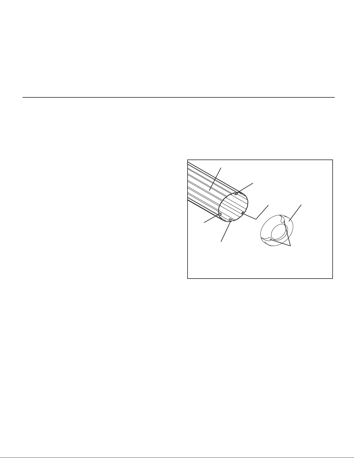
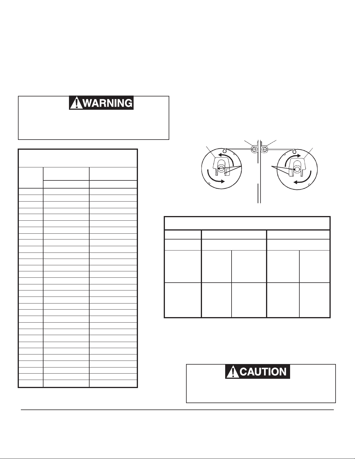
The torsion assemblies must be positioned as follows:
The left-hand torsion assembly position has the open
slot in the end cap aligned with the empty groove of the
roller tube.
Position the right-hand torsion assembly open hole
in the end cap in alignment with the empty groove in the
roller tube.If a new right-hand torsion assembly is being
installed and the roller tube does not have the notch
shown in FIG. 5. The two tabs inside the right-hand
torsion end cap must be broken off. See FIG. 13A.
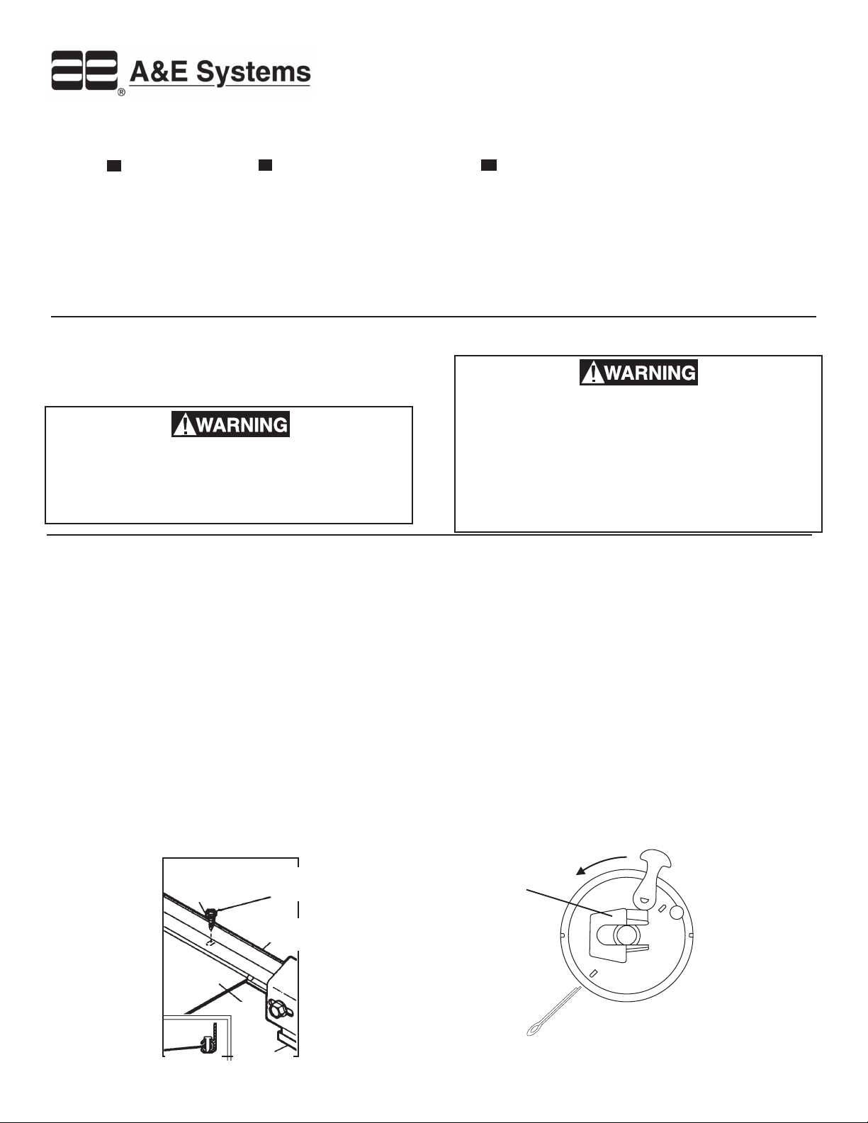
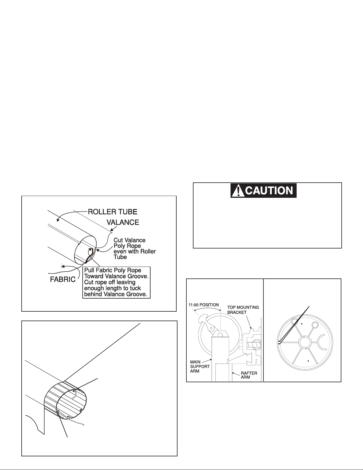
NOTE: Placing the end caps as suggested usually
positions the lock lever in the proper position when
awning is closed. The awning should be opened and
closed several times, and checked. The cam lock lever
should be at the "11:00" position . The end cap may have
to be removed and repositioned if it is not in the proper
location. See FIG. 13.
Models 8500 and 9000 19' - 25' have been manufac-
tured with both standard and heavy duty torsion
springs. Before reinstalling the torsion, properly
identify (Standard or Heavy Duty) the springs. This
is necessary for proper winding of the torsion. See
Spring Identification Chart on page 7.
4. Secure torsion assemblies to roller using 3/16" dia. x 3/8"
long stainless steel pop rivets.
1. To reduce the possibility of the poly rope interfering with
the cam lock mechanism, the right-hand torsion requires
the valance rope to be cut off even with the roller tube.
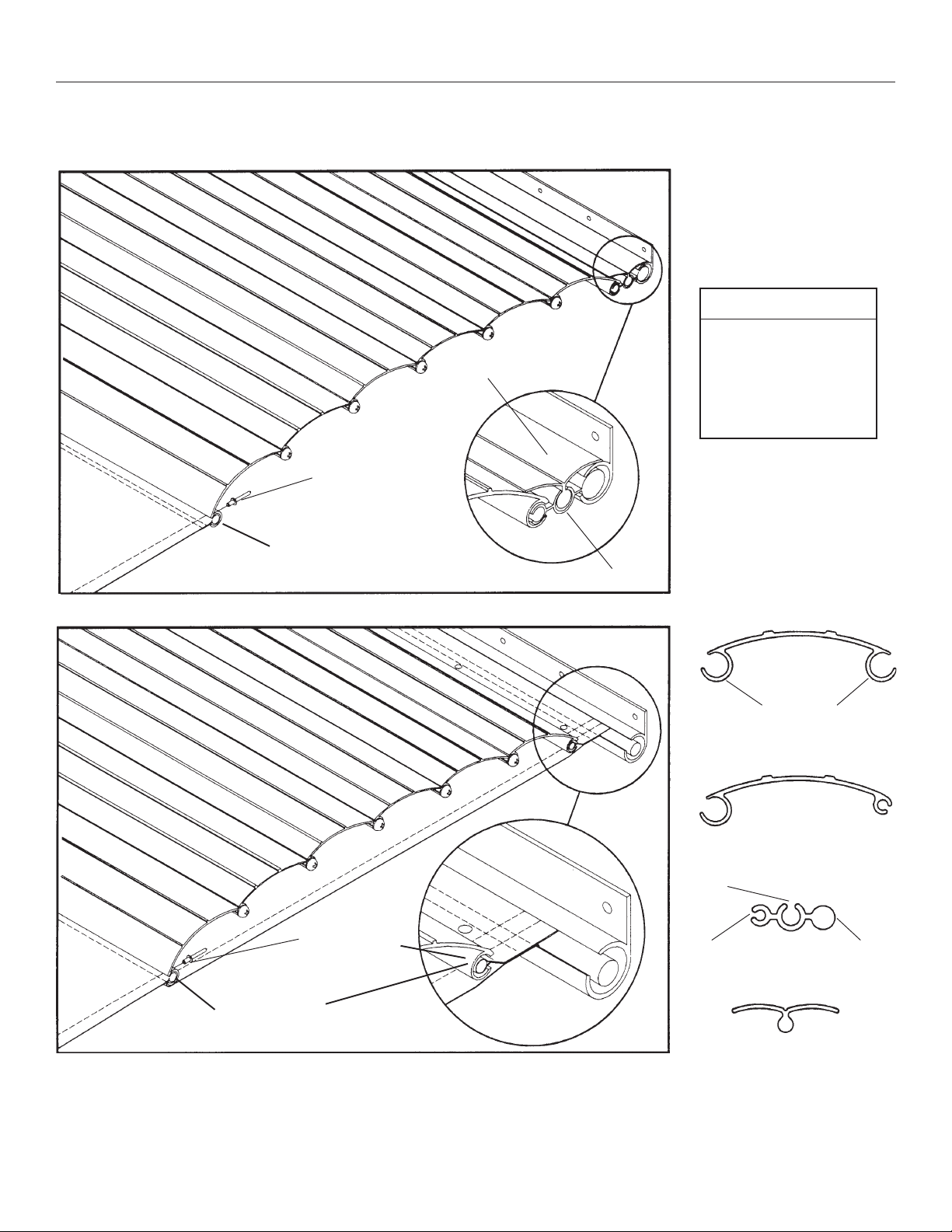
a. Steel Roller Tube: The poly rope on the fabric side
must be pulled toward the valance groove and cut
off – leaving enough length to tuck it behind the
valance groove. See FIG. 12.
b. Aluminum Roller Tubes: The poly rope on the
fabric side is cut 2" longer than the roller tube.
Stretch the poly rope and pull it toward the center
of the roller tube. Make sure it is locked in the
notch of the groove in the roller tube. See FIG.12A.
2. Reinstall the torsion assembly in the roller tube. Align
the rivet slots on the end cap with the holes in the roller
tube - in the exact same position as in Section D, Step
2. If a new roller tube is being used make sure the fabric
has been installed as directed in Section "F".
3. The poly ropes on the left-hand end of the roller tube
should be trimmed in the same as the right-hand. See
Section "L" Step 1.
L. REPLACING TORSION ASSEMBLIES
FIG. 12
FIG. 13
CUT VALANCE ROPE EVEN WITH THE
END OF THE ROLLER TUBE
VALANCE
FABRIC STRETCH FABRIC ROPE
TIGHT AND PULL DOWN
AND INTO THE CENTER
OF ROLLER TUBE. MAKE
SURE IT IS LOCKED IN
THE NOTCH ON THE
BOTTOM OF THE
GROOVE.
FIG. 12A
ALUMINUM ROLLER TUBE
STEEL ROLLER TUBE
FIG. 13A
BREAK OFF TWO
LOCATING TABS
7
M. REWINDING TORSION ASSEMBLY SPRING
NOTE: If the awning is installed on a coach, complete the
following steps on a step ladder, with the awning fabric
unrolled two feet from the awning rail. The winding can also
be done while standing on the ground and the awning fully
extended and the oposite side rafter locked in place. The
torsion spring will be wound with 8/eight more turns in this
position and is extremely dangerous.
Severe injury can result from the rapid spin-off of the
top casting. Use Vise Grips®- NEVER use bare hands
- to handle a top casting under spring tension.
AWNING RAIL AWNING RAIL
WIND TOP
CASTING
WIND TOP
CASTING
FIG. 14 FIG. 15
RIGHT-HAND SIDE
(VIEW FROM FRONT)
LEFT-HAND SIDE
(VIEW FROM REAR)
N. INSTALLING AWNING ON COACH
1. Follow installation instructions for the awning when replacing on coach.
1. Insert the torsion winding crank (Part Number
3108896.006) or clamp a Vise Grip® tightly on the
thickest side of the top casting. See FIG. 3 and FIG. 3A
2. Rewind the torsion assembly to the number of turns
indicated by the torsion assembly Torque Chart and in
the direction shown in FIGS. 14 &15.
3. Place a 1/8" cotter pin through the hole in the end cap
and torsion rod. This will prevent the rapid spin-off of the
top casting during installation of the awning. See FIG. 2.
NOTE: If awning is installed on the coach, place the top
casting in the support arm and secure with the 1/4-20 hex
head bolt.
HEAVYDUTY
TORSION ASM.
IDENTIFIER
(GREENDOT)
Heavy Duty
Standard
Wire Dia. 0.135 0.148
Painted red
cap end and
no paint on
stabilizer
end.
No paint on
either end.
Painted yel-
low cap end,
red on stabi-
lizer end.
Painted yel-
low on cap
end, no paint
on stabilizer
end.
SPRING IDENTIFICATION CHART
Painted red
cap end and
blue on
stabilizer
end.
Painted white
on cap end
and black on
stabilizer
end.
Painted blue
cap end and
no paint on
stabilizer
end.
Painted black
on stabilizer
end and no
paint on cap
end.
RH
LH
88 –
8'6" 8 –
98 –
10 8 –
10'6" 8 –
10' 8" 8 –
11 8 –
11'6" 8 –
12 8 –
13 9 –
14 9 –
14'6" 9 –
15 10 –
15'6" 10 –
16 10 –
16'1" 10 –
16'6" 12 –
17 12 –
18 12 –
18'6" 12 –
19 12 8
19'6" 12 8
20 12 8
20'6" 12 8
20'9" 12 8
21 12 8
21'9" 12 8
22 12 8
23 12 8
24 12 8
25 12 8
Awning
Length
(Ft.)
TORSION ASSEMBLY
TORQUESPECIFICATIONS
Model 8500 & 9000
Standard
Model 8500 & 9000
Heavy Duty
Number of Turns Number of Turns
Before winding the torsion it must be identified for
heavy duty or standard springs. Incorrect winding can
result in damage and improper operation.
NOTE: Heavy duty torsions can also be identified by a green
dot on the side of the top casting or on the end of the torsion
rod. See Figures 14 and 15.

Other manuals for A&E Systems 8500

2

This manual suits for next models

1

Other Dometic Accessories manuals

Dometic Waeco ColdMachine CS-NC15 User manual

Dometic

Dometic Waeco ColdMachine CS-NC15 User manual

Dometic Mobicool MCF 32 User manual

Dometic

Dometic Mobicool MCF 32 User manual

Dometic OASIS ELITE 975 Series User manual

Dometic

Dometic OASIS ELITE 975 Series User manual

Dometic CFF SERIES User manual

Dometic

Dometic CFF SERIES User manual

Dometic Waeco CoolFun PB 306 User manual

Dometic

Dometic Waeco CoolFun PB 306 User manual

Dometic DM50CF User manual

Dometic

Dometic DM50CF User manual

Dometic WAECO BordBar TB08 User manual

Dometic

Dometic WAECO BordBar TB08 User manual

Dometic PerfectWall PW3500 User manual

Dometic

Dometic PerfectWall PW3500 User manual

Dometic CFX Series User manual

Dometic

Dometic CFX Series User manual

Dometic A&E Systems 8500 User manual

Dometic

Dometic A&E Systems 8500 User manual

Dometic WeatherPro 855 Series User manual

Dometic

Dometic WeatherPro 855 Series User manual

Dometic TROPICOOL TCX07 User manual

Dometic

Dometic TROPICOOL TCX07 User manual

Dometic MYFRIDGE MF1F User manual

Dometic

Dometic MYFRIDGE MF1F User manual

Dometic POWER AWNING PRO Manual

Dometic

Dometic POWER AWNING PRO Manual

Dometic CoolAir SPX1200IC User manual

Dometic

Dometic CoolAir SPX1200IC User manual

Dometic POWER AWNING PRO User manual

Dometic

Dometic POWER AWNING PRO User manual

Dometic 8700 Series MasterFlush User manual

Dometic

Dometic 8700 Series MasterFlush User manual

Dometic A&E 895 Series User manual

Dometic

Dometic A&E 895 Series User manual

Dometic Coolmatic CSMP2 User manual

Dometic

Dometic Coolmatic CSMP2 User manual

Dometic Waeco CoolFun MB40 User manual

Dometic

Dometic Waeco CoolFun MB40 User manual

Dometic 8952 1.4 0 Series User manual

Dometic

Dometic 8952 1.4 0 Series User manual

Dometic Club/Ace Pro Side Wings User manual

Dometic

Dometic Club/Ace Pro Side Wings User manual

Dometic TRIM LINE 9472 010 Series User manual

Dometic

Dometic TRIM LINE 9472 010 Series User manual

Dometic PERFECTVIEW VS400N User manual

Dometic

Dometic PERFECTVIEW VS400N User manual

Popular Accessories manuals by other brands

IWH elevel instruction manual

IWH

IWH elevel instruction manual

Hunter Solar Sync owner's manual

Hunter

Hunter Solar Sync owner's manual

Pfannenberg DTS 6201C operating manual

Pfannenberg

Pfannenberg DTS 6201C operating manual

Somogyi Elektronic home AD20 instruction manual

Somogyi Elektronic

Somogyi Elektronic home AD20 instruction manual

Cognex In-Sight 2000 installation guide

Cognex

Cognex In-Sight 2000 installation guide

Becker Centronic SensorControl SC211-II Assembly and operating instructions

Becker

Becker Centronic SensorControl SC211-II Assembly and operating instructions

eTIGER SAC-03 user manual

eTIGER

eTIGER SAC-03 user manual

Loup Electronics Weighlog 100 user guide

Loup Electronics

Loup Electronics Weighlog 100 user guide

EAS Electric EMCH416DS instruction manual

EAS Electric

EAS Electric EMCH416DS instruction manual

ORION TELESCOPES & BINOCULARS EZ Finder II instruction manual

ORION TELESCOPES & BINOCULARS

ORION TELESCOPES & BINOCULARS EZ Finder II instruction manual

IriSys SafeCount installation guide

IriSys

IriSys SafeCount installation guide

omnicharge Omni Mobile 12,800 PRO quick start guide

omnicharge

omnicharge Omni Mobile 12,800 PRO quick start guide

Jaqx RE614 user manual

Jaqx

Jaqx RE614 user manual

ORION TELESCOPES & BINOCULARS EQ-2 Equatorial Mount 9019 instruction manual

ORION TELESCOPES & BINOCULARS

ORION TELESCOPES & BINOCULARS EQ-2 Equatorial Mount 9019 instruction manual

Dreamland R7507 Instructions for use

Dreamland

Dreamland R7507 Instructions for use

Apogee SQ-512 owner's manual

Apogee

Apogee SQ-512 owner's manual

Clas Ohlson LCD-4TB quick start guide

Clas Ohlson

Clas Ohlson LCD-4TB quick start guide

STEGO SD 035 quick start guide

STEGO

STEGO SD 035 quick start guide

manuals.online logo
manuals.online logoBrands
  • About & Mission
  • Contact us
  • Privacy Policy
  • Terms and Conditions

Copyright 2025 Manuals.Online. All Rights Reserved.