Dometic VT 2500 User manual

VT 2500
VACUUM-TOILET for RECREATIONAL VEHICLES
242 6001 - 66 T.B. 02/2003
INSTALLATION
INSTRUCTIONS
INSTRUCTIONS
for USE
English

These opera ing ins ruc ions should be kep in a safe place.
If his device is passed on, please include hese opera ing ins ruc ions wi h i .

INSTRUCTIONS
1.0 INTRODUCTION 4
2.0 FOR YOUR SAFETY 4
2.1 Warning and safe y no ices 4
3.0 WARRNTY and 4
CUSTOMER SERVICE
3.1 Damage in ransi 4
4.0 DESCRIPTION OF MODEL 4
5.0 INSTRUCTIONS for USE 5
5.1 Pu ing in o opera ion 5
5.2 Removing he casse e 6
5.3 Flushing he oile 6
5.4 Cleaning 6
5.5 Pu ing ou of opera ion 7
5.6 Declara ion of conformi y 8
INSTALLATION GUIDE
6.0 Ins alla ion 10
6.1 Fixa ion of he rear wall 10
of he base s a ion
6.2 Fixa ion of he floor pla e 11
of he base s a ion
6.3 Fixa ion of he oile 11
6.4 Inser ing he casse e 11
6.5 Connec ing pipes 12
6.6 Wa er supply 13
6.7 Elec rical ins alla ion 13
6.8 Da a shee 14
6.9 Wiring diagram 15
TTAABBLLEE OOFF CCOONNTTEENNTTSS
3

INTRODUCTION
You have made an excellent choice in selecting the Dome ic Vacuum Toilet.
We a e su e that you will be fully satisfied with you new appliance in all espects.
It meets high quality standa ds and gua antees the efficient utilisation of esou ces
and ene gy th oughout its enti e life cycle, du ing manufactu e, in use and when being
disposed of.
Befo e you sta t to use the appliance, please ead the installation and ope ating
inst uctions ca efully.
This Vacuum Toilet is designed fo installation in leisu e vehicles such as ca avans o
moto ca avans. The appliance has been ce tified fo this application in acco dance
with co esponding egulations (decla ation of confo mity).
FOR YOU SAFETY
Warning and safe y no ices
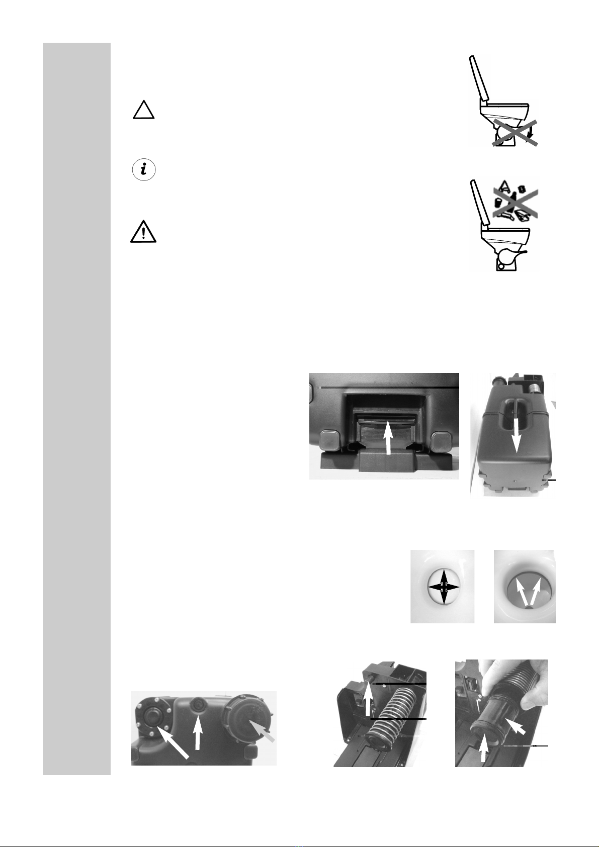
When opera ing he flushing sys em, always keep he sea lid closed.
Do NOT press he pedal during cleaning or whils he lid is open.
WARRANTY and CUSTOMER SERVICE
Wa anty a angements a e in acco dance with EC Di ective 44/1999/CE and the
no mal conditions applicable fo the count y conce ned. Fo wa anty o othe
se vicing, please contact ou Dometic Se vice depa tment. Any damage due to imp o-
pe use is not cove ed by the wa anty. The wa anty does not cove any modifica-
tions to the appliance o the use of non-o iginal Dometic pa ts;
the wa anty does not apply if the installation and ope ating inst uctions a e not
adhe ed to and no liability shall be ente tained. Pa ts can be o de ed th oughout
Eu ope f om ou Dometic Se vice depa tment. When contacting Dometic Se vice,
please state the model and p oduct numbe s, togethe with the MLC Code, if
applicable. You will find this info mation on the data plate inside the pedal housing.
Damage in ransi
Afte emoving the packaging, check whethe the ef ige ato has been damaged
du ing t anspo tation.
Any damage sustained in t ansit must be epo ted to the t anspo tation company
conce ned no late than seven days afte delive y of the goods.
DESCRIPTION of MODEL
DANGER ATTENTION
22..00
33..00
4.0
11..00
2.1
3.1
VT 2500
Vacuum Toilet va iant
4

OPERATION
Pu ing in o opera ion
Firs check whe her:
the cassette has been inse ted co ectly
the vehicle wate tank has been filled
the powe supply has been switched on (main switch).
Once the powe supply fo the vehicle has been switched on, the toilet is also auto-
matically switched on and a vacuum is p oduced in the system fo the fi st time.
The yellow LED illuminates on the display panel.
Afte app ox. 1 minute this p ocedu e is finished. The green LED illuminates.
By lif ing he pedal allow a li le wa er o en er he oile , so ha he closure on
he base of he recep acle is covered.
Repeat this p ocedu e afte each flushing.
Display panel
If the cassette is full o the ope ating voltage is insufficient, the red LED illuminates
and the system switches off.
I canno be used fur her un il he casse e has been emp ied or he correc
vol age has been res ored.
Flushing he oile
The oile may only be flushed whils he green LED is illumina ed.
To flush, p ess the pedal down on the left side of the toilet. Du ing the
flushing p ocess close he sea lid; this will conside ably educe the
noise.
In o de to be able to use the toilet as often as possible fo one cassette
filling, please economize on the wate and pape . No mally app ox. 0.4 L wate
a e sufficient fo flushing once.
5
YELLOW (pump is run-
ning), do no use oile
GREEN (ready)
RED (casse e full, or
undervol age, oile can-
no be used)
The sys em is ready for opera ion!
55..00
5.1
LED
5.2

Only use commercially available toilet paper with 2 layers.
Since the system always operates under a vacuum and is closed
hermetically, no smell can develop.
Never press the pedal whilst sitting on the toilet or if the
seat lid is open!
For the environment's sake, do not use
any chemicals.
o not dispose any solid or non-dissolving objects
such as plastic cans or paper towels in the toilet. These
items can cause damage or plugging of the system !
Removing the cassette
To remove the cassette, raise the locking latch (A) underneath the grip.
Pull out the the cassette using the carrying grip (B).
When inserting the cassette again,
make sure that it is inserted exactly
in the opening provided and that
after pushing it in, the locking latch
has notched again.
Cleaning
Since the toilet receptacle is made of ceramic material, you can clean it in the same
way as a household toilet.
or cleaning the plastic parts (such as the lid, seat, outer
covering) please only use water with a mild cleaning
agent.If possible, rinse the cassette with fresh water
each time it has been emptied.
To avoid deposits clean also the flush ball ( ig.1) and
the sealing ring ( ig. 2 with the flush ball opened)
Occasional clean the area where the excrements are transferred at the connection
( ig. 3) and on the base station
( ig. 4-5).
5.3
5.4
6
A
A
B
3
45
1
2
For
emptying
open here

Changing he fil er
The filte in the base station must be changed acco ding to the numbe of times it has
been used, at the latest, howeve , afte th ee yea s.
Pu ing ou of opera ion
If the vehicle is not going to be used fo a longe pe iod of time, especially in the
winte months, p oceed acco ding to the following inst uctions:
1. Afte the wate tank has become empty in the no mal way, o the vehicle pump is
switched off and the g een lamp indicating " eady" fo ope ation illuminates, p ess the
pedal without allowing any wate to ente .
2. Repeat this p ocedu e a second time.
3. Then empty and clean the cassette.
4. Inse t the cassette again and tu n off the powe supply.
5. The inlet valve fo the wate flushing (located unde neath the pedal) must
be emptied (see Fig. below).
7
5.5
Ventil
Unsc ew the lock nut and
p ess the pedal with the
wa er feed urned off.
The wate escapes f om the
valve.
Then sc ew on the lock nut
again.
5.4.1
Remove the cove
fil er

Declara ion of conformi y5.6
8


INSTALLATION
The vacuum toilet is intended for installation in caravans or motor homes.
Delivery includes:
Fixation of the rear wall of the base station
66..00
6 1
10
The base plate and the rear wall must be assem-
bled on the same vehicle element!
Toilet Vacuum cassette Base station (complete with
base plate and rear wall)
Display panel with connection cable
1 cap
4 screws and caps
1. The rear wall of the base station is mounted on a level floor at ri ht an les to the
outer door usin all 4 screws.
The floor must be stron enou h to support the wei ht of the cassette.
back front

Fixation of the floor plate of the base station
Fixation of the toilet
Inserting the cassette
11
6 2
1. The floor plate of the base station is fixed to the rear
wall.
The floor has two lu s (A), that have to be pushed
into the respective aps in the rear wall of the base
station.
Make sure that the connection (B) for the carbon
filter fits into the place provided!
2. The floor plate of the base station is screwed to the
floor of the vehicle.
3. The ventilation hose (C) is conducted throu h the
vehicle floor to the exterior.
1. The toilet must be installed horizontally. .
2. Use the screws included in the delivery for fastenin it
to the floor of the vehicle.
3. The screws are then covered with the four caps.
The floor and the cassette are in dovetail desi n.
The cassette can easily be pushed into this openin until the lock in the roove (D) not-
ches.
6 3
6 4
Distance to the rear
wall : min 50 mm
AA
B
C
D
C

Connecting pipes6 5
- The installation of the connectin pipes (DN 40) from the vacuum cassette
to the toilet must be completely airti ht and include a siphon!
- The maximum length of the pipes from the toilet to the cassette is
approx 7 m!
- If the pipes have to be shortened for layin purposes, the place where it is
sawn must be deburred and the pipes chamfered from the outside.
- The laid pipes must be fastened without any strain with a pipe clip (40x15)
approx. every 0.8 m.
- The maximum difference in hei ht of the pipe connections from the toilet to
the cassette must not exceed 0.8 m (see Fi . 1).
Always lay the pipes at right angles!
- The horizontally laid pipes must be installed with an incline of approx. 1°
from the toilet to the cassette (see Fi . 1)!
Correct
installation!
Wrong
installation!
12
Fi . 1
Fi . 2
Fi . shows the complete VT 2500 system
siphon
siphon
LED-display panel
with pipe connection on the ri ht-hand side (pipe connection on the left-hand side, optional)

Water supply
Electrical installation
Electrical installation must be carried
out by qualified personnel only !
The 12V DC connection to the toilet electro-
nics is shown in the adjacent fi ure.
The 2-pole connection cable is connected to
the electronics as shown in the fi ure.
The connection cable must have a cross-
section of at least 4 mm².
The connection cable must be protected by
an 8 amp fuse. The connection should be
made directly to the board battery.
The board battery should be protected by an
undervolta e cut-out.
.
Connection display on the control electronics
6 6
The water supply is provided with
the aid of a pump (this can also be
the pump available in the vehicle)
and a hose connection from the
fresh-water container.
Fasten a hose clamp to the water-supply connection.
6 7
red
(+12V)
white
(ground)
6 7 1
13
display panel
4-strand, coded connection cable
electronic board
electronic board
The 4-strand, coded connection cable (A)
(cable cross-section 1 mm²) is connected to
the circuit board as shown in the fi ures.
A
A
base station

Microswitch connection
Data sheet
Voltage supply: 12 V direct current,
Undervolta e fuse to be provided for on the vehicle.
Current consumption: 1.5 A whilst the pump is runnin
Pump running time: max. 60-70 sec. (dependin on cassette content
and len th of pipes laid)
Total cassette content: approx. 25 litres
Of this cassette content,
excrements: approx. 14 litres
Chemical additives: not required
Toilet paper: use with a max. of 2 layers
Changing the filter: dependin on frequency used, at the latest every
3 years.
Dimensions: toilet 420 x 350 x 430
(H x W x D in mm) base station with container 302 x 269 x 548
6 8
14
6 7 2
For vehicles that are not equipped with a pressu-
rized water system, a toilet with inte rated
microswitch for controllin a pump must be
installed.
The microswitch (A) is connected in the circuit of
the submer ible pump so that the pump is activa-
ted via the microswitch when the pedal is pres-
sed.
Connection cable to the
pump with two wires
A
This connection is not necessary in vehicles with a pressure controlled pump.
area for siphon and pipes dependin on built-
in-situation (ch. 6.5)

Wiring diagram6 9
15
The power supply must comply with the following performance data:
Vehicle battery:
Volta e > 11.5 Volt
Peak current (short-term) 8 Amp. Use slow-actin fuse in the feed line!
These values are reached in the standard vehicle batteries.
Power pack:
When usin a controlled fixed-volta e power pack (e. . for application in weekend homes) one
should similarly make sure that these values are adhered to. Normal rated volta e for power
packs with 13.8 V at 6 A.
The control electronics are equipped with an overload protection (Poly Switch). This fuse protects
the motor a ainst excessively hi h currents (e. . also for older or badly serviced batteries, that
supply less than the required minimum volta e of 11.5 Volt ). Should this fuse be activated (red
LED illuminates on the control display), it is necessary to check the power supply and ensure that
the iven values are adhered to.
After a RESET (short-term interruption of the electric circuit, e. . by removin the cassette) and a
short coolin -down period (approx. 1 min) the system is ready for .

Dometic GmbH
In der Steinwiese 16
D-57074 Sie en
Tel.: +49-(0) 271 / 692-0
Fax.: +49-(0) 271 / 692 - 300
www.dometic.de/caravan
Dometic AB
Tor atan 8
S-17154 Solna
Tel.: +46- 8 501 025 00
Fax.: +46- 8 501 025 98
www.dometic.com
©Dometic GmbH - 2002 - Subject to chan e without notice - Printed in Germany
Table of contents
Other Dometic Indoor Furnishing manuals
Popular Indoor Furnishing manuals by other brands

ROOMS TO GO
ROOMS TO GO HLVN 56135H-40 Assembly instruction

Woodard
Woodard WDC-WOO-9240 Assembly instructions

Relax-A-Lounger
Relax-A-Lounger SOFA Assembly instructions

DITALIA
DITALIA RACK CLIC RC-20 Assembly manual

Furinno
Furinno 11192 Assembly instruction

pottery barn kids
pottery barn kids BELDEN BED manual