Dometic DA20E User manual

USA
SERVICE OFFICE
Dometic, LLC
2320 Industrial Parkway
Elkhart, IN 46516
574-294-2511
CANADA
Dometic, LLC
46 Zatonski, Unit 3
Brantford, ON N3T 5L8
CANADA
519-720-9578
For Service Center
Assistance Call:
800-544-4881
This manual must be read and
understood before installation,
adjustment, service, or mainte-
nance is performed. This unit must
be installed by a qualied service
technician. Modification of this
product can be extremely hazard-
ous and could result in personal
injury or property damage.
Lire et comprendre ce manuel avant de
procéder à l’installation, à des réglages,
de l’entretien ou des réparations.
L’installation de ce produit doit être
effectuée par un réparateur qualié.
Toute modication de ce produit peut
être extrêmement dangereuse et
entraîner des blessures ou dommages
matériels.
AVERTISSEMENT
!
RECORD THIS INFORMATION FOR FUTURE
REFERENCE:
Model Number
Serial Number
Date Purchased
Retailer / Qualied Installer
INSTALLATION
INSTRUCTIONS
MODEL
203(XX)(XX).000(#)
TYPE DA20E
(220V-240V ~, 50 HZ)
ELECTRIC
CASSETTE AWNING
These Instructions must stay with unit. Owner
read carefully.
REVISION
Form No. 3313971.057 08/11
(Replaces 3313971.040)
©2011 Dometic, LLC
LaGrange, IN 46761
3313971.057

2
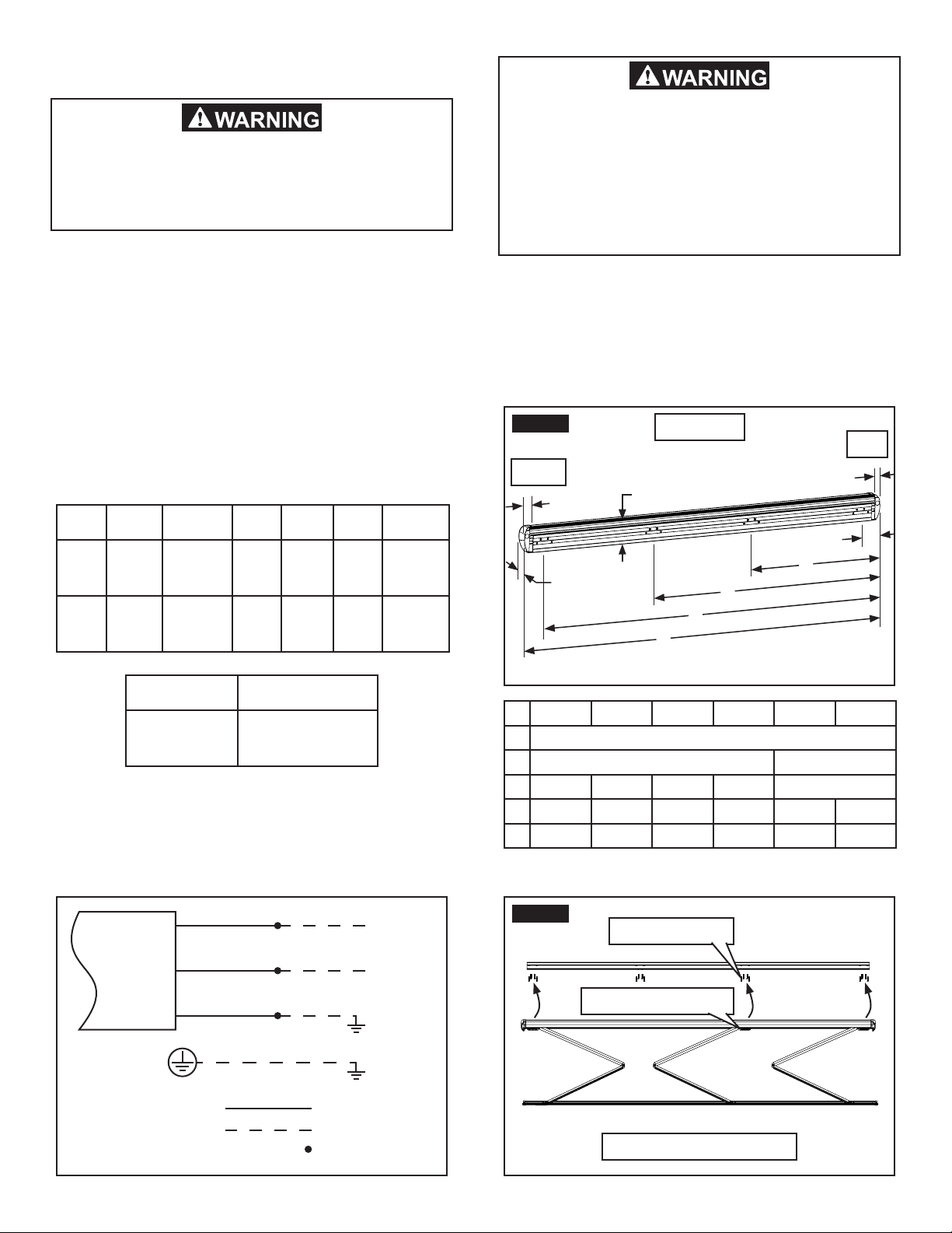
All eld wiring modications should be made in compliance
with the latest edition of IEC 60335-1 and 60335-2, and
any applicable country and local codes.
Required hardware:
2.5 M - 4 M Models Only:
(1) Mounting Bracket
(3) Backing Plate
(12) 10.3 mm O.D. Sleeves
(12) M6 X 50 mm L Carriage Bolt
(12) M6 Split Lock Washer
(12) M6 Flat Washer
(12) M6 Locknut With Nylon Insert
(6) 8-18 X .38 Self Drilling Flat Head Screw
Additional hardware quantities:
4.7 M - 5 M Models only:
(1) Backing Plate
(4) 10.3 mm O.D. Sleeves
(4) M6 X 50 mm L Carriage Bolt
(4) M6 Split Lock Washer
(4) M6 Flat Washer
(4) M6 Locknut With Nylon Insert
(2) 8-18 X .38 Self Drilling Flat Head Screw
Required tools:
3 mm Hex Key
6 mm Hex Key
10 mm Socket (and wrench)
Torque Wrench (with 6 mm Hex Key Socket)
PH Phillips Head Screwdriver (or bit and drill)
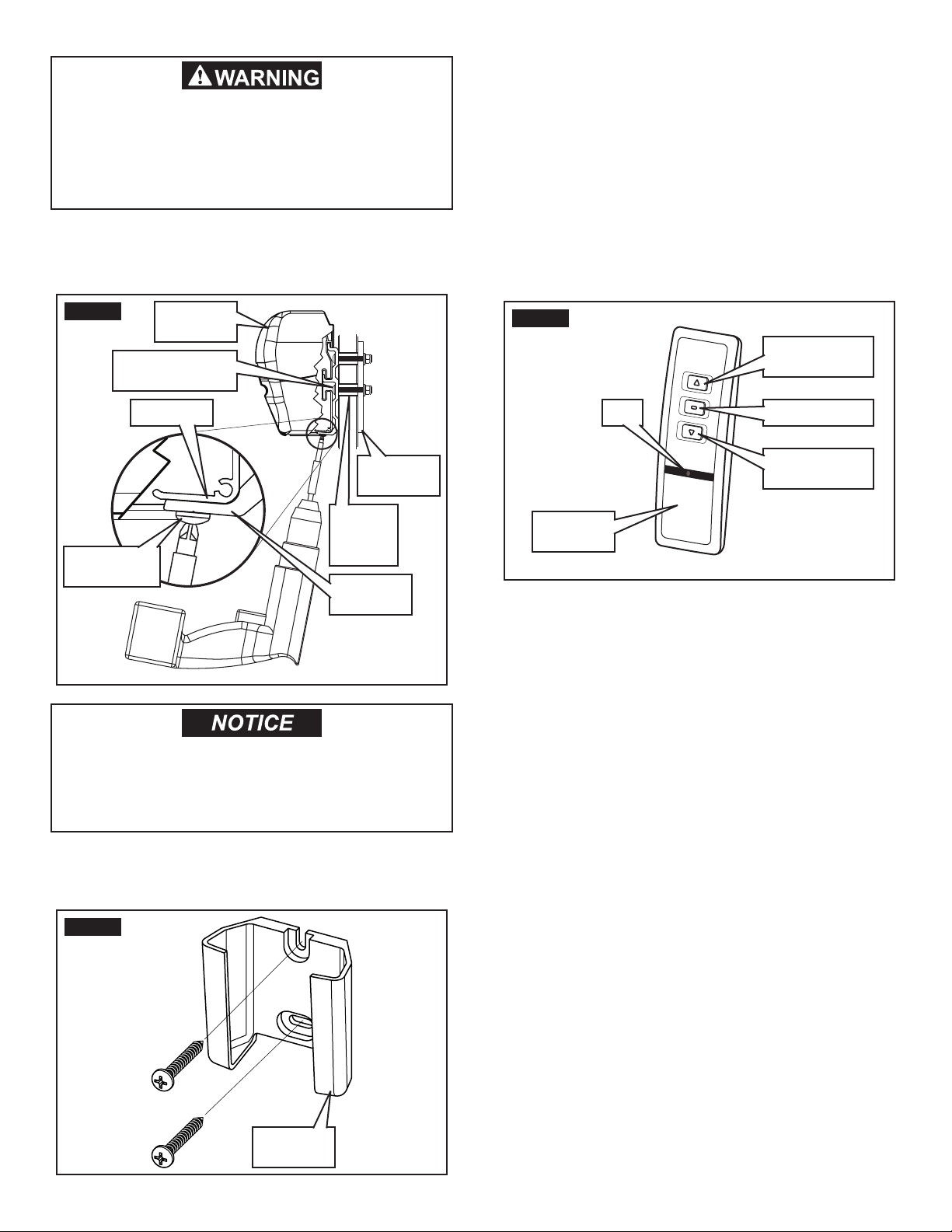
Optional accessories:
3313888.000 Kit, Solar Sensor
3313943.000 Kit, Remote Wall Control
3313981.000 Kit, Remote (additional)
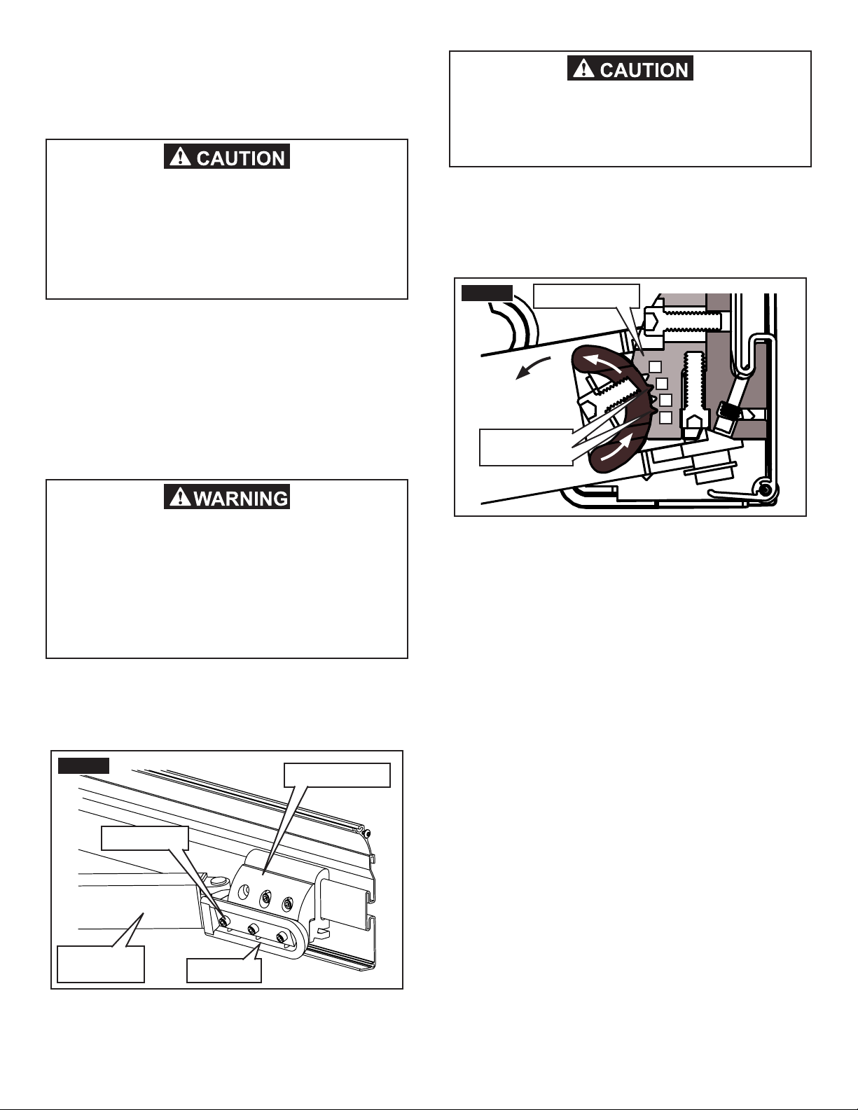
A. Application
The cassette awning is ideal for use on RVs. It is especially
well suited for RVs with an over cab extension where there
is not sufcient surface for a bottom mounting bracket.
Cassette awnings can be installed by one person with
brief help from additional personnel. Use the following
procedure to ensure a properly installed, and properly
functioning awning.
Dometic, LLC reserves the right to modify appearances
and specications without notice.
IMPORTANT SAFETY INSTRUCTIONS
This manual has safety information and instruc-
tions to help users eliminate or reduce the risk
of accidents and injuries.
RECOGNIZE SAFETY INFORMATION
This is the safety alert symbol. It is used to alert
you to personal injury hazards. Obey all safety
messages that follow this symbol to avoid pos-
sible injury or death.
UNDERSTAND SIGNAL WORDS
A signal word, when used with the safety alert
symbol, will identify a safety hazard and its level
of risk for personal injury. A signal word, without
the safety alert symbol, will be used for property
damage messages only.
WARNING indicates a hazard-
ous situation which, if not avoided, could result
in death or serious injury.
CAUTION, used with the safe-
ty alert symbol, indicates a hazardous situation
which, if not avoided, could result in minor or
moderate injury.
NOTICE is used to address
practices not related to personal injury.
GENERAL INSTRUCTIONS
These instructions must be read and under-
stood before installation of this hardware.
This hardware must be installed by a Dometic,
LLC Service Center or a qualied service tech-
nician. Incorrect installation can lead to se-
vere injury. Follow all installation instructions.
Modication of this product can be extremely
hazardous and could result in personal injury
or property damage.
Read and follow all safety instructions for
installation to avoid possible injury or death.

3
2. Wiring Diagram:
B. Specications
IMPACT OR CRUSH HAZARD. Make sure
mounting bolts are located behind each
shoulder assembly (lateral arm attachment)
to provide proper support. Otherwise, the cas-
sette awning may become unstable and could
bend or collapse. Failure to obey this warning
could result in death or serious injury.
FIG. 2
4.7 M - 5 M Model Shown
Mounting Bolts
Shoulder Assembly
FIG. 1
A
B
C
35 mm
35 mm
Back View
Right
Left
D
E
162 mm
102 mm
2.5 M 3 M 3.5 M 4 M 4.7 M 5 M
A163 mm
BN/A 1546 mm
C1284 mm 1545 mm 1757 mm 2007 mm 2954 mm
D2405 mm 2926 mm 3351 mm 3850 mm 4577 mm 4850 mm
E2568 mm 3089 mm 3515 mm 4013 mm 4740 mm 5013 mm
1. Power source may be utility power, or inverter of
either the modied sine wave or pure sine wave
type.
Note: If an inverter is used, it must comply with all appli-
cable electrical codes.
The motor is protected by a thermal switch, which will dis-
able the motor temporarily to prevent overheating. If this
occurs, the motor will require a cool-down period (which
will vary based on ambient temperature) before it will
operate again.
ELECTRICAL SHOCK HAZARD. Installer must
provide proper earthing for equipment. Fail-
ure to obey this warning could result in death,
serious injury, or property damage.
Voltage
Frequency
Power Torque Speed
Protection
Index
Power
Supply
220V ~
to
240V ~
50 Hz 180 W N/A N/A N/A
Motor
Rating 230V ~ 50 Hz 170 W 25 Nm 17
RPM IPX4
Duty Cycle
Unit Rating Intermittent
2 1/2 minutes
3. Mounting bracket (bolt pattern) spacing. See
FIG. 1.
a. 2.5 M - 4 M models require (3) sets of bolts.
b. 4.7 M - 5 M models require (4) sets of bolts.
Note: Spacing must provide mounting bolts behind each
shoulder assembly (lateral arm attachment). See FIG. 2.
Brown
Blue
Green/Yellow
Active
Neutral
Earth
Awning Case
Earth Screw Case Earth
Factory Wire
Installer Supplied Wire
Installer Supplied
Wire Connector

4
FIG. 5 RV Wall
Thickness (-) 2 mm
(Cut Line)
(+) 14 mm
(Cut Line)
Carriage
Bolt
Sleeve
FIG. 4 RV Wall
(Structure Not Shown)
Sleeves (Provided
-Installer Cut To Length)
Mounting
Bracket
Backing Plate
(Provided)
Carriage Bolts (Provided
-Installer Cut To Length)
PROCEDURE
A. Install Cassette Awning
1. Determine location of awning.
a. Allow for a minimum of 12 mm clearance at
top and sides of awning case.
Note: Additional clearance is recommended to allow ease
of access for servicing.
b. Avoid location that interferes with entry door
swing when awning is completely extended.
Note: Awning is factory preset for a 5° fabric slope, but it
may be adjusted for a 15° slope. Allow for sufcient clear-
ance to accommodate awning pitch (slope).
For a 550 mm entry door, the approximate clearance should
be 50 mm for 5° slope, and 150 mm for 15° slope.
Make sure entry door will open without inter-
ference when awning is completely extended.
Make sure the mounting surface is at and
vertical. Any tilt in the mounting surface will
cause tilt in the lead rail. Failure to obey this
notice could result in property damage.
IMPACT OR CRUSH HAZARD. Make sure RV’s
structure will safely and securely support aw-
ning before installation. Otherwise, the cas-
sette awning may become unstable and could
bend or collapse. Failure to obey this warning
could result in death or serious injury.
FIG. 3
Mounting Bracket
RV Wall
(Solid Structure Shown)
PINCH HAZARD. Awning must be installed at
a height of more than 2.5 M above ground or
other level that could provide access to it. A
horizontal distance of at least 400 mm must
be maintained between the fully open awning
and any permanent object.
Failure to obey these cautions could result
in injury.
c. Find a solid structure in RV wall for support
of mounting bracket (if possible). See FIG. 3.
Important: A backing plate and sleeves (provided)
are needed inside RV wall to strengthen awning sup-
port. See FIG. 4.
Note: The 10.3 mm O.D. sleeves and M6 carriage bolts
provided will t up to 36 mm RV wall thickness. If RV wall
is thicker than 36 mm, longer carriage bolts and sleeves
will be required. Cut sleeves and carriage bolts (Grade 8.8
minimum) to t RV wall as necessary. Repair threads (at
cut) on carriage bolts. See FIG. 5.

5
8. With a mechanical lift, or the help of additional
personnel, lift the cassette awning up near the
mounting bracket.
Note: Do NOT hook onto mounting bracket until wiring is
routed.
IMPACT OR CRUSH HAZARD. Do not over-
tighten fasteners. Applying too much torque
may cause fasteners to fail, and could allow
awning to collapse. Failure to obey this warn-
ing could result in death or serious injury.
2. Using the mounting bracket as a template, mark
it’s position and all hole locations. See FIG. 3.
3. Mark a line between the (2) outside top holes,
and the (2) outside bottom holes. See FIG. 6.
6. Install mounting bracket securely with provided
backing plates, sleeves, carriage bolts, locknuts,
and washers. Tighten to 4 ±0.5 Nm torque. See
FIG. 3 and 4.
7. Apply sealant along entire top edge of mounting
bracket where it meets the RV’s wall. See FIG. 7.
LIFTING HAZARD. Use proper lifting tech-
nique and control when lifting awning. Failure
to obey this caution could result in muscle
strain, back injury, or property damage.
Before drilling, make sure there are no ob-
stacles inside RV wall (cables, wires, gas
pipes, etc.).
5. Pre-drill 12 mm clearance holes for sleeves on
the marked (intersecting) locations. See FIG. 3
and 6.
Mounting bracket must be installed on a at
surface, and leveled to ensure proper function
and appearance.
To help prevent water leakage, always use
sealant (Sikaex 252 or similar) on clean parts
and surfaces where fasteners enter RV’s side
wall or roof.
4. Verify horizontal lines are level, then mark verti-
cal lines from all remaining holes to intersect the
marked horizontal lines. See FIG. 6.
Note: Due to the nature of long extruded parts, the mount-
ing bracket may be slightly bowed. Some hole locations
may be above or below the marked horizontal lines.
FIG. 6
Horizontal Line
Between Outside
Bottom Holes
Horizontal Line
Between Outside
Top Holes
Vertical
(Intersecting)
Line
FIG. 7 Sealant

6
13. Ensure awning is securely hooked onto mounting
bracket, then carefully extend approximately 300
mm. Verify awning’s back rail is fully contacting
mounting bracket’s vertical surface. See FIG. 11.
IMPACT OR CRUSH HAZARD. Make sure aw-
ning is securely mounted, and hooked onto
mounting bracket. Failure to obey this warn-
ing could cause awning to dislodge and fall,
and could result in death or serious injury.
FIG. 11
Back Rail Mounting
Bracket
No Gap
FIG. 10
Mounting Bracket
Carriage Bolt
(Cut To Length)
RV Wall
(Structure Not Shown)
Backing
Plate
Cassette
Awning
Sleeve
(Cut To
Length)
12. With the help of additional personnel, hook aw-
ning onto mounting bracket. See FIG. 10.
11. Make wiring connections in compliance with all
applicable electrical codes. See FIG. 9.
Important: A means to disconnect awning (contact
separation in all poles) from power supply mains must
be incorporated into the xed wiring in compliance
with all applicable electrical codes.
FIG. 8 RH End Plate
Earth Screw
FIG. 9
108 mm
16 mm
RH End Cap
Awning
Motor Wiring
ELECTRICAL SHOCK HAZARD. Remove
power from RV before making wiring con-
nections. Wire to a 220V-240V ~, 50 Hz circuit
with correct polarity, and in compliance with
all applicable electrical codes.
A separate breaker or fuse with a switch be-
tween mains circuit and awning, plus a sepa-
rate earthing wire must be installed.
Do not allow wiring to rub against sharp
edges. If supply wiring is damaged, it must
be replaced by a Dometic, LLC Service Center
or a qualied service technician.
Properly seal all wiring against weather and
moisture.
Failure to obey these warnings could result
in death, serious injury, or property damage.
9. If an inverter is installed, verify that installation is
in compliance with all applicable electrical codes.
Important: Location of inverter must be dry and free
of combustible chemicals.
10. Install a separate copper earthing wire (in compli-
ance with all applicable electrical codes) between
earth and earth screw on RH end plate under RH
end cap. See FIG. 8.

7
14. Place and tighten the self drilling screws through
mounting bracket and into cassette awning’s
back rail. See FIG. 12.
IMPACT OR CRUSH HAZARD. Do not operate
or leave awning unattended until it is securely
fastened to mounting bracket. Failure to obey
this warning could cause awning to collapse,
and could result in death or serious injury.
15. Locate a suitable location for remote holster that’s
protected from weather and other adverse condi-
tions, and install with (2) screws. See FIG. 13.
Do not expose remote and remote holster to
weather, extreme temperatures, or long hours
in direct sunlight. Failure to obey this notice
could result in property damage.
FIG. 13
Remote
Holster
FIG. 12
Self Drilling
Screw
Backing
Plate
Cassette
Awning
Mounting
Bracket
Back Rail
Sleeve
(Cut To
Length)
Carriage Bolt
(Cut To Length)
B. Verify Motor And Remote Functionality
1. With power applied to awning, press the open
button (down arrow) briey on awning remote.
Awning should extend to its out limit. See
FIG. 14.
Note: If awning does not respond to remote, verify LED
lights momentarily (on remote) when button is pressed. If
LED does not light, install new batteries.
If awning still does not respond, does not extend to its out
limit, extends too far (fabric not taut), or stops when button
is released the motor and remote may need to be reset.
(See “Reset Motor And Remote” in Operating Instructions.)
2. Press the close button (up arrow) briey on
awning remote. Awning should retract until it’s
closed. See FIG. 14.
Note: If awning does not close or stops when button is
released, the motor and remote may need to be reset.
(See “Reset Motor And Remote” in Operating Instructions.)
3. Press the stop button briey (while awning is ex-
tending or retracting) to stop travel. See FIG. 14.
FIG. 14
Open Button
(Down Arrow)
Awning
Remote
Stop Button
Close Button
(Up Arrow)
LED

8
D. Adjust Fabric Slope (If Desired)
FIG. 17
5° Slope
(Factory Preset)
1. Extend awning far enough to access shoulder
(approximately 300 mm). See FIG. 18.
Any adjustment of this hardware must be per-
formed by a Dometic, LLC Service Center or
a qualied service technician only. Improper
adjustment of this product can be extremely
hazardous and could result in personal injury
or property damage.
The cassette awning is factory preset for a 5° fabric slope
to help accommodate water runoff. Alternatively, the awning
may be set for a 15° fabric slope if there is adequate door
clearance, etc. See FIG. 17.
FIG. 18
Lateral Arm Assembly
Strapping
300 mm
Near Shoulder
Assembly
Near Wrist Assembly
Lead Rail
C. Verify Wind Sensor Functionality
1. With awning extended to its out limit, shake
the lead rail up and down 75-100 mm for ap-
proximately 8 seconds (to simulate wind vibra-
tion). Awning should retract until it’s closed. See
FIG. 15.
Note: If awning does not close, install new batteries in wind
sensor (located on inside surface of lead rail). An LED will
light momentarily (on circuit board) when new batteries
are installed.
Verify potentiometer sensitivity is set to “3” (factory preset),
and that sensor is installed properly on sensor base. See
FIG. 16.
If awning still does not close, sensor may need to be reset.
(See “Reset Wind Sensor” in Operating Instructions.)
FIG. 15
Lead Rail
FIG. 16
Battery
Compartment
LED
Wind
Sensor
Potentiometer
Sensor Base

9
PINCH HAZARD. Make sure power is removed
from awning before working near lateral arm
assemblies. Otherwise, user may accidently
operate awning while work is in progress.
Failure to obey this caution could result in
injury.
7. Tighten cap screws to 15.5 Nm torque to re-clamp
the shoulder to the shoulder base. See FIG. 19.
8. Repeat steps (5) through (7) for each lateral arm
assembly. Remove ties when done.
6. Pivot the lateral arm assembly down (rotate shoul-
der in shoulder base to lower lead rail) until shoul-
der’s keys align with shoulder base’s grooves at
positions “1” and “3”. See FIG. 19 and 20.
PINCH POINT HAZARD. Keep clear of pivot
area when raising or lowering lateral arm
assembly. Failure to obey this caution could
result in injury.
5. Loosen the (3) cap screws (3.5 turns maximum)
clamping the shoulder to the shoulder base on (1)
lateral arm assembly only. See FIG. 19.
IMPACT OR CRUSH HAZARD. Make sure lat-
eral arm assemblies are tied and supported
securely (with lead rail) before loosening
fasteners. Otherwise, the lead rail and lateral
arm assemblies could shift or drop quickly
and unexpectedly. Failure to obey this warn-
ing could result in death or serious injury.
FIG. 20
4
3
2
1
Shoulder’s
Keys
Shoulder Base
FIG. 19 Shoulder Base
Shoulder
Lateral Arm
Assembly
Cap Screws
3. Tie all lateral arm assemblies securely (with fab-
ric strapping or light rope) near shoulder and
wrist. See FIG. 18.
4. Support weight of lead rail and lateral arm as-
semblies securely.
2. Remove power from awning.

10
4. Slightly loosen the (2) cap screws (per lateral
arm assembly) clamping the shoulder base to the
shoulder bracket. See FIG. 22 and 23.
Important: Loosen cap screws just enough to relieve
clamping pressure on components. Do not loosen any
farther.
FIG. 23
Shoulder
Base
Shoulder
Bracket
Cap Screws
Adjustment
Screw
IMPACT OR CRUSH HAZARD. Make sure lead
rail and lateral arm assemblies are supported
securely before loosening fasteners.
Do not completely remove fasteners, or
loosen them so far that shoulder base will
disengage from shoulder bracket.
Otherwise, the lead rail and lateral arm as-
semblies could drop quickly and unexpect-
edly, or lateral arm assemblies could extend
to the side, beyond awning perimeter quickly
and unexpectedly.
Failure to obey these warnings could result
in death, serious injury, or property damage.
1. Extend awning far enough to access shoulder
base (approximately 300 mm). See FIG. 22.
FIG. 22
Shoulder Base
Shoulder
Bracket
Cap Screws
Adjustment Screw
PINCH HAZARD. Make sure power is removed
from awning before working near lateral arm
assemblies. Otherwise, user may accidently
operate awning while work is in progress.
Failure to obey this caution could result in
injury.
2. Remove power from awning.
3. Support weight of lead rail and lateral arm as-
semblies securely.
E. Readjust Lateral Arm Assemblies (If
Required)
After fabric slope adjustment, verify that cassette awning
will close without interference. If awning will not close
properly, or if lateral arm assembly’s elbow will not clear
back rail, it will need readjustment. See FIG. 21.
Note: The lateral arm assembly’s elbow should just clear
(slightly above) lower lip of back rail without rubbing. Adjust-
ing too high may interfere with top (awning case), or may
cause shoulder base to contact awning fabric.
Do not allow lateral arm assemblies to rub
against lower lip of back rail when closing,
or against awning fabric when fully opened.
Failure to obey this notice could result in
property damage.
FIG. 21
Elbow Clearance
Lateral Arm
Assembly
Top
Back Rail
Shoulder
Base

11
G. Secure Awning For Travel
Examine installation for imbalance, or signs
of wear or damage to cables and other criti-
cal parts. Any adjustments or repairs must be
performed by a Dometic, LLC Service Center
or a qualied service technician.
1. Operate awning according to the Operating In-
structions to verify all parts are functioning prop-
erly.
2. Secure awning for travel. (See “Close Awning” in
Operating Instructions.)
5. Readjust lateral arm assembly’s closing height.
See FIG. 21, 22 and 23.
a. Apply power to awning.
b. Retract awning until lateral arm assembly’s
elbow meets top and back rail to check for
clearance.
Note: Allow enough gap to access adjustment screw. See
FIG. 23.
c. Turn adjustment screw in shoulder base IN to
raise or OUT to lower lateral arm assembly.
Note: This will also affect the lead rail height. See “Realign
Lead Rail” section to adjust lead rail alignment.
d. When you reach appropriate clearance, ex-
tend awning far enough to access shoulder
base (approximately 300 mm).
e. Remove power from awning.
f. Tighten the (2) cap screws to 15.5 Nm torque
(for each lateral arm assembly) to clamp the
shoulder base to the shoulder bracket.
FIG. 24
Lead Rail
Wrist Pivot
Lateral Arm
Assembly
Top
Adjustment
Screw
RH End
Cap
Wrist Bracket
F. Realign Lead Rail (If Required)
After fabric slope and lateral arm assembly adjustments,
the lead rail may need realignment with top and end caps.
See FIG. 24.
1. Check alignment of lead rail against top and end
caps.
2. With power applied to awning, extend awning far
enough to access adjustment screw in wrist pivot
(approximately 150 mm).
3. Remove power from awning.
4. Tilt lead rail, by turning adjustment screw in wrist
pivot (for each lateral arm assembly), until align-
ment appears correct.
a. Turn clockwise to tilt lead rail forward.
b. Turn counter-clockwise to tilt lead rail back.
5. Apply power to awning.
6. Retract awning again to check alignment of lead
rail against top and end caps.
7. Repeat steps (2) through (6) as necessary.
Table of contents
Other Dometic Lawn And Garden Equipment manuals