9
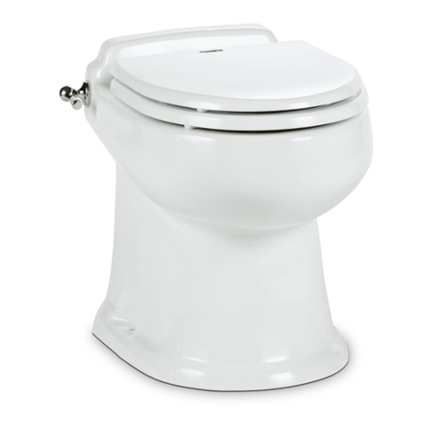
Clean your SeaLand toilet regularly for maximum sanitation and operating ef-
ciency. You can clean it just as you would a household toilet.
For stubborn stains, use SeaLand Toilet Bowl Cleaner (Fig.
A). It’s made especially for use with SeaLand toilets. Where water is hard, a
build-up of lime may dull the toilet bowl nish. Restore the shine with this cleaner.
If you cannot nd our brand in your area, contact SeaLand Product Customer
Service for your nearest dealer. If it is not available, you can also use most non-
abrasive bathroom and toilet bowl cleaners (Bar Keeper's Friend®spray cleaner,
Clorox®toilet bowl cleaner, SaniFlush®toilet bowl cleaner, etc.). Please follow
label instructions.
After an extended time, mineral deposits from hard water
can build up under the edge of the bowl seal, resulting in a slow leakdown of
water from the bowl. To prevent this mineral build-up, periodically clean under
the bowl seal with SeaLand Toilet Bowl Cleaner (Fig. B).
1. Shut off electrical power supply to toilet.
2. Apply cleaner onto a cleaning tool (soft-bristle brush, etc.). Open the ush
ball by pressing on Manual Override Lever. Scrub under entire seal, making
sure to scrub all parts of seal that come into contact with ush ball.
3. Remove cleaning tool. Wait 2-3 minutes.
4. Use water and cleaning tool to rinse cleaner and loosened deposits away.
5. Turn on electrical power to close ush ball. Water will ow into bowl when
power is restored to toilet.
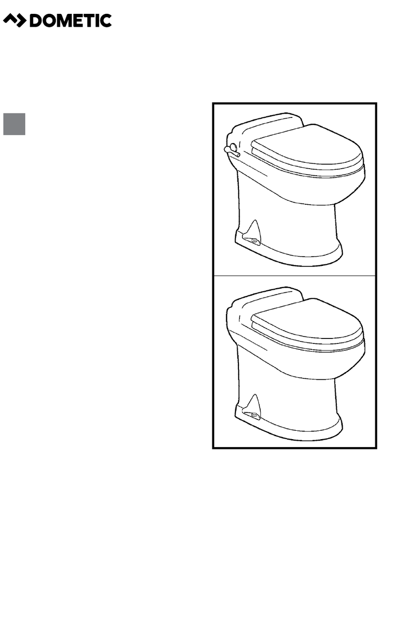
Pull up the ush handle (4300 model) or push "Add Water" switch (4400 model) until the desired water level
is attained.
Push the ush handle down (4300 model) or push "Flush" switch (4400 model) for a moment, then release it.
In the event of a power failure, you can use the "Manual Override Lever" to open the ush ball (for toilet use)
until power is restored. The ush ball will close only when electrical power is restored.
WINTERIZING
At the end of each traveling season, the SeaLand toilet system must be winterized for storage. The following
procedure should be used:
1. Pump out waste holding tank.
2. Thoroughly ush toilet system with fresh water.
3. Drain freshwater tank.
4. Add freshwater antifreeze to freshwater tank.
5. Flush freshwater antifreeze and water mixture through toilet and into the waste holding tank. Each installation
is different so amounts may vary. User discretion is required to assure adequate protection.
6. Turn off electrical power.
The use of freshwater antifreeze that contains alcohol will result in damage to your sanitation
system. Only use propylene glycol freshwater antifreeze that
®DO NOT USE
®®
®
®®®
® Bar Keepers Friend is a registered trademark of SerVaas
Laboratories Inc.
® Clorox, Pine-Sol and Soft Scrub are registered trademarks of
The Clorox Co.
® Comet is a registered trademark of Prestige Brands International.
® Drano is a registered trademark of S.C. Johnson & Son Inc.
® Pam is a registered trademark of ConAgra Foods.
® Sani-Flush is a registered trademark of Reckitt Benckiser Inc.
® Teon is a registered trademark of DuPont Co.
® WD-40 is a registered trademark of WD-40 Company.
