INSTALLATION:
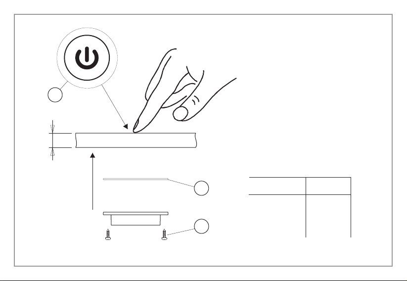
- CAPSENS FW can be installed directly on the installation surface (figure 1)
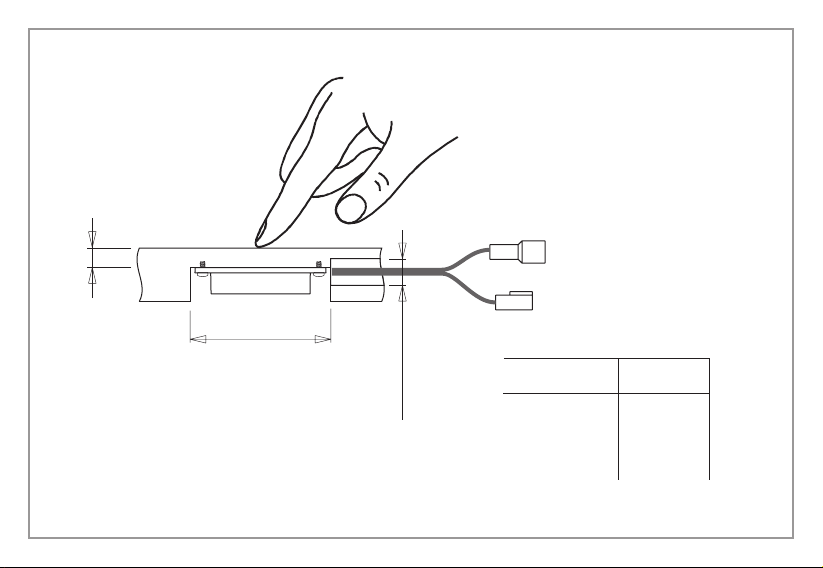
or by boring a ø ≥50 mm hole as illustrated in figure 2. To anchor it use
the screws (A) or the double sided adhesive (B) included.
- For installations with the cables in an axial position, if necessary bore a
ø ≥12mm hole on the installation surface in correspondence to the
cabling as illustrated in the example shown in figure 2.
- In the package an adhesive window (C) that can be applied on the side
opposite the CAPSENS FW installation surface in order to help identify
activation of the switch.
- Connect the CAPSENS FW only to a safe power supply with 12Vdc or
24 Vdc stabilised voltage (sold separately) and with power at least 10%
higher than the total load. For the total load calculation check the plate
data printed on the product label.
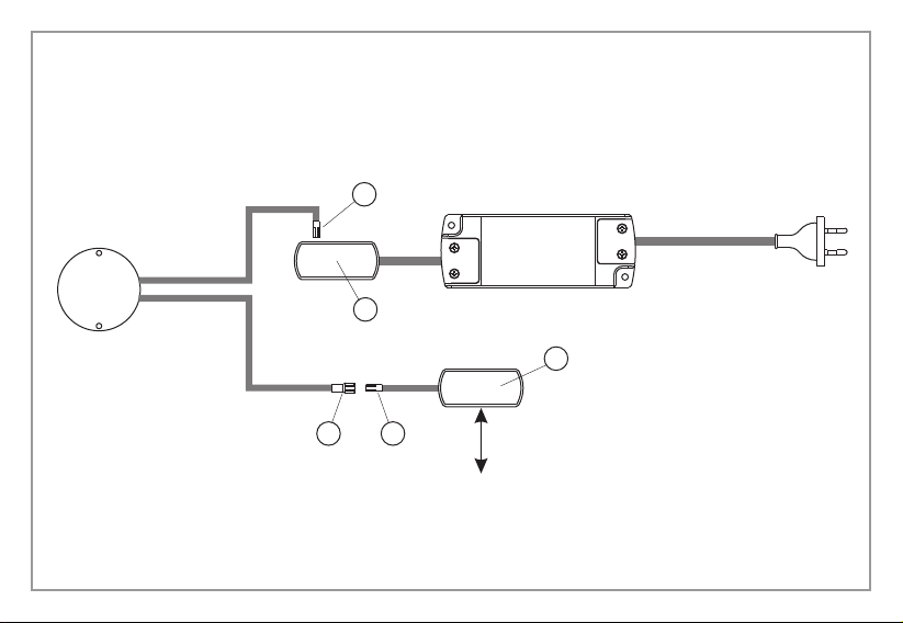
- For connection to a 12Vdc power supply (figure 3) insert the CAPSENS FW
input cable (IN) connector (D) to one of the free slots on the distributor (E)
on the secondary cable of the Converter; then connect the CAPSENS FW
output cable (OUT) connector (F) to the MiniPlug (H) distributor cable
connector (G) which has 12 slots for the connection of 12Vdc LED lighting
devices.
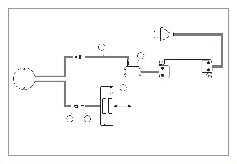
- For connection to a 24Vdc power supply (figure 4) an adaptor cable (I) and
the Micro24 (L) distributor provided in the package must be used. Connect
the CAPSENS FW input cable (IN) connector to the adaptor cable (I) and
then to one of the free slots on the distributor (E) on the secondary cable
of the power supply; then connect the CAPSENS FW output cable (OUT)
connector (F) to the Micro24 (L) distributor cable connector (G) which has
10 slots for the connection of 24Vdc LED lighting devices.
- DOMUS Line guarantees the product only if powered with a Converter
supplied by us.
TECHNICAL SPECIFICATIONS
Input voltage: 12–24Vdc
Output voltage: 12–24Vdc
Maximum applicable load: 30W (with 12Vdc power supply)
60W (with 24Vdc power supply)
WARNINGS
Safety is guaranteed is these instructions are followed and therefore
they must be kept. Installation may require qualified personnel to be
involved. Before proceeding with installation of the device ensure that
the environmental conditions are in compliance with and suitable for
the product characteristics. Before any operation on the device remove
mains power.
CAPSENS FW is an electronic capacitive switch designed to be installed
on the back of surfaces such as wood, plastic, glass and other non
metallic materials, both opaque and transparent and a maximum
thickness as indicated on the table in figure 1 and figure 2; the
information is approximate and the sensitivity of CAPSENS FW can
increase or decrease in relation to the composition and characteristics
of the materials. For materials other than those shown on the table
such as, for example, granite, marble and composite materials, we
recommend making a preliminary test prior to installation in order to
ensure that the device works properly. CAPSENS FW must not be
applied on metallic surfaces. CAPSENS FW allows LED devices that
operate at 12Vdc or 24Vdc to be controlled without direct contact
between the hand and the switch but only with the surface under which
it is installed. The area of activation corresponds to a surface of about
ø 50 mm in correspondence to the device.
INSTALLATION MANUAL EN