Safety Instructions
Important safety notes
Concerning symbols used on the extraction unit and referred
to within this manual.
Danger
Refers to an immediately impending danger. If the danger is
not avoided, it could result in death or severe (crippling)
injury. Please consult the manual when this symbol is
displayed.
Warning
Refers to a possibly dangerous situation. If not avoided it
could result in death or severe injury. Please consult the
manual when this symbol is displayed.
Caution
Refers to a possibly harmful situation. If not avoided,
damage could be caused to the product or something in its
environment.
Important (Refer to manual)
Refers to handling tip and other particularly useful
information. This does not signify a dangerous or harmful
situation. Refer to manual when this symbol is displayed.
Electrical Safety
The 3D Print Pro 3 has been designed to meet the safety
requirements of the Low Voltage Directive 2006/95/EC
(previously numbered 73/23/EEC)
Warning
When working with the pump/motor housing open, Live
230/115 volt mains components are accessible. Ensure that
the rules and regulations for work on live components are
always observed.
Important
To reduce the risk of fire, electric shock or injury:
1. Always isolate the system from the mains power
supply before removing the pump/motor access
panel.
2. Use only as described in this manual.
3. Connect the system to a properly grounded outlet.
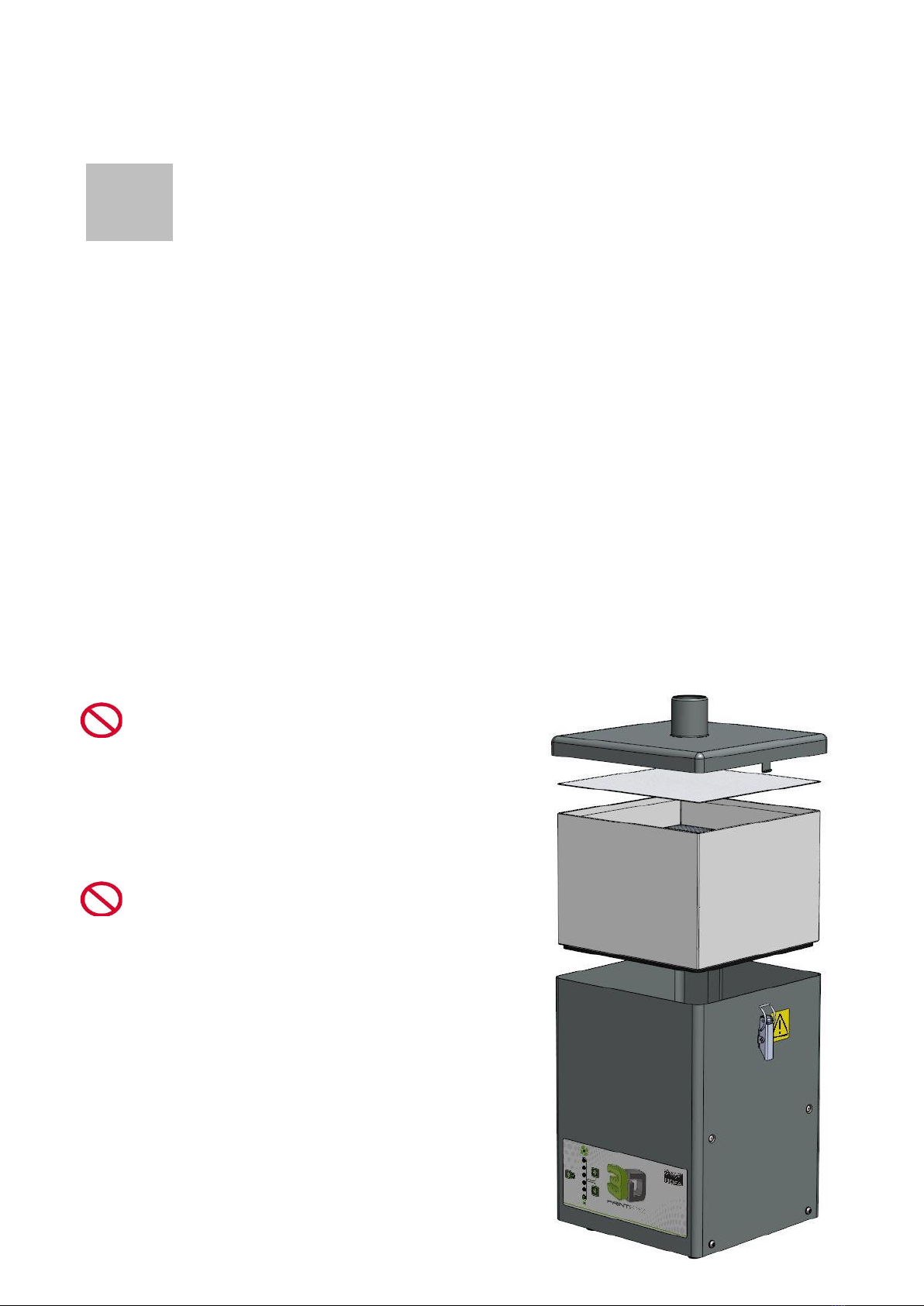
Dangers to eyes, breathing and skin
Once used, the filter within the 3D Print Pro system may
contain a mixture of particulates, some of which may be
sub-micron size. When the used filters are moved it may
agitate some of this particulate, which could get into the
breathing zone and eyes of the operative. Additionally,
depending on the materials being used, the particulate may
be an irritant to the skin.
This unit should not be used on processes with sparks of
flammable materials or with explosive dusts and gases,
without implementation of additional precautions.
Caution: When changing used filters always wear a mask,
safety shoes, goggles and gloves.
Carbon selection
Please note that the media within the filter fitted in the 3D
Print Pro 3 is capable of adsorbing a wide range of organic
compounds. However, it is the responsibility of the user to
ensure it is suitable for the particular application it is being
used on.
BOFA Technical Service
If problems arises with your 3D Print Pro unit please contact
us:
•Visit our website at www.bofa.co.uk for on-line help.
•Or contact the helpline on +44 (0) 1202 699 444,
Mon-Fri, 9am-5pm.
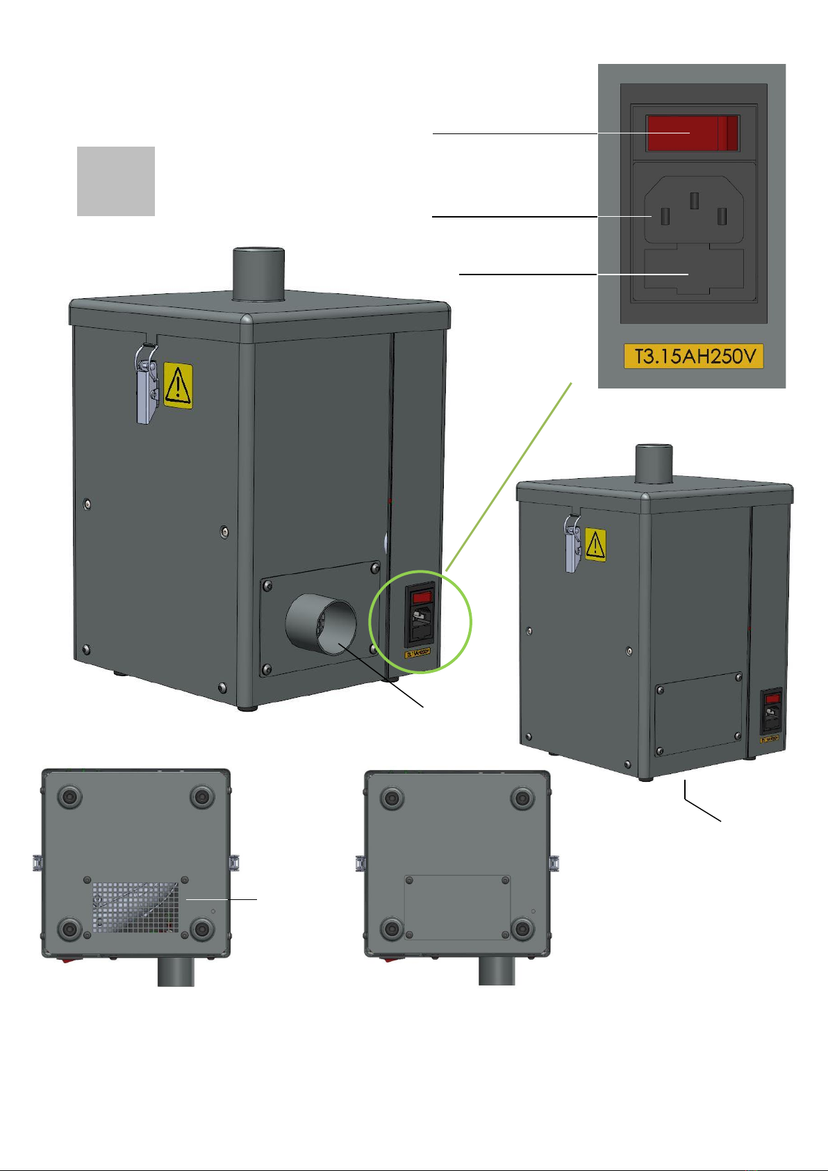
Serial Number
For future reference, fill in your system details in the space
provided. The serial number is on the rating label located on
the side/rear of the unit.
Serial Number: