manuals.online logo
Brands
  1. Home
  2. •
  3. Brands
  4. •
  5. Beninca
  6. •
  7. Gate Opener
  8. •
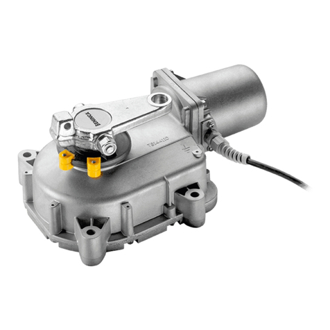
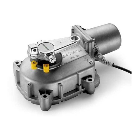
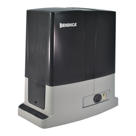
  9. Beninca DU.IT14N Installer manual

Beninca DU.IT14N Installer manual

DU.IT14N
L8542112
Rev. 01/05/05
APRICANCELLO ELETTROMECCANICO
ELECTROMECHANICAL GATE OPENER
ELEKTROMECHANISCHE AUTOMATION FÜR SCHIEBEGITTER
AUTOMATISATION ÉLECTROMÉCANIQUE POUR GRILLES
ABRECANCELA ELECTROMECANICO
ELEKTROMECHANICZNY OTWIERACZ BRAM
Manual istruzioni e catalogo ricambi
Operating instructions and spare parts catalogue
Betriebsanleitung und Ersatzteilliste
Livret d’instructions et catalogue des pieces de rechange
Manual de instrucciones y catálogo de recambios
Książeczka z instrukcjami i katalog części wymiennych
UNIONE NAZIONALE COSTRUTTORI
AUTOMATISMI PER CANCELLI, PORTE
SERRANDE ED AFFINI
2
3
Herstellerklärung
(gemäß EG-Richtlinie 89/392/EWG, Artikel 4.2 und Anhang II, sub B.)
Verbot der Inbetriebnahme
Hersteller: Automatismi Benincà SpA.
Adresse: Via Capitello, 45 - 36066 Sandrigo (VI) - Italia
erklärt hiermit, daß: Antriebe für Drehügeltore DU.IT14N.
• vorgesehen ist zum Einbau in eine Maschine oder mit anderen Maschinen zu einer Maschine im Sinne der Richtlinie 89/392/EWG,
inklusive deren Änderunge, zusammengefügt werden soll;
• aus diesem Grunde nicht in allen Teilen den Bestimmungen dieser Richtlinie entspricht;
• den Bestimmungen der folgenden anderen EG-Richtlinien entspricht:
Direttiva bassa tensione 73/23/CEE, 93/68/CEE.
Direttiva compatibilità elettromagnetica 89/336/CEE, 93/68/CEE.
und daß:
• folgende harmonisierte Normen (oder Teile/Klauseln hieraus) zur Anwendung gelangten:
EN 61000-6-3, EN 61000-6-1, EN 60335-1.
und erklärt des weiteren daß die Inbetriebnahme solange untersagt ist, bis die Maschine oder Anlage, in welche diese Maschine
eingebaut wird oder von welcher sie eine Komponente dasteilt, als Ganzes (d.h. inklusive der Maschine, für welche diese Erklärung
ausgesteilt wurde) den Bestimmungen der Richtlinie 89/392/EWG sowie dem entsprechenden nationalen Reschtserlaß zur Umsetzung
der Richtlinie in nationales Recht entspricht, und die entsprechende Konformitätserklärung ausgestellt ist.
Benincà Luigi, Responsabile legale.
Sandrigo, 10/10/2005.
Declaration du fabricant
(Directive 89/392/CEE, Article 4.2 et Annex II, Chapitre B)
Interdiction de mise en service
Fabricant: Automatismi Benincà SpA.
Adresse: Via Capitello, 45 - 36066 Sandrigo (VI) - Italia
Déclaire ci-apres que: lʼautomation pour portails ouvrants DU.IT14N.
• est prévue pour être incorporée dans une machine ou être assemblée avec dʼautres machines pour consituer une machine couverte
par la directive 89/392/CEE, modiée;
• nʼest donc pas conforme en tout point aux dispositions de cette directive;
• est conforme aux dispositions des directives CEE suivantes:
Direttiva bassa tensione 73/23/CEE, 93/68/CEE.
Direttiva compatibilità elettromagnetica 89/336/CEE, 93/68/CEE.
et que:
• les (parties/paragraphes) suivants des normes harmonisées ont été appliquées:
EN 61000-6-3, EN 61000-6-1, EN 60335-1.
et déclare par ailleurs quʼil est interdit de mettre la machine en service avant que la machine dans laquelle elle sera incorporée ou
dont elle constitue une parte ait été considerée et declarée conforme aux dispositions de la Directive 89/392/CEE et aux législations
nationales la transposant, cʼest-à-dire formant un ensemble incluant la machine concernée par la présente déclaration.
Benincà Luigi, Responsabile legale.
Sandrigo, 10/10/2005.
4
5
Fig.1
133
112
200 220 335
Dimensioni d’ingombro
Overall dimensions
Abmessungen
Dimensions d’encombrement
Dimensiones exteriores
Wymiary gabarytowe
Dati tecnici Technical data
Technische Daten Donnees technique
Datos técnicos Dane techniczne DU.IT14N
Alimentazione
Potenza assorbita
Corrente assorbita
Coppia
Rapporto di riduzione
Classe isolamento
Peso max anta
Tempo per compiere 90°
Lunghezza max. anta
Temper. funzionamento
N° manovre consecutive
Grado di protezione
Protezione termica
Rumorosità
Condensatore
Lubricazione
Peso motoriduttore
Peso cassa
Power supply
Absorbed rating
Absorbed current
Torque
Reduction ratio
Insulation class
Max. wing weight
90° rotation time
Max. wing width
Operating temperature
N° contin. manoeuvres
Protection degree
Thermal protection
Noise level
Capacitor
Lubrication
Gearde motor weight
Casing weight
Speisung
Leistung
Strom-Verbrauch
Drehmoment
Untersetzungsverhältnis
Isolierklasse
Max. Flügelwicht
90° Öffnungszeit
Max. Flügellänge
Laufzeit
N. Vorgänge hintereinan.
Schutzgrad
Thermoschutz
Geräuschentwicklung
Kondensator
Schmierung
Getriebemotor Gewicht
Deckel Gewicht
Alimentation
Puissance absorbée
Courant absorbé
Couple
Démultiplicatione
Classe d'isolement
Poids max. porte
Temps emp. pour 90°
Longueur max. porte
Température de fonct.
N. manoeuvres conséc.
Degré de protection
Protection thermique
Bruit
Condensateur
Lubrication
Poids motoréducteur
Poids caisson
Alimentación
Potencia absorbida
Corriente absorbida
Empuje
Relación de reducción
Clase de aislamiento
Peso máx. de hoja
Tiempo para abrir 90°
Longitud máx. hoja
Temperatura funcionam.
N° maniobras consec.
Grado de protección
Protección térmica
Ruido
Condensador
Lubricación
Peso motor
Peso caja
Zasilanie
Pobór mocy
Pobór prądu
Moment obrotowy
Przełożenie redukcji
Klasa izolacji
Max ciężar skrzydła bramy
Czas na wykon. przes.do 90°
Max długość skrzydła bramy
Temper. podczas pracy
Nr. kolejno następ. manew.
Stopień ochrony
Ochrona termiczna
Hałaśliwość
Kondensator
Smarowanie
Ciężar siłownika
Ciężar obudowy
230 Vac
230W
1,6 A
450 Nm
0,0007
F
500 kg
≈ 20 s
3 m
-20°C/+70°C
15
IP57
130°C
<70dB (a)
9µF
Grasso GR LP1
11,6 kg
8,6 kg
6
7
B
Fig.2
Fig.3
Standard.
Standard.
Standard.
Standard.
Standard.
Standard.
Interno.
Inside.
Innenraum.
Intérieur.
Interior.
Wnętrze obudowy
Apre.
Open.
Öffnen.
Ouvre.
Abre.
Otwarcie
Apre.
Open.
Öffnen.
Ouvre.
Abre.
Otwarcie
Posizione motoriduttore.
Reduction gear position.
Stellung Getriebemotor.
Position motoréducteur.
Posición del motorreductor.
Pozycja siłownika
Posizione motoriduttore.
Reduction gear position.
Stellung Getriebemotor.
Position motoréducteur.
Posición del motorreductor.
Pozycja siłownika
Anta.
Gate wing.
Torügel.
Porte.
Hoja.
Skrzydło bramy.
Anta.
Gate wing.
Torügel.
Porte.
Hoja.
Skrzydło bramy.
Anta.
Gate wing.
Torügel.
Porte.
Hoja.
Skrzydło bramy.
Anta.
Gate wing.
Torügel.
Porte.
Hoja.
Skrzydło bramy.
SS
V
105° 105°
95° 95°
R
R
Muro.
Wall.
Wand.
Mur.
Muro.
Mur
Muro.
Wall.
Wand.
Mur.
Muro.
Mur
Muro.
Wall.
Wand.
Mur.
Muro.
Mur
Muro.
Wall.
Wand.
Mur.
Muro.
Mur
Apre.
Open.
Öffnen.
Ouvre.
Abre.
Otwarcie
Apre.
Open.
Öffnen.
Ouvre.
Abre.
Otwarcie
6
7
Fig.4
Fig.5
Fig.6
Vite TCEI M6x35 (in dotazione).
Screw TCEI M6x35 (supplied).
Schraube TCEI M6x35 (beiliegend).
Vis TCEI M6x35 (fournies).
Tornillo TCEI M6x35 (suministrados).
Śruba TCEI M6x35 (w wyposażeniu.
Vite TCEI M6x30 (in dotazione).
Screw TCEI M6x30 (supplied).
Schraube TCEI M6x30 (beiliegend).
Vis TCEI M6x30 (fournies).
Tornillo TCEI M6x30 (suministrados).
Śruba TCEI M6x30 (w wyposażeniu).
Curare l’allineamento tra la cerniera superiore ed il perno.
Align the top hinge with the pivot.
Oberes Scharnier und Zapfen sind aufeinander auszurichten.
Soigner l’alignement entre la charnière supérieure et le pivot.
Cuidar la alineación entre la bisagra superior y el perno.
Dbać o równopadłość linii pomiędzy górnym wpustem a sworzniem.
Gruppo di traino.
Drive unit.
Zuggruppe.
Entrainement.
Grupo de arrastre.
Zespół ciągnący.
Saldare accuratamente.
Weld accurately.
Sorfältig schweißen.
Souder parfaitement.
Soldar cuidadosamente.
Przyspawać dokładnie.
Gruppo di traino.
Drive unit.
Zuggruppe.
Entrainement.
Grupo de arrastre.
Zespół ciągnący.
Biella motore.
Motor connecting rod.
Motorpleuel.
Bielle moteur.
Biela del motor.
Korbowód silnika.
Leva di collegamento.
Connection lever.
Anschlußhebel.
Levier de liaison.
Leva de acoplamiento.
Dźwignia łącząca.
Sfera.
Ball.
Kugel.
Bille.
Esfera.
Łożysko kulkowe
Perno della cassa.
Pivot of the casing.
Zapfen des Kastens.
Pivot du caisson.
Perno de la caja.
Czop skrzynki obudowy.
8
9
Apre.
Open.
Öffnen.
Ouvre.
Abre.
Otwarcie
105°
95°
Apre.
Open.
Öffnen.
Ouvre.
Abre.
Otwarcie
Anta in appoggio.
Leaning gate leaf.
Anliegende Tür.
Porte appuyée.
Puerta apoyada.
Skrzydło oparte.
Fermo meccanico.
Mechanical stop.
Mechanisch Endanschlag.
Arrêt mécanique.
Tope mecánico.
Blokada mechaniczna.
V
1÷2 mm
Montaggio standard.
Standard assembly.
Standardmontage.
Montage standard.
Montaje standard.
Montaż standard.
Montaggio interno.
Inside assembly.
Innere Montage.
Montage interne.
Montaje interno.
Montaż wnętrza.
V
Fig.7
Fig.8
Fermo meccanico.
Mechanical stop.
Mechanisch Endanschlag.
Arrêt mécanique.
Tope mecánico.
Blokada mechaniczna.
8
9
4x1
4x1,5
3x1,5 min
230 V AC
4x1,5
RG 58
2x1
2x1
2x1,5
34
2
1
1
2
5
6
N.B.: Tenere separati i cavi di potenza da quelli ausiliari.
N.B.: The power cables must be kept separated from the auxiliary cables.
Wichtig: Leistungskabel von Hilfskabeln getrennt halten.
N.B.: Séparer les câbles de puissance des câbles auxiliaires.
N.B.: Tener separados los cables de potencia de los auxiliares.
Uwaga: Trzymać oddzielnie przewody zasilania od przewodów dodatkowych.
Legenda:
1 Motoriduttore DU.IT14N, cassa DU.CNI
2 Fotocellule SC.P30QI (da incasso), SC.P30QE (da esterno)
3 Selettore a chiave ID.SC o ID.SCE (da esterno) o tastiera digitale ID.PTD
4 Lampeggiante ID.LUX
5 Antenna LO.W1N o LO.W1LUX (quarzata)
6 Centrale elettronica DA.93AM
Legenda:
1 Motoreducer DU.IT14N, box DU.CNI
2 Photo-electric cells SC.P30QI (built in) SC.P30QE (external)
3 Key selector ID.SC or ID.SCE (external) or digital keyboard ID.PTD
4 Flash-light ID.LUX
5 Antenna LO.W1N or LO.W1LUX (quartz)
6 Electronic gearcase DA.93AM
Zeichenerklärung:
1 Getriebemotor DU.IT14N, Kasten DU.CNI
2 Fotozelle SC.P30QI (eingelegt), SC.P30QE (außenliegend)
3 Schlüssel-Selektor ID.SC oder ID.SCE (außenliegend) oder Digital-Tastatur
ID.PTD
4 Blinker ID.LUX
5 Antennne LO.W1N oder LO.W1LUX (Quartz)
6 Elektroschrank DA.93AM
Légende:
1 Moteur-réducteur DU.IT14N, caisson DU.CNI
2 Photocellule SC.P30QI (encustiée) - SC.P30QE (suillée)
3 Selecteur à clé ID.SC ou ID.SCE (d’extérieur) ou clavier digital ID.PTD
4 Clignotant ID.LUX
5 Antenne LO.W1N ou LO.W1LUX (au quartz)
6 Centrale électronique DA.93AM
Leyenda:
1 Motorreductor DU.IT14N, caja DU.CNI
2 Fotocélula SC.P30QI (de empotrar), SC.P30QE (de supercie)
3 Selector a llave ID.SC o ID.SCE (de supercie) o teclado digital ID.PTD
4 Relampagueador ID.LUX
5 Antena LO.W1N o LO.W1LUX (cuarzada)
6 Central electrónica DA.93AM
Opis:
1 Siłownik DU.IT14N, obudowa DU.CNI
2 Fotokomórki SC.P30QI (do wbudowania), SC.P30QE (zewnętrzne)
3 Pilot kluczowy ID.SC lub ID.SCE (od zewnątrz) lub klawiatura z przyciskami
ID.PTD
4 Światło migające ID.LUX
5 Antena LO.W1N lub LO.W1LUX (kwarcowana)
6 Centralka elektroniczna DA.93AM
10
11
Pos. Denominazione - Description - Bezeichnung - Dénomination - Denominación - Określenie Cod.
1Gruppo di traino Drive unit Zugeinheit
Gr. d'entrainem.
Gr. de tracción Wóżek ciągnący
9686319
2Sblocco Release Entblockung Déblocage Desbloqueo Zespół odblok.
9686282
3Calotta motore Motor cup Motor Deckel Calotte moteur Estator Silnik
9686294
4Carter trasmis. Transm. guard Gehäuse Carter Caja transmis. Karter
9686284
5Ingranaggio Gear Zahnrad Engrenage Engranaje Koło zębate
9686322
6Coperchio Cover Deckel Couvercle Tapa Karter
9686286
7Vite senza ne Worm screw Zahnrad Vis sans n Tornillo sin n
Śruba dwustronna 9686287
8Albero motore Motor shaft Welle Arbre moteur Eje motor Wał silnika
9686288
1
2
8
3
4
7
6
5
18
19
DU.IT14N
Handbuch für den Verbraucher
Sicherheitsvorschriften
• Nicht im Öffnungsbereich verweilen.
• Kinder nicht mit den Steuerungen oder in der Nähe des Tores spielen lassen.
• Bei Funktionsausfällen nicht versuchen, den Schaden selber zu beheben, sondern den Techniker rufen.
Von Hand Bedienung und Notbetrieb
Bei Strom- oder Betriebsausfall kann zur manuellen Torbetätigung wie folgt vorgegangen werden (siehe Ab-
bildung):
1Schutzdeckel T vom Schloß entfernen.
2Schlüssel C einfügen und drehen, bis er auf Widerstand stößt.
3Hebel L in eine der beiden Richtungen bis zum Endschalter drehen.
Das Tor kann jetzt mauell geöffnet und geschlossen werden.
Zur Wiederaufnahme der Automatikfunktion, Hebel L in die ursprüngliche Stellung bringen, codierten Schlüs-
sel C drehen und herausziehen und Deckel T wieder schließen. Der erste Betriebsablauf stellt das normale
Funktionieren wieder her.
Wartung
• Monatliche Kontrolle der manuellen Notentriegelung
• Es ist absolut untersagt, selbstständig Sonderwartung oder Reparaturen vorzunehmen, da Unfälle die Folge
sein können; wenden Sie sich an den Techniker.
• Der Antrieb braucht keine ordentliche Unterhaltung aber es ist periodisch notwendig die Leistungsfähigkeit
der Sicherheitsvorrichtungen und die andere Teile des Anlages zu prüfen. Sie könnten durch Abnutzung
Gefaht hervorbringen.
Entsorgung
Wird das Gerät außer Betrieb gesetzt, müssen die gültigen Gesetzesvorschriften zur differenzierten Entsorgung
und Wiederverwendung der Einzelkomponenten, wie Metall, Plastik, Elektrokabel, usw., beachtet werden.
Rufen Sie Ihren Installateur oder eine Entsorgungsrma.
Achtung
Alle Produkte BENINCA’ wurden mit einem Versicherungsschein versehen, der alle eventuellen Schäden an
Dingen oder Personen abdeckt, die durch Herstellungsdefekte hervorgerufen wurden, vorausgesetzt, das
Gerät besitzt die Kennzeichnung EU und es wurden original BENINCA’ Einzelkomponenten verwendet.
Stellung zum automatischen Betrieb.
Stellung zum manuellen Betrieb.
T
L
L
T
C
22
23
DU.IT14N
Książeczka z instrukcjami dla użytkownika
Normy bezpieczeństwa
• Starać się nie przebywać w obszarze posuwu skrzydeł.
• Niedopuścić aby dzieci bawiły się sterownikami lub w pobliżu skrzydeł bramy.
• W przypadku niewłaściwego funkcjonowania nie starać się samemu dokonywać naprawy a powiadomić o fakcie
technika wyspecjalizowanego.
Manewr ręczny i awaryjny
W przypadku zaniku prądu lub awarii, by móc obsługiwać ręcznie skrzydło bramy należy postępować w następujący
sposób (opierać się na wskazaniach podanych na rysunku):
1 Zdjąć zatyczkę”T” zabezpieczającą śruby, nałożoną przez nacisk.
2 Wprowadzić klucz ”C” i przekręcać go aż do napotkania oporu.
3 Pokręcać dźwignię ”L” w jednym z dwóch kierunków aż do końca przesuwu.
W tym punkcie możliwe jest już ręczne otwieranie i zamykanie skrzydła bramy.
By przywrócić działanie automatyczne należy przestawić dźwignię ”L” do pozycji pierwotnej, przekręcić i wyjąć klucz
indywidualny ”C” i nałożyć zatyczkę ”T”; pierwszy manewr przywróci normalne funkcjonowanie.
Konserwacja
• Sprawdzać okresowo sprawność działania ręcznego mechanizmu odblokowującego i bezpieczeństwa.
• Nie starać się w żadnym wypadku dokonywać napraw samemu z racji na możliwość ulegnięcia wypadkowi, w celu
naprawy należy skontaktować się z technikiem wyspecjalizowanym.
• Siłownik nie wymaga normalnej konserwacji, tym niemniej wskazane jest okresowe sprawdzanie sprawności działania
elementów bezpieczeństwa i pozostałych części instalacji, mogących stanowić zagrożenie z racji na stan zużycia.
Eliminacja i demolowanie
W przypadku gdy urządzenie nie nadaje się już do dalszego użytkowania, w celu pozbycia się go należy ściśle
przestrzegać obowiązujących w danym momencie norm prawnych regulujących zróżnicowany rozkład na części i
odzyskiwanie niektórych elementów składowych (metale, plastyk, kable elektryczne, itp.); wskazane jest skontaktowanie
się z instalatorem lub wyspecjalizowaną rmą, autoryzowaną do tego rodzaju prac.
Uwaga
Wszystkie produkty Benincà objęte są polisą ubezpieczeniową na pokrycie szkód poniesionych przez rzeczy lub osoby w
wyniku wad produkcyjnych, pod warunkiem że urządzenia posiadają oznakowanie CE i oryginalne części Benincà.
Pozycja dla działania automatycznego.
Pozycja dla obsługi ręcznej.
T
L
L
T
C
AUTOMATISMI BENINCÀ SpA - Via Capitello, 45 - 36066 Sandrigo (VI) - Tel. 0444 751030 r.a. - Fax 0444 759728

Other manuals for DU.IT14N

3

Other Beninca Gate Opener manuals

Beninca PIXEL User manual

Beninca

Beninca PIXEL User manual

Beninca BOB Installer manual

Beninca

Beninca BOB Installer manual

Beninca BILL30 User manual

Beninca

Beninca BILL30 User manual

Beninca BOB21M User manual

Beninca

Beninca BOB21M User manual

Beninca RI.6MLS Installer manual

Beninca

Beninca RI.6MLS Installer manual

Beninca MS424 Installer manual

Beninca

Beninca MS424 Installer manual

Beninca DU.180N User manual

Beninca

Beninca DU.180N User manual

Beninca RI.15T Installer manual

Beninca

Beninca RI.15T Installer manual

Beninca DU.35L Installer manual

Beninca

Beninca DU.35L Installer manual

Beninca PR.45E Installer manual

Beninca

Beninca PR.45E Installer manual

Beninca THINKY User manual

Beninca

Beninca THINKY User manual

Beninca DU.3524L Installer manual

Beninca

Beninca DU.3524L Installer manual

Beninca BULL 10M Installer manual

Beninca

Beninca BULL 10M Installer manual

Beninca BOB User manual

Beninca

Beninca BOB User manual

Beninca CP.PONY User manual

Beninca

Beninca CP.PONY User manual

Beninca MB24V Installer manual

Beninca

Beninca MB24V Installer manual

Beninca LADY-BE.I Installer manual

Beninca

Beninca LADY-BE.I Installer manual

Beninca DU.IT9N Installer manual

Beninca

Beninca DU.IT9N Installer manual

Beninca BISON 35 OTI L User manual

Beninca

Beninca BISON 35 OTI L User manual

Beninca DIVA.5 User manual

Beninca

Beninca DIVA.5 User manual

Beninca RI.5E Installer manual

Beninca

Beninca RI.5E Installer manual

Beninca DU.IT9 Instruction Manual

Beninca

Beninca DU.IT9 Instruction Manual

Beninca HEADY User manual

Beninca

Beninca HEADY User manual

Beninca BULL 17 OMI User manual

Beninca

Beninca BULL 17 OMI User manual

Popular Gate Opener manuals by other brands

Roger Technology M30 Series INSTRUCTIONS AND RECOMMENDATIONS FOR THE INSTALLER

Roger Technology

Roger Technology M30 Series INSTRUCTIONS AND RECOMMENDATIONS FOR THE INSTALLER

BFT IGEA Installation and user manual

BFT

BFT IGEA Installation and user manual

ZEC Automation PY-800ACU user manual

ZEC Automation

ZEC Automation PY-800ACU user manual

Phoenix Doors Enviro 6S user manual

Phoenix Doors

Phoenix Doors Enviro 6S user manual

Erreka CICLON Series installation manual

Erreka

Erreka CICLON Series installation manual

EUROLAIKAS SL500DC user manual

EUROLAIKAS

EUROLAIKAS SL500DC user manual

DITEC SOF instruction manual

DITEC

DITEC SOF instruction manual

Nice 4024 Instructions and warnings for installation and use

Nice

Nice 4024 Instructions and warnings for installation and use

Airlift Doors Magnaglide Air Opener install guide

Airlift Doors

Airlift Doors Magnaglide Air Opener install guide

GFA ELEKTROMAT SE 9.20 WS-25,40 installation instructions

GFA

GFA ELEKTROMAT SE 9.20 WS-25,40 installation instructions

King gates Slim 1500 instruction manual

King gates

King gates Slim 1500 instruction manual

Proteco leader ta Installation and use manual

Proteco

Proteco leader ta Installation and use manual

DKS 6004 manual

DKS

DKS 6004 manual

Apollo 7100UL installation manual

Apollo

Apollo 7100UL installation manual

Nice MetroKit Instructions and warnings for the fitter

Nice

Nice MetroKit Instructions and warnings for the fitter

Nice ROX600 quick guide

Nice

Nice ROX600 quick guide

Tormatic TAR1 400V Assembly and operating instructions

Tormatic

Tormatic TAR1 400V Assembly and operating instructions

LOCKEY TB200 installation instructions

LOCKEY

LOCKEY TB200 installation instructions

manuals.online logo
manuals.online logoBrands
  • About & Mission
  • Contact us
  • Privacy Policy
  • Terms and Conditions

Copyright 2025 Manuals.Online. All Rights Reserved.