INSTALLATION MANUAL
2) GENERAL OUTLINE
Centralizedgearmotor forbalancedrollerdoors,with adjustable electric opening
and closing limit switches.
Available in two versions, reversible (WIND RMB130B 200 - WIND RMB 170B200)
and irreversible (WIND RMB 130B 200EF), (WIND RMB 170B 200EF) and (WIND
RMB 350B 200 EF), the latter provided with electric brake.
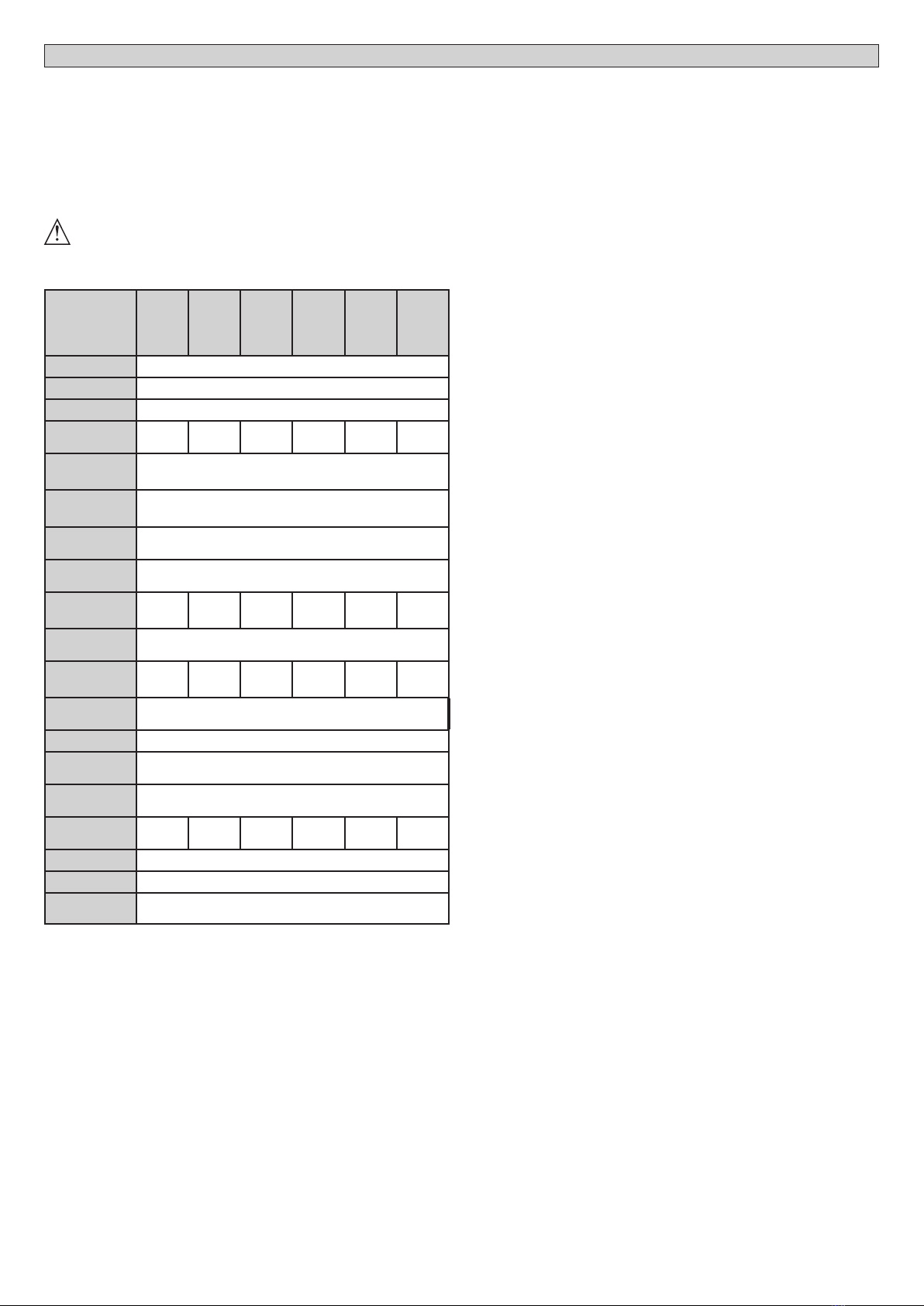
For irreversible versions, the emergency manoeuvre is carried out by means of
a knob attached to a wire.
Thegearmotorisprovidedfor42/48/60mmshaftsanda206/220mmfrictionpulley.
OnlyforUSA: motors intendedforgateswithoutUL Approving
shall not be installed on garage doors.“
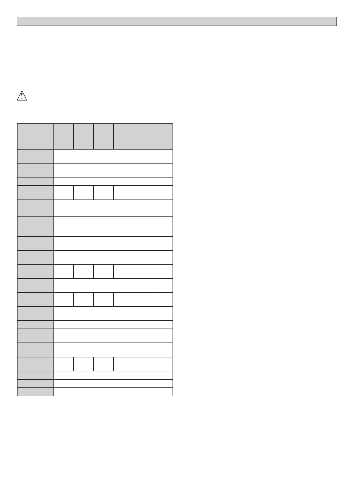
3) TECHNICAL SPECIFICATIONS
WIND
RMB
130B
200
WIND
RMB
130B
200 EF
WIND
RMB
170B
200
WIND
RMB
170B
200 EF
WIND
RMB
350B
200
WIND
RMB
350B
200 EF
Pulleydiameter 206/220 mm
Pipe diameter 60/48/42 mm
Power supply 220-230V 50/60Hz.
Absorbed
power 400 W 400 W 600 W 600 W 1260 W 1260 W
Operating
time 4,5’
Shutter maxi-
mum stroke 6 M
Output shaft
revolutions 10min-1
Thermal
protection present
Capacitor 14 uF 14 uF 16 uF 16 uF 2x16
uF
2x16
uF
Reduction
gear lubrication
Permanent grease
Max. torque 110
Nm
105
Nm
178
Nm
168
Nm
367
Nm
357
Nm
Nominal
torque 5N
Limit devices Electromechanical, incorporated and adjustable
Working
temperature +5°C a + 40 °C
Degree of
protection IP20
Operator
weight 6,9 Kg 7,7 kg 12 kg 12,8 kg 11,5 kg 12,3 kg
Noise level <70dB(A)
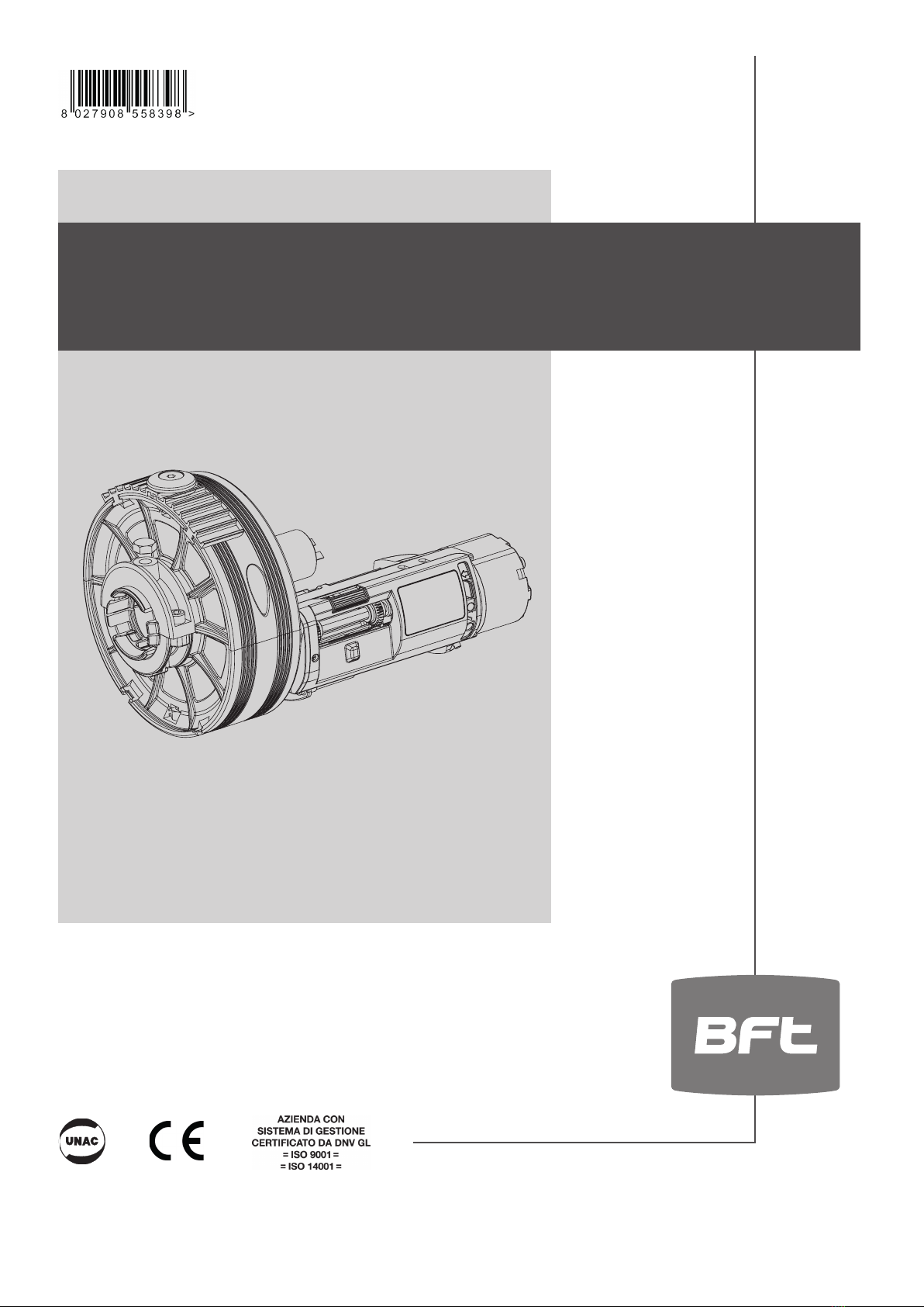
Dimensions See g. B
Maximum
cycle 20 cycles/24 hours
(* other voltages to order)
4) ACCESSORIES
- LCK external safe for release
- X EF1 electronic brake kit to be installed on WIND RMB 130B 200-WIND RMB
170B 200-WIND RMB 350B 200 EF
5) PRELIMINARY CHECKS
Before tting the motor, remove any redundant ropes or chains, and disable any
unnecessary appliance.
Check that the roll-up door characteristics are compatible with the maximum
torque specied and the operating time.
Check the weight of the roll-up door, check the diameter of the spring-holder
boxes and the diameter of the spring-holder shaft.
Choose the model with or without closing lock, depending on which is more
suitable for the type of installation.
NOTE: All the models supplied without an electric brake can be tted with one
at a later time if required. (EF KIT).
Before carrying out the installation, carefully check that:
- the roll-up door structure is sturdy and rigid;
-
the roll-up door slides evenly along its entire stroke, without any friction.
- If the manoeuvre is dicult, grease the sliding tracks.
- Repair or replace the worn or faulty components.
- The motor’s moving parts must be installed at a height greater than 2.5 m
above the oor or other surface from which they may be reached.
- Thegearmotormustbeinstalledinasegregatedandsuitablyprotectedspaceso
that it cannot be reached without the aid of tools.
The operator reliability and safety is directly aected by the condition of
the roll-up door structure.
Motor drive only facilitates operation and does not solve the problems caused
by defective or decient installation or failed maintenance of the roll-up door.
6) INSTRUCTIONS FOR FITTING 1 GEARMOTOR
1)Drillintheshutter’scentralshaft(Fig.C)oneholeØ10mm.inordertheoperator
doesn’t turn, and another Ø 12 mm. for the electric wire. If possible, place the
operator in the centre of the shutter’s shaft in an easy position for opening the
micro-switches lid to make the wire and the regulation of the limit switches.
In case of electric brake, make another drill of Ø 10 mm. for the cable of the
manual release.
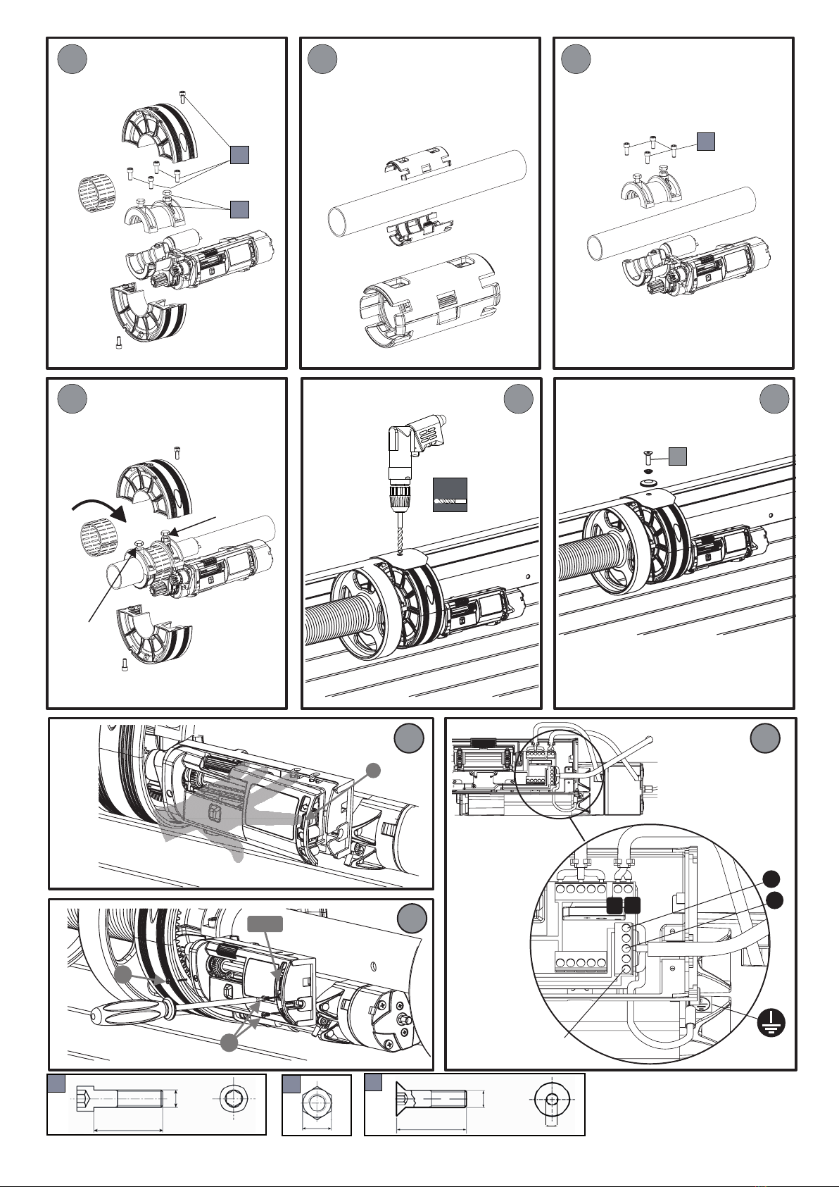
2) Open the pulley unscrewing the M8x25 screws remove the plastic roller band
without folding it and keep it in a clean place. Separate the gear-motor’s body
removing the 4 screws with the 6mm. (g. D). hexagonal wrench.
Couple the two parts of the gear-motor around the door’s shaft and joint them
screwing the 4 screws on the gear-motor’s support (g. E-F).
Tighten the M10x40 screw (Fig. G) entering it into the Ø 10 mm. hole of the
shutter’s shaft.
Put again the plastic roller band in its place.
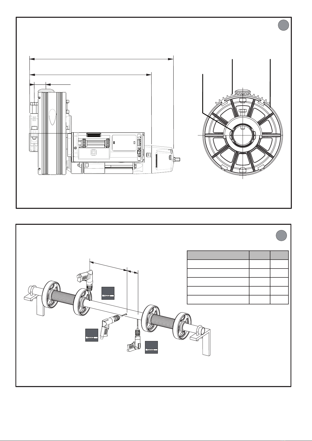
3) The operator should be xed, lined and the pulley must turn freely.
Make a hole Ø 10 mm. in the last canvas of the roll-up door at the same location
of the hole and nut M10 of the pulley (Fig. H). If the roll-up door is waved or
not regular, it is necessary to couple a at metal piece of 1 meter to the pulley.
Travel the electric cable trough the shaft’s hole de Ø 12 mm. Avoiding any
contact with the rotating parts and make the wires. In case of motor with
electric brake travel also the brake cable through the hole of Ø 12 mm. drilled
in the shaft, and mount the manual release.
For a proper release the exible cable of the brake should not do any exag-
gerated curve.
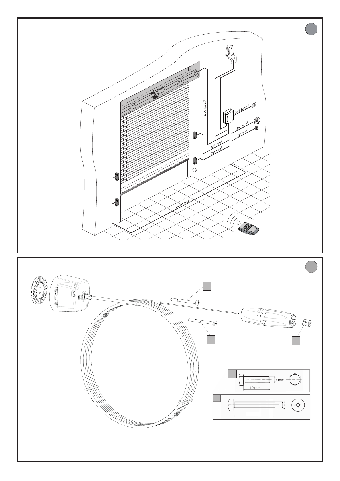
7) ELECTRIC INSTALLATION SETUP
Provide electrical installation complying with the CEI standards actually in force.
The power supply connections must be kept totally separate from the service
connections (photocells, safety edges, control devices etc.).
WARNING! For the connection to the power supply, use a multipolar cable
having minimum 4x1.5 sq mm cross section and complying with the previ-
ously mentioned regulations (for example, if the cable is not protected it
must be at least equal to H07 RN-F, whereas if it is protected it must be at
least equal to H05 VV-F with a 4x1.5 sq mmsection).
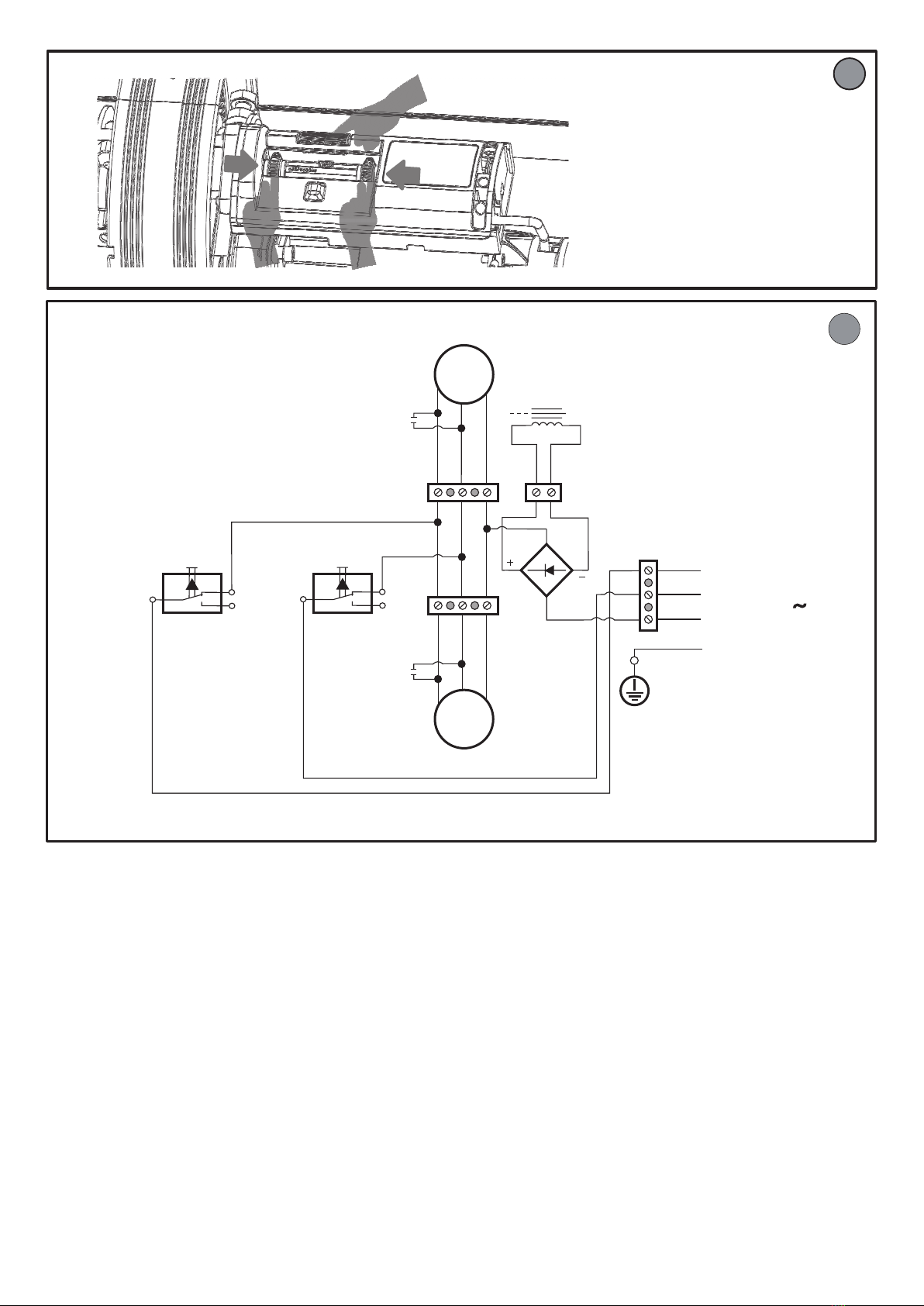
Connect the control and safety devices in compliance with the standards actually
inforce.Fig.Oindicatesthenumber ofconnections andthecrosssectionforpower
supply cables approximately 100 metre long; in case of longer cables, calculate
the cross section for the true operator load. When the auxiliary connections are
over 50-metre long or pass through critical disturbance areas, it is recommended
to decouple the control and safety devices by means of suitable relays.
These are the main components for an operator (g. O):
I) Type-approved omnipolar circuit breaker having adequate capacity,
with at least 3,5 mm contact opening, provided with protection against
overloadsandshortcircuits,suitableforcuttingouttheoperatorfromthe
power supply mains. If not already present, a type-approved omnipolar
switch with a 0.0.3 A threshold should be installed in the circuit before
the operator.
QR) Control panel and incorporated receiver
S) Key selector
AL) Blinker
M) Operator
CS) Safety edge
CC) Edge control device
Ft, F) Pair of photocells
T) 1-2-4 channel transmitter.
8) ELECTRIC WIRE (Fig. J-K)
Todoconnectionsremoversttheprotectinglid ofthelimit switches[Fig.J]Travel
the electric cable through the stung box and do the wires. It is very important
the correct wiring of the common (N blue) and the ground.
SAFETYRULE:theelectriccablemustbe connectedupline withan all-polediscon-
nect device with a minimum contact clearance of 3.5 mm. In the type WIND RMB
130B 200 EF, WIND RMB 170B 200 EF e WIND RMB 350B 200 EF with brake the
electric brake is yet wired. In case of no brake it is compulsory a jumper between
the two terminals [Fig.N]. For tting the electric brake, remove the jumper and
connect the two wires of the reel [Fig.N].
9) CHECKING THE OPERATION DIRECTION (Fig. M)
Place the closing stop collar (Fig.M) next to press the micro-switch. Switch on
8- WIND RMB 200 B
D814092 4BA96_06