SEA SEAGEAR 1180MEC0 Original instructions


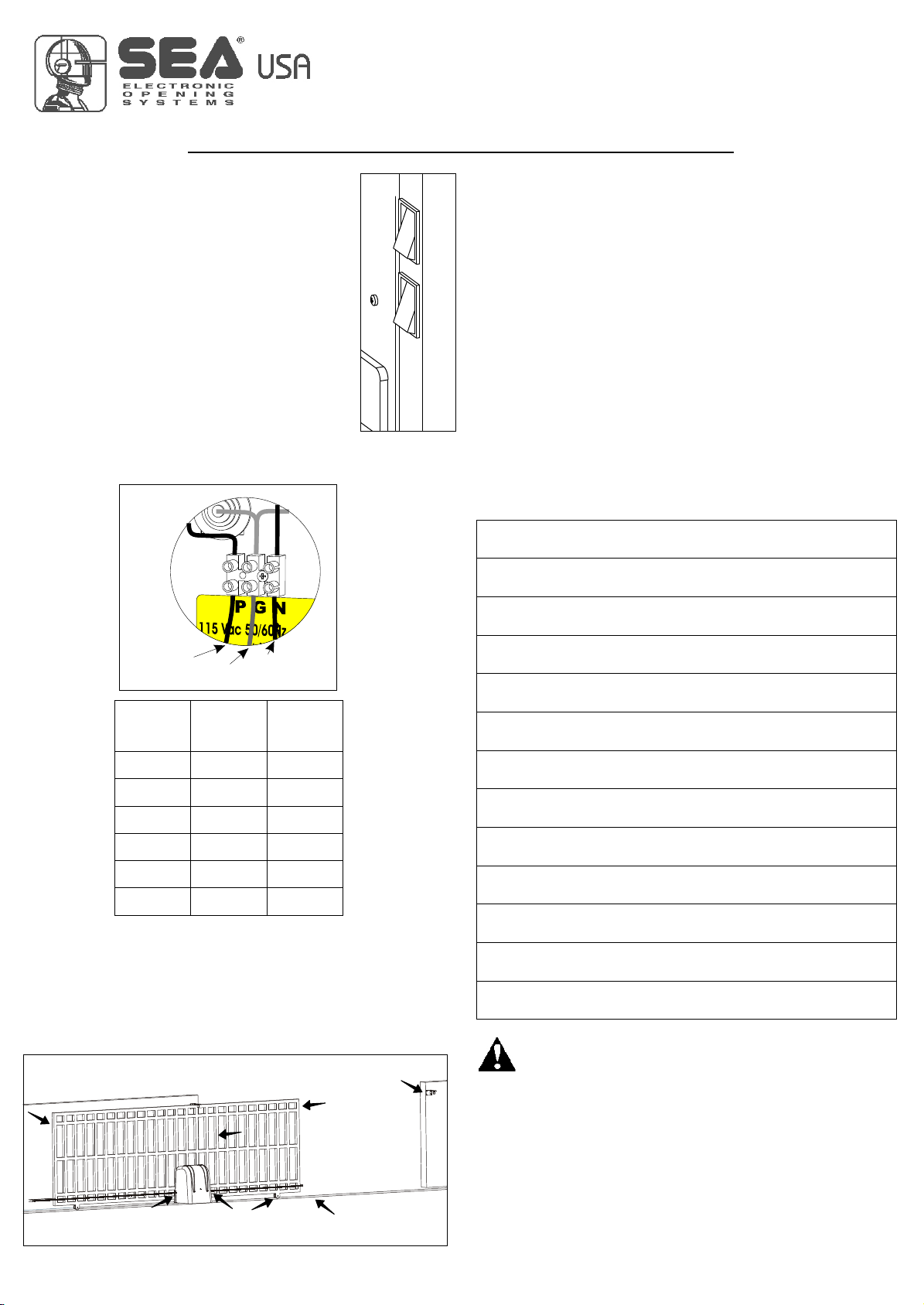


Table of contents
Other SEA Gate Opener manuals

SEA
SEA SURF 350 Reversible User manual

SEA
SEA LIBRA Series Original instructions

SEA
SEA 1110 User manual

SEA
SEA ALPHA 330 STANDARD Original instructions

SEA
SEA full tank User manual

SEA
SEA KITE User manual

SEA
SEA SURF 350 Reversible User manual

SEA
SEA TAURUS BOX 1000 User manual

SEA
SEA SURF K 500 User manual

SEA
SEA SUPER FULL TANK Series Original instructions

SEA
SEA TORG Series Instruction manual

SEA
SEA LEPUS BOX 120V/24V User manual

SEA
SEA SATURN User manual

SEA
SEA HALF TANK User manual

SEA
SEA SURF Series User manual

SEA
SEA LEPUS 800 Instruction manual

SEA
SEA saturn-boxer 2000 User manual

SEA
SEA Boxer 1000 User manual

SEA
SEA GER Instruction manual

SEA
SEA SUPER FULL TANK 20 G6 380V User manual


Popular Gate Opener manuals by other brands

Riello Elettronica
Riello Elettronica CARDIN ACE FAST Instruction handbook

MFZ Ovitor
MFZ Ovitor E6L user manual

FAAC
FAAC 820 installation manual

Maximum Controls
Maximum Controls Max Megatron 1400 Installation and owner's manual

Schartec
Schartec P190 Control Box user manual

Nice
Nice ROBUS350 Instructions and warnings for the fitter

Telcoma
Telcoma ACE 300 Instruction handbook

PNI
PNI MAB300 user manual

Nice
Nice Wingo 5024 Kit Instructions and warnings for installation and use

McConnel
McConnel 3 Wheel Backing Gate Drive owner's manual

Chamberlain
Chamberlain CPS-OPEN4 quick start guide

Chamberlain
Chamberlain THE ROBO SLIDE instruction manual

Avidsen
Avidsen Styrka 310 manual

Dea
Dea Ghost 100 Series Operating instructions and warnings

Elvox
Elvox ES Series instruction manual

Maximum Controls
Maximum Controls MAX F18 Installation and owner's manual

Relcross Door Controls
Relcross Door Controls 9130 installation instructions

Automatic Technology
Automatic Technology NeoSlider NES-500 manual