Doosan NHM Series User manual

Machine Tools
Adjusting & Maintaining ATC
(NHM/NHP Series)


1
NHM/NHP Series NHM/NHPATCE29
Table Of Contents
1. Reset the reference point for ATC servo magazine
.............................................. 2
2. Adjust the position of Magazine sub changer
..................................................... 6
3. Alignment on both ATC and spindle
................................................................ 10
4. Alignment on both ATC and Magazine
............................................................. 13
5. Hydraulic Circuit Diagram of ATC
................................................................... 16
6. Operations on the ATC magazine touch panel
.................................................. 17
7. Tool Search Sequence Chart
.......................................................................... 28
※
Replacing the ATC servo motor ('40Tools' magazine of NHP series )
................... 34

2
NHM/NHP Series NHM/NHPATCE29
※
Adjusting and Maintaining ATC
1. Reset the reference point for ATC servo magazine
※
If the ATC sub changer and the tool pot of the magazine do not align properly due to mis-
position of theATC servo motor, you must restore the reference point of the ATC servo
magazine manually.
1) Prepare the centering fixture
①
: Center Bar
②
: Fixture for Changer Arm
③
: Fixture for Spindle
※
To enable ATC adjustment, you must have the
centering fixture on site as shown in the right.
Servo motor
used for
rotating the tool
magazine
Pot Chain
Tension
Adjusting
Device
1
2
3
Tool Pot
Sub Changer
Changer Arm
Main Changer
Reducing Gear
Box
Tool Carrier Pot

3
NHM/NHP Series NHM/NHPATCE29
2) Install the sub changer fixture
①
Manipulate the magazine manually so
that the tool pot #1 comes to the
changing position.
②
Install the centering fixture between tool pot and sub changer, and move the sub changer
to the pot position of the magazine.
※
If the magazine has the home-position mark
badly misaligned, remove the tool positioning key
in advance. Otherwise, this may cause damage
to the key due to conflicts between sub changer
and fixture while
the sub changer is moving to the
pot position of the magazine.
3) Check the home position of the magazine
Push in the center bar to the centering fixture as
shown, and check to see if the changer arm
aligns with the tool pot correctly. If they are
misaligned, refer to "4) Feed the magazine in
JOG mode" below to move the magazine pot
finely.
Sub
Changer
Centering
Fixture
Centering
Fixture
Center Bar
Centering
치구
Move the tool pot #1
Remove the Key

4
NHM/NHP Series NHM/NHPATCE29
4) Feed the magazine in JOG mode
①
Before moving the magazine, first open the electric cabinet and locate the servo drive that
is specific to the magazine. [-A85]
②
Press the MODE key on the start screen
[r 0000]
of the servo drive to display
[ rd-off ]
.
[ rd-off ]
: Ready to operate the jog run
③
From the
[ rd-off ]
screen, press the down arrow button to display
[ Jog.run ]
.
[ Jog.run ]
: Switch to the jog run mode
④
From the
[Jog.run]
screen, press the SET key to display
[ Jr.0000]
.
[ Jr.0000 ]
: Jog run mode
⑤
From the
[Jr.0000 ]
screen, use the up/down arrow keys
to rotate the magazine in a desired direction. In such a
way, adjust the pot position.
Fine-tune the magazine position
※
If you want to fine-tune the magazine position, set
parameter #27 to a lower value.

5
NHM/NHP Series NHM/NHPATCE29
※
Centering on the magazine chain pot
①
Use the up/down arrow buttons on the
[ Jr.0000 ]
screen, or press the rotation button on
the manual operation panel. While holding the button, insert the center bar into the
centering fixture until it is inserted smoothly.
②
If this doesn't work, refer to "2. Adjust the position of the sub changer of the magazine"
below to align the left and right centers between sub changer and magazine chain pot.
※
When completed, the coordinates of the tool magazine will match with the actual position.
5) Set the Magazine reference position
①
When the centering of the tool magazine's tool pot is completed, press the SET key.
[ Jog.run ]
: Return to the jog run mode
②
In the
[ Jog.run ]
screen, press the MODE key to display
[ rd-off ]
.
[ rd-off ]
: Ready to operate the jog run

6
NHM/NHP Series NHM/NHPATCE29
③
In the
[ rd-off ]
screen, press the up arrow key to display
[ Org.S - - ]
.
[ Org.S - - ]
: Origin mode
④
From the
[Org.S - - ]
screen, press and hold the SET key for 10 seconds. The screen will
blink and switch to
[r 0001 ]
.
[ r 0001 ]
: Return to the start screen
11) Turn off the machine and turn it back on. This is the completion of resetting the reference
point.
2. Adjust the position of Magazine sub changer
1) Adjust the position of the sub changer and the
magazine chain pot
①
Move the tool pot #1 to the changer position,
and install the centering fixture between tool
pot and sub changer.
②
Use the center bar to locate them. Check to
see if the home position of the magazine is
misaligned, or if the sub changer is horizontally
misaligned with the magazine chain pot.
※
This correction work should be performed
together with adjustment of the magazine home
position.
Centering
Bar

7
NHM/NHP Series NHM/NHPATCE29
③
If this is because the sub changer is horizontally misaligned with the magazine chain pot,
use the center bar to check their positions while adjusting the left or right position of the
sub changer using the hydraulic cylinder piston stroke adjustable screw that is located at
the back of the magazine.
※
By factory default, the chain pot can be adjusted using the guide-positioning screws at both
left and right of the chain. However, these screws are rarely used in the field because such a
case is very little likely to happen. This is why we provided an instruction to use the cylinder
stroke adjustable screw for aligning between sub changer and magazine chain pot, instead of
the positioning screws mentioned here.
2) Adjust the position of the sub changer & tool
carrier pot
①
Install the centering fixture between tool carrier
pot and sub changer, move the sub changer to
the waiting pot position, and then move the tool
carrier pot to "POT MAG. SIDE".
Sub
Changer
Centering
Fixture
Tool carrier pot
Chain Pot

8
NHM/NHP Series NHM/NHPATCE29
②
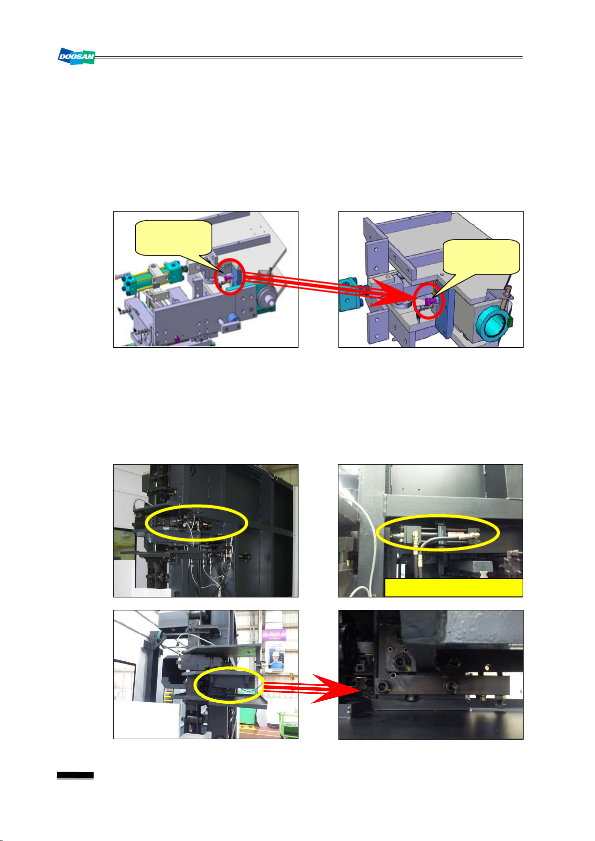
Adjust the left/right position of the tool carrier pot
(↔)
Use the center bar to check the centering position between tool carrier pot and sub
changer. If they are misaligned, use the side stopper of the tool carrier (see the figure
below) to make fine adjustment.
※
If the center bar is not inserted smoothly after adjusting the left/right stopper, refer to
"Adjust the vertical position of the tool carrier pot"
below. If you had adjusted the
stroke of the hydraulic cylinder of the sub changer, this might have happened because the
chain pot was misaligned. You should check out the chain pot first.
③
Adjust the vertical position of the tool carrier pot
(↕)
Use the center bar to check the centering position between tool carrier pot and sub
changer. If they mismatch, loosen the bolts (fixing the cylinder to the tool carrier pot
assembly) and use the vertical adjustment bolts to make correction.
※
However, you seldom need to make vertical adjustment as the tool carrier pot assembly is
tightened up using the pins.
Horizontal
adjustment
stopper
Horizontal
adjustment
stopper
Cylinder
Loosen the cylinder bolts

9
NHM/NHP Series NHM/NHPATCE29
④
Adjust the distance between tool carrier pot and sub changer
Use the gap gauge to measure the distance between centering fixtures as shown, and use
the sub-changer In/Out adjustable stopper to make adjustment.
※
When
adjusting the gap, care must be taken because the gap can be changed due to or as
a result of
"
②
Adjust the horizontal position of the tool carrier pot"
.
※
2mm
is a smallest value. It is advisable to use a 2mm spanner to measure the distance.
※
In most cases where you adjust the position of the sub change and tool carrier pot, you
should make adjustment all together both horizontally and vertically.
2 mm
(BIG PLUS SPINDLE)
Gap adjustable
stopper

10
NHM/NHP Series NHM/NHPATCE29
3. Alignment on both ATC and spindle
1) Check and adjust the spindle orientation
In the current spindle orientation (M19), install the
indicator on the pallet and present the gauge to
the spindle driving key or key place. While moving
the Y axis manually, measure the parallelism
between Y axis and two driving key places. If the
error is beyond 0.05mm, change the parameter
settings to correct the orientation.
▪Orientation setting parameter no. : NC
Parameter #4077
▪Description of Parameter Value: 0.08789˚ per 1 pulse (input range: ±4096)
4096 on the basis of 360˚ for the spindle (90˚ = 1024)
2) Prepare the centering fixture
①
: Center Bar
②
: Fixture for Changer Arm
③
: Fixture for Spindle
3) Remove the spindle driving key and clamp the spindle fixture into the spindle. Perform the
spindle orientation. (M19)
4) In manual oprertion ofATC Changer Arm
In manual operation, move ATC main changer to
the spindle position.
①
In MDI mode, call one of empty pots in the tool
magazine. (
T_ _;
)
②
Move each axis to the respective tool changing
position. (G91 G30 X0 Y0 Z0)
③
Perform
[ ATC Door Open ]
⇒
[ ATC ARM
FORWARD STEP ]
manually in this sequence.
1
2
3
Fixture for
Spindle

11
NHM/NHP Series NHM/NHPATCE29
5) Adjust the position of the changer arm and the spindle
①
Perform
"Pin Unlocking"
in manual operation.
②
Insert the changer arm fixture (see the figure below) into the changer arm.
③
Push in the center bar to the centering fixture
to check if the changer arm aligns with the
spindle both horizontally and vertically. If they
are misaligned, adjust the secondary reference
point of both X and Y axes until they are
aligned correctly.
※
How to adjust the secondary reference point
①
To allow for the axial feed where the changer arm is positioned in the spindle side, change
"Keep Relay K12,2" to 1.
("When Used Maintenance For ATC")
②
Select Handle mode. Use MPG to feed both X and Y axes. Then, check using the center
bar if the changer arm aligns correctly with the spindle.
③
When done, enter the current machine coordinates (X,Y) in Parameter #1241.

12
NHM/NHP Series NHM/NHPATCE29
④
Use the gap gauge to measure the distance between centering fixtures. If the
measurement is greater than the allowance, feed ATC in whole to make adjustment.
※
Unlike 4-digit HM models, the ATC should be fed in whole before you can adjust the gap.
Adjust the horizontal and vertical adjustable bolts as appropriate as to satisfy the
parallelism and gap targets between centering fixtures.
※
Finally, insert a tool into the spindle, and move the
changer arm in contact with the tool manually.
Then, check the inside of the taper area and
make a gap in-between.
▪Correction Target: 0.3
∼
0.5mm
Left/right
Adjustable
Bolt
ATC Fixing
Bolt
2 mm
(BIG PLUS SPINDLE)
0.3∼0.5mm
Forward/backward
Adjustable Bolt

13
NHM/NHP Series NHM/NHPATCE29
4. Alignment on both ATC and Magazine
※
When aligning between ATC and spindle is complete, proceed with aligning ATC and
magazine. If you align ATC with the magazine first, and then with the spindle, they can be
misaligned. Be sure to comply with the sequence.
1) Prepare the centering fixture
①
: Center Bar
②
: Fixture for Changer Arm
③
: Fixture for Spindle
2) Install the fixture
①
First, remove the key from the tool carrier pot,
and install the spindle fixture on the tool carrier
pot.
②
Move the changer arm manually to the side of the spindle, and install the fixture for the
changer arm.
※
The ATC manipulation is the same as in
"3. Align ATC with the spindle"
1
2
3
Install the
fixture
Remove
the key
Install the
fixture
Changer Arm
Tool Carrier
Pot

14
NHM/NHP Series NHM/NHPATCE29
3) Adjust the position of the changer arm & tool
carrier pot
①
Push in the center bar to the centering fixture
to check if the changer arm aligns with the tool
carrier pot both horizontally and vertically.
②
If they misaligned, move the magazine as appropriate by referring to the figure below.
③
Use the gap gauge to measure the distance between centering fixtures. If the
measurement is greater than the allowance, move the magazine as appropriate.
Horizontal
adjustment
Distance
Adjustment
Vertical
adjustment
Make adjustment using the
applicable bolts on 4 vertices of
the magazine base.
Horizontal
Adjustable
Bolts
Distance
Adjustable
Bolts
Height
Adjustable
Bolts

15
NHM/NHP Series NHM/NHPATCE29
④
When done, turn the height bolts by 90
degrees, tighten the ATC fixing bolts and check
the centering again. When the centering is set
properly, tighten up the adjusting bolts and
nuts.
※
In some cases, the operator uses the carrier pot stopper (see the figure below) to adjust the
alignment between ATC and magazine. However, this may result in damage to the product.
Do Never use the stopper marked below to adjust the alignment.
Magazine
Fixing Bolts
Height
Adjustable
Bolts
Tool Carrier
Pot Stopper
Tool Carrier
Pot Stopper

16
NHM/NHP Series NHM/NHPATCE29
5. Hydraulic Circuit Diagram of ATC
S1
(YV31)
S2
(YV32)
S3
(YV33)
S4
(YV34)
Home Position
On Off On Off
Magazine Pot
Position
Off On On Off
Waiting Pot Position
Off
On
Off
On

17
NHM/NHP Series NHM/NHPATCE29
6. Operations on the ATC magazine touch panel
1) Switching screen
①
Manual Operation
②
Machine Information
③
Tool Offset
④
Alarm Information
⑤
I/O Information
O
O
S
A
N
D

18
NHM/NHP Series NHM/NHPATCE29
2) Rotating the tool magazine
①
Select the operation mode
If you press a mode button (Manual or Auto), the
indicator of the selected button will turn on. If you
select a different mode, the current mode will be
released.
: Manual Mode (ATC manual
operation)
: Auto Mode (ATC manual operation
completed)
②
Find the tool number by the loading position
(a) Select the [Manual] mode.
(b) If you select [Tool No.], the number
pad will appear as shown.
(c) Use the number pad to
enter the tool number and press [ENT].
(d) If you press the [Tool Search]
button, the magazine will search for a
matching tool from the nearest.
③
Display of the pot number of the waiting pot
: Displays the number of the pot in the
waiting pot.
④
Manual operation of the magazine
(a) Select the [Manual] mode.
(b) Press the button for a desired direction.
: CW (rotates the magazine clockwise)
: CCW (rotates the magazine counter clockwise)
Start screen of the
touch panel
Start screen of the touch panel
Start screen of the
touch panel
15
Other manuals for NHM Series
1
This manual suits for next models
1
Table of contents
Other Doosan Industrial Equipment manuals
Popular Industrial Equipment manuals by other brands

jost
jost JSK37 Repair instructions

Pursanova
Pursanova Disk Installation

Rockwell Automation
Rockwell Automation Allen-Bradley Guardmaster Minotaur MSR178DP Quick start guide - Troubleshooting

Stahl
Stahl VM125-ex Operating instruction

transnorm
transnorm TS 2800 operating instructions

comarme
comarme GEM XF520 BM Use and maintenance manual