DORIC LEDFLS User manual

LED Light Source
User Manual
Version 2.1.1

Contents
1 Safety Information 3
1.1 Important Safety Information ........................................... 3
1.2 Activation Safety Features ............................................. 4
2 Device Overview 5
2.1 Connectorized LEDs (CLED) ............................................ 5
2.2 Connectorized LEDs - High Power (CLED_HP) ................................. 6
2.3 Combined LEDs (LEDC) .............................................. 7
2.4 LED + Fiber-optic Rotary Joint (LEDFRJ) ..................................... 8
2.5 LED Drivers ..................................................... 10
2.6 LED Fiber Light Source (LEDFLS) ......................................... 12
3 Operation Guide 15
3.1 Connectorized LEDs Setup ............................................. 15
3.2 Combined LEDs Setup ............................................... 16
3.3 LED + Fiber-optic Rotary Joint Setup ....................................... 16
3.4 LED Fiber Light Sources Setup .......................................... 17
3.5 FC Connector Installation ............................................. 18
3.6 Stand-alone mode (without Doric Neuroscience Studio Software) ...................... 19
3.7 Connect to Doric Neuroscience Studio Software ................................ 21
4 Doric Neuroscience Studio 22
4.1 Controls and setings ................................................ 23
4.2 Channel Configuration ............................................... 25
4.3 Acquisition view ................................................... 34
5 Specifications 35
5.1 General specifications ............................................... 35
5.2 Power Tables ..................................................... 39
6 Support 41
6.1 Maintenance ..................................................... 41
6.2 Warranty ....................................................... 41
6.3 Disposition ...................................................... 41
6.4 Contact us ...................................................... 41
2

1
Safety Information
1.1 Important Safety Information
Light-emitting diodes (LEDs) used with sufficiently high power levels can be dangerous for the eyes. NEVER LOOK
directly into the beam exiting from the FC connector of an LED module or from any optical fiber connected to the FC
connector.
Doric LED Drivers are provided with a safety interlock connector on its rear panel (Fig. 1.1a). When the interlock circuit
connector is shorted with the interlock plug, the driver is enabled. The shorting electric wire in the interlock plug can
be removed and replaced by the safety interlock circuit of the laboratory. This safety feature is highly recommended
with UV and infrared (IR) LEDs.
The Power Key Switch is located on the left side of the driver (Fig. 1.1b) to control the use of the device. All light
sources connected to the driver can be enabled only when the power key is properly inserted.
REMINDER
To be enabled, LED Drivers must have its interlock circuit connector shorted
with the interlock plug and the power key properly inserted.
(a) Interlock connector plug connected (b) Properly inserted key switch
Figure 1.1: Safety procedure
3

1.2 Activation Safety Features
The built-in safety features (including the Micro-controller,Key Switch,Interlock Plug and Current Driver) are con-
nected in series in the driver circuits, as shown in the block diagram (Fig. 1.2). This means that if any single safety
feature are not properly in place, the light source cannot be activated.
Figure 1.2: Safety feature block diagram
•The Micro-controller is used to control the light source driver.
•The Key Switch (Safety feature 1) (Fig. 1.1a), located on the left side of the driver, is required to activate any
light source. If removed, no data can be sent from the micro-controller to the Current Driver.
•The Interlock plug (Safety feature 2) (Fig. 1.1b) is used to integrate the driver into an Interlock Circuit.
–The Interlock Plug comes with a small wire short-circuiting it. This wire must be removed before integrating
it into an Interlock Circuit.
–Connect the Interlock circuit in series with the Interlock Plug so the circuit may function properly.
•The Current Driver sends current to any connected light source. If the Key is absent or the Interlock Plug has
an open circuit, it cannot receive signals from the micro-controller, preventing it from sending out current.
Chapter 1. Safety Information 4

2
Device Overview
2.1 Connectorized LEDs (CLED)
Figure 2.1: Connectorized LED
The Doric Connectorized LED is a compact module that couples a high brightness LED into an optical fiber via an FC
receptacle. It is available in wavelengths from 365 nm to 940 nm, as well as white (5500 K temperature). The module
connects to the Doric LED Driver over the pigtailed M8 electrical cable. Each module contains a fan, which is powered
using a micro USB 5 V power supply. This fan cools the LED and allows stable output performance and long device
lifespan. The following elements are found on the outside of the light source.
•The output beam exits from the Beam aperture. The aperture is composed of a fiber coupling assembly that
injects the emitted light into an optical fiber. The standard model uses an FC fiber connector. A safety FC metal
cap is attached to the optical head to block the output light beam when no patch-cord is in place.
•The Fan grids are found on the top and sides of the light source.
•The M8 electrical cable links the light source to the driver. An EPROM within the light source allows the driver
to identify it when the cable is connected.
•The Power input is a 5 V micro-usb port used to power the fan.
•The Power output is a 5 V micro-usb port. A micro-usb/micro-usb cable is used links the port to the Power
input of a different LED.
For a better cooling of the CLED, we recommend using the LED Breadboard which is a small breadboard used to hold
two Connectorized LEDs; this also allows the light sources to be easily moved when necessary. It is ordered separately
from the light source.
5

Figure 2.2: LED Breadboard with LEDs Installed
2.2 Connectorized LEDs - High Power (CLED_HP)
Figure 2.3: Connectorized High Power LED
The Doric Connectorized LED - High Power is a compact module that handles larger powers than the classic CLED. High
Power CLEDs are available in four wavelengths: 450 nm, 475 nm and 560 nm. As with the classic CLEDs, High Power
LEDs are connected to the Doric’s LED Driver using a pigtailed M8 electrical cable. Each module also contains a fan,
which is powered using a micro USB 5 V power supply. This fan cools the LED and allows stable output performance
and a long device lifespan. The following elements are found on the outside of the light source:
•The output beam exits the Beam aperture. The aperture is composed of a fiber coupling assembly that injects
the emitted light into an optical fiber. The standard model uses an FC fiber connector. A safety FC metal cap is
attached to the optical head to block the output light beam when no patch-cord is in place.
•The Fan grids are found on the top and sides of the light source. The grids must not be obstructed to ensure
proper cooling of the CLED.
•The M8 electrical cable links the light source to the driver. An EEPROM within the light source allows the driver
to identify it when the cable is connected.
•The Power In/Out are 5 V micro-usb ports used to bring power to the fan in the CLED_HP and can be used to
link the port to the Power In/Out of a different CLED (with a maximum of 10).
•The Filter and its holder are used to restrict the bandwidth or attenuate the power of the light source in some
experiments (especially when used in fiber photometry).
Chapter 2. Device Overview 6

2.3 Combined LEDs (LEDC)
The Doric Lenses Combined LEDs allows the combination of multiple LED light sources of different wavelengths into
a single fiber connector output. Each module is provided with a stand for vertical orientation. A LED Driver is required
to use the Combined LEDs. The Combined LEDs contains the following elements:
(a) 2-LED Model, Front (b) 2-LED Model, Back
(c) 3 and 4-LED Model
Figure 2.4: Combined LEDs Modules
•The Beam Aperture (Fig. 2.4a) outputs the combined light beams. It is integrated into an FC optical receptacle.
It is important to leave the cap screwed onto the receptacle when not in use.
•The M8 connectors (Fig. 2.4b) are used to provide power to the LEDs. There is a single port per LED. The pinout
can be found in Fig. 5.1.
•The Power Input 5VDC (Fig. 2.4b) is used to power the light source fans using a 5V power supply provided with
the light source.
•The Fan Grilles (Fig. 2.4a,2.4b) are used by fans inside the module to evacuate excess heat. The grilles must be
kept clear of interference to avoid LED overheating.
Chapter 2. Device Overview 7

2.4 LED + Fiber-optic Rotary Joint (LEDFRJ)
The Doric LED + Fiber-optic Rotary Joint are rotary joints integrated with one or several LEDs. This allows higher
throughput in comparison with conventional Fiber-optic Rotary Joints combined with a Connectorized LED light source.
2.4.1 Connectorized LED with Fiber-optic Rotary Joint
(a) Standard mount (b) Rotor (Yellow) and Stator (Black)
Figure 2.5: Connectorized LED with Fiber-optic Rotary Joint
The Connectorized LED with Fiber-optic Rotary Joint is a rotary joint with a single integrated LED. The light source is
integrated into the Stator (Black), with the light leaving through the Rotor (Yellow) (Fig. 2.5b). It has the following
elements:
•The M8 connector port is used to provide power to the LED. The pinout can be found in Figure 5.1.
•The Beam aperture outputs light. The standard model uses an FC-type connector.
2.4.2 Combined LEDs with fiber-optic rotary joint
(a) 2-LED model (b) 3 or 4-LED model
Figure 2.6: Combined LEDs with fiber-optic rotary joint
The Combined LEDs with fiber-optic rotary joint are composed of a standard Combined LED body where the FC connector
has been replaced with a Fiber-optic rotary joint. The light sources are integrated into a Stator, with the light leaving
through a Rotor. They contain the following elements:
Chapter 2. Device Overview 8

•The M8 connector ports are used to provide power to the LEDs. There is a single port per LED. The pinout can
be found in Figure 5.1.
•The Beam aperture outputs light. The standard model uses an FC-type connector.
•The Fan grids are found on the sides. They must be kept clear at all times to prevent overheating.
•The Power Input 5VDC is used to power the light source fans using the provided mini-USB cable.
•The Stand is used to hold the LED vertically for easy use of the rotary joint.
Chapter 2. Device Overview 9

2.5 LED Drivers
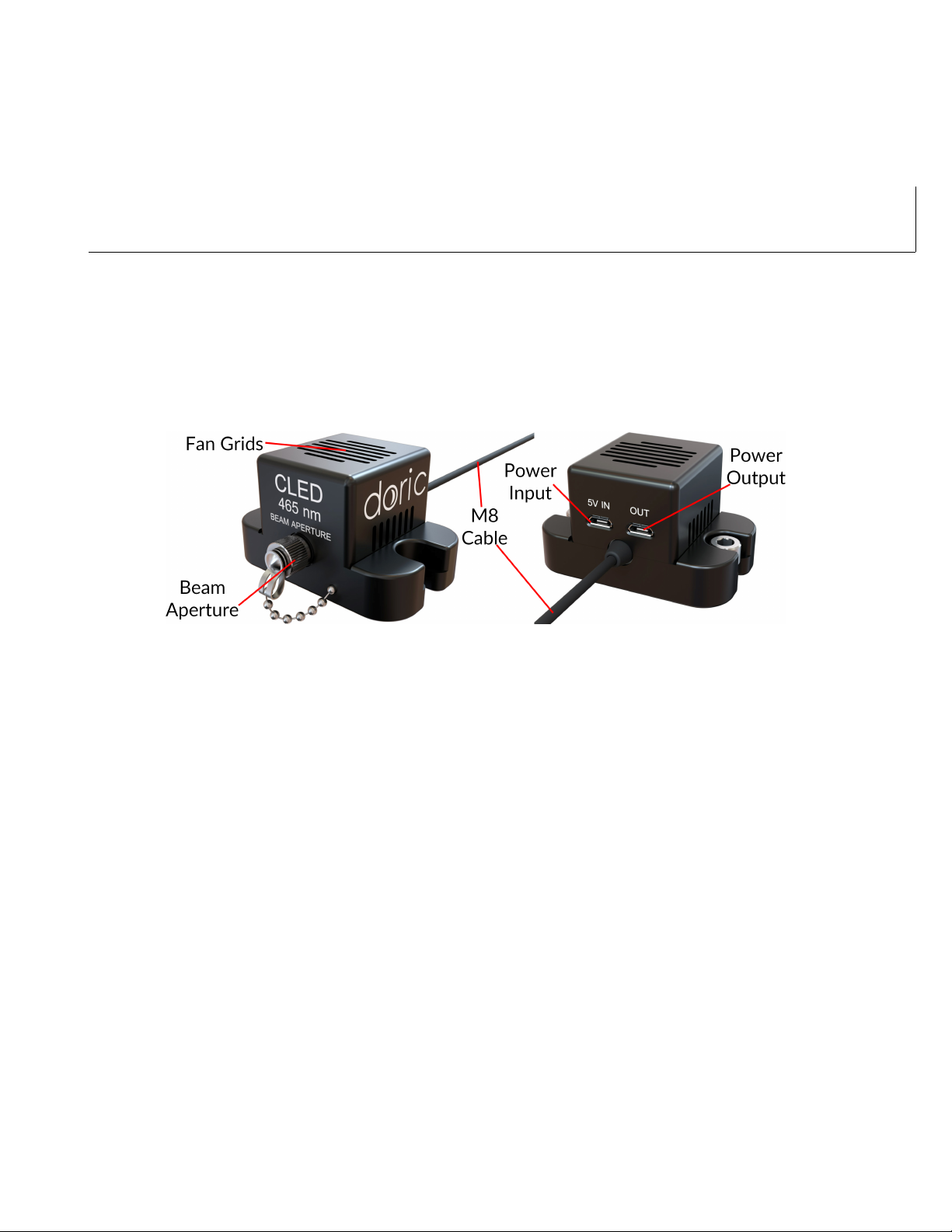
The LED driver is used to provide power and control of various LED modules. The Connectorized LED and Connectorized
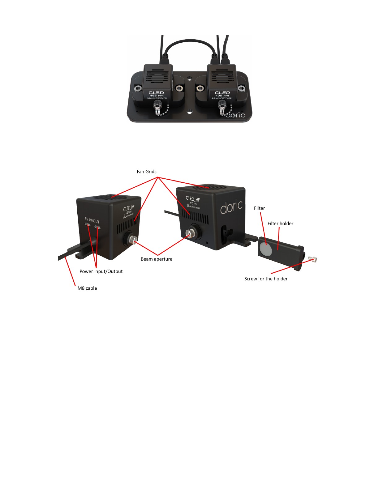
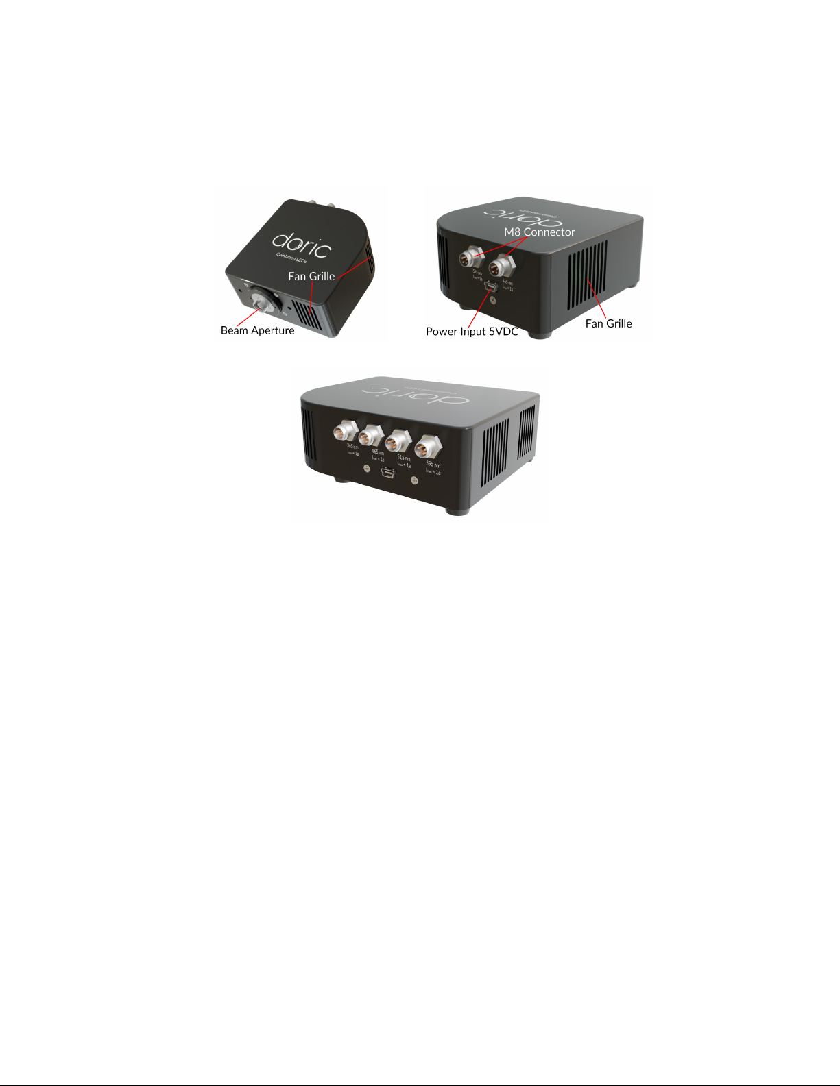
LED with Fiber-optic Rotary Joint can be used with the 1, 2 or 4-channel LED driver. The Combined LEDs and Combined
LEDs with fiber-optic rotary joints can be used with any driver having at least as many channels as the number of
combined LEDs.
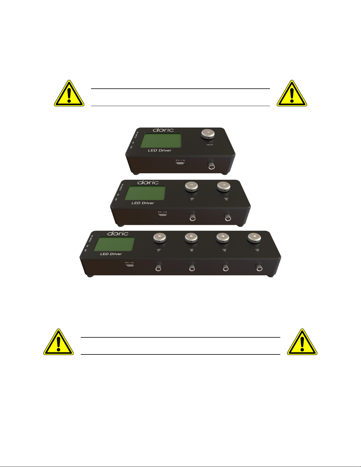
For safety precautions, the LED driver must be powered only by the
power supply provided with the product.
Figure 2.7: LED Drivers; 1-, 2- and 4-channel
Each LED Driver channel can be controlled manually or via the Doric Neuroscience Studio software. During stand-alone
operation, it is possible to change the operating mode (CW, external TTL, or external analog mode) and the current
sent to each LED. These changes can be done directly on the device with the Control Knobs and the LCD Display.
The driver is designed and is tested to be used only with Doric light sources.
For safety precautions, do not connect other devices in the M8 connectors.
Connecting the LED Driver to a computer provides the user with more options. Doric Neuroscience Studio software
allows the access to more operating modes like Continuous Wave, External TTL, External Analog, Square Sequence(s),
and Complex Sequence(s) modes. The Doric Neuroscience Studio enables the creation of different sequences of light
source activation. It also provides the possibility to let these sequences be triggered or paused by an external signal.
If more power is needed, it is possible to overdrive the LED Driver with the software for some LED with overdrive
capability.
•The LCD display (Fig. 2.8) allows easy operation and monitoring. For each channel, the LCD displays the type
of light source (LED), the operating mode, the center wavelength in nm and the current setting.
Chapter 2. Device Overview 10

Figure 2.8: Top view of a 4-channel LED Driver
•The Power key must be properly inserted into the key switch to enable operation of the light source(s) connected
to the driver. Note that, despite its similar shape, the power key is not a standard micro SD card such as those
used in some digital cameras. Do not attach the Key to a key fob or similar holder; this may prevent proper
insertion of the Power key.
•The M8 connector is used to link the driver and the LED.
•The Interlock Connector Plug (Fig. 2.9) allows the user to connect the driver to an interlock system. It is
recommended to connect the interlock plug to a laboratory interlock system. This is critical when using LEDs in
the UV or Infrared spectrum, as they are invisible to the naked eye.
Figure 2.9: Rear view of a 4-channel LED Driver
•The Input BNC allows the control of the LED driving current of the corresponding source with an analog or TTL
signal.
•The Output BNC are used to monitor the driving current of the corresponding light source.
•The 12 VDC power input connects the driver to its 12 VDC power supply.
•The USB-B Connector allows the driver to be connected to a computer using a USB-A/USB-B cable.
•The On/Off switch (Fig. 2.11) turns on/off the driver.
•The USB-A port (Fig. 2.10) is used, for some devices, to power the external light source module cooling fan.
There is no data transfer possible with this port.
Chapter 2. Device Overview 11

Figure 2.10: Front view of a 4-channel LED Driver
Figure 2.11: Side view of a 4-channel LED Driver
2.6 LED Fiber Light Source (LEDFLS)
The Doric LED Fiber Light Source integrates the LED Driver and the light source(s) into one convenient device that
reduces the number of optical connections and the system’s overall footprint. The Doric LED Fiber Light Source comes
in different packages from 1 to 4 channels, which can be used stand-alone or with a computer via USB connection.
The module has one or more beam apertures, each emitting a different wavelength (Fig. 2.12).
For safety precautions, the LED Fiber Light Source must be
powered only by the power supply provided with the product.
Each module contains the following elements:
•The Beam aperture (Fig. 2.13) is where the light exits the light source. The aperture is composed of a fiber
coupling assembly that injects the emitted light into an optical fiber. The standard model uses an FC fiber
connector. A safety FC metal cap is attached to the Beam aperture head to block the output light beam in
absence of optical fiber.
Chapter 2. Device Overview 12

Figure 2.12: LED Fiber Light Sources: 1-, 2- and 4-channels.
Figure 2.13: LED Fiber Light Source front
•The LCD display allows easy operation and monitoring. The LCD display shows the mode for each channel as
well as the constant or maximal current in mA.
•The Control knob is used to change the maximum current to the LED, as well as change the operation mode of
the system.
•The Safety key must be in place to enable module operation. Despite its similar shape, the safety key is not a
standard micro SD card such as those used in some digital cameras. Do not attach the Key to a key fob or similar
holder; this may prevent proper insertion of the Key Switch.
•The On/Off switch turns on and off the light source.
Figure 2.14: LED Fiber Light Source rear elements
Chapter 2. Device Overview 13

•The Interlock connector plug (Fig. 2.14) allows the user to connect the driver to an interlock system. It is
recommended to connect the interlock plug to a laboratory interlock system. This is critical when using LEDs in
the UV or Infrared spectrum, as they are invisible to the naked eye.
•The Input BNC allows external TTL or analog signals to control each individual light source.
•The Output BNC are used to monitor the current on each LED.
•The 12 VDC power input connects the module to its 12 VDC power supply.
•The USB-B connector allows the module to be connected to a computer using a USB-A/USB-B cable.
Chapter 2. Device Overview 14

3
Operation Guide
To reduce the risk of eye injury, it is sound practice to
NOT CONNECT/DISCONNECT OPTICAL FIBERS
when the light source is turned on
Notes:
•On all relevant devices, it is critical not to block or insert objects into the ventilation grids as this could block
airflow and reduce cooling efficiency.
•When not in use, place caps on the connectors for protection and cleanness.
3.1 Connectorized LEDs Setup
Figure 3.1: Connections of a Connectorized LED to a 1-channel LED Driver in stand-alone mode
15

1. Connect the LED Driver to the 12 VDC power supply.
2. Ensure the power key and the interlock (green) connectors are properly set in place.
3. Connect the Connectorized LED (CLED) to the driver. Align the M8 connector pins in the female receptacle on
the Doric LED driver, slide in and screw the nut in place.
4. Connect the CLED Fan Micro-USB 5V Input to the LED Driver 5V 1A Front USB Port with the provided USB
cable. A Micro-USB to Micro-USB cable can be used to power the fan of multiple LEDs by connecting the
Micro-USB output of a LED with the Micro-USB input of another LED.
5. For optimal performances, place the module in a well ventilated area. Overheating will affect LED power and
reduce its lifetime.
3.2 Combined LEDs Setup
1. Connect the LED Driver to the 12 V power supply.
2. Connect the Combined LEDs 5V DC Mini USB port to the LED Driver 5V front USB port using the mini-USB
cable.
3. Ensure the power key and the interlock (green) connectors are properly set in place.
4. Connect each channel of the LED driver to the corresponding input connectors of the Combined LEDs using M8
cables.
5. Switch ON the LED driver.
3.3 LED + Fiber-optic Rotary Joint Setup
1. Installation depends on the specific source chosen. If using:
•Single-LED model, the rotary joint must first be installed in its holder (Holder_FRJ_large,GH_FRJ). It can then
be mounted into the setup using 1/4 or M6 nuts and screws.
•Combined LED model, the holder is already integrated. It can then be mounted into the setup using 1/4 or
M6 nuts and screws.
2. Connect the Doric LED Driver to the 12 V power supply.
3. Connect the LEDFRJ 5V DC Mini USB port to the LED Driver 5V front USB port (for the 2, 3, and 4 channels
model) using the mini-USB cable.
4. Connect each channel of the LED driver to the corresponding input connectors of the LEDFRJ using M8 cables.
5. Ensure the power key and the interlock connector (green) are properly set in place.
6. Switch ON the LED driver.
Chapter 3. Operation Guide 16

Figure 3.2: LEDFRJ connection schema
3.4 LED Fiber Light Sources Setup
1. Connect the LED Fiber Light Source to the 12 VDC Power Supply.
2. For optimal performances, place the module in a well ventilated area, especially if used in continuous mode for
long period of time. Overheating will affect LED power and reduce its lifetime.
3. The LED Fiber Light Source is operated with the driver’s stand-alone capabilities (Section 3.6) or using the Doric
Neuroscience Studio software (Section 4).
Chapter 3. Operation Guide 17

3.5 FC Connector Installation
1. Clean the optical fiber connector before insertion. Use isopropanol and a lint-free wipe.
2. With an FC connector, the connector key must be oriented to enter within the receptacle slot to ensure proper
connection (Fig. 3.3).
Figure 3.3: FC connector, Fiber Installation
WARNING!
To reduce the risk of eye injury, it is sound practice to
NOT CONNECT/DISCONNECT OPTICAL FIBERS
when the light source is turned on
Chapter 3. Operation Guide 18

3.6 Stand-alone mode (without Doric Neuroscience Studio Software)
The following sections details stand-alone operation of the LED driver and the LED Fiber Light Source. For installation
of the light sources in stand-alone mode, see section 3.1 for Connectorized LED,3.2 for Combined LEDs,3.3 for LEDs
with fiber-optic rotary joint.
If either the LED driver and the LED Fiber Light Source are used as a stand-alone devices, 3 modes are available: Constant
current (CW), External TTL (Ext. TTL), and External Analog (Ext. Ana). The operating mode is changed by pressing the
Control knob (See Fig. 2.8 and Fig. 2.13). The maximal driving current is set by turning Control knob. Use a fast/slow
rotation for coarse/fine adjustment. The operating mode and the maximum driving current setting are independently
adjusted for each channel.
Constant current (CW)
Figure 3.4: Constant Current Mode Driver Signal
When using the CW mode, the user simply sets the driving current applied to the light source. The light source
is activated and an output beam will be visible as long as the driving current is above the minimum driving current
(Fig. 3.4).
External TTL (TTL)
Zero Voltage
Max Voltage
External Signal
Driver
Zero Current
Set Current
Enable Disable
Figure 3.5: Driver Signal Response to External Source in External TTL Mode
In the External TTL mode, the driver is activated by an input TTL signal coming from an external device. This activation
will follow the TTL pulse waveform. The driving current is set with the control knob, and is constant during each TTL
activation pulse.
Chapter 3. Operation Guide 19

External Analog (Ext. Ana.)
The External Analog mode is similar to the External TTL, except that the driving current is proportional to the voltage
applied to the BNC input connector (Fig. 3.6a). On the input BNC, a maximum voltage signal corresponds to a maximum
of 2000 mA current. Most LED light sources have a maximum current below this value which could result in a clipping
to the current output (see Fig. 3.6b).
To avoid this clip on the output waveform the maximum voltage setting must be equal to the maximal current
divided by 400 mA/V (the value of the relationship between current and input voltage) (Fig. 3.6a). For square modu-
lations, it is preferable to use External TTL mode instead of External Analog mode.
(a) Adjusted tension to maximum current
start stop
Min Voltage [V]
Ild,min [mA]
Ild,max [mA]
Max Voltage [V]
External
Device
Light Source
(b) Clipping of light source current output
Figure 3.6: External Analog output is proportional to the External Device voltage
Low power mode
To enable Low power mode, press the control knob for two seconds and a minus sign will appear indicating the switch
to the current divide mode. This option reduces the current, therefore the optical power. It is useful to get stable
signals in experiments requiring lower power (e.g. fiber photometry experiments). In this mode, the maximal current
is 200 mA (corresponding to a 5 V input) and the minimum is 2.5 mA. This allows a more stable LED power output at
lower electrical currents.
Chapter 3. Operation Guide 20
Table of contents
Other DORIC Lighting Equipment manuals
Popular Lighting Equipment manuals by other brands

STARVILLE
STARVILLE LED TRI FLOOD owner's manual

Jasco
Jasco PRO Series Setup

Inspire
Inspire Lakko Assembly, Use, Maintenance Manual

Feniex
Feniex FN-8118 instruction manual

Dialight
Dialight L-856 Quick start up guide

Federal Signal Corporation
Federal Signal Corporation Global Series Installation and maintenance instructions