DORIC Omnetics PZN-12 User manual

Fiber-optic & Electric Rotary Joint
User Manual
Version 1.0.1

Contents
1 Overview 3
1.1 Fiber-optic & Electrical Rotary Joint ......................................... 3
1.2 Holders and Accessories ................................................ 3
1.3 Rotary Joint Harwin 12/Omnetics PZN12 Adapter Kit .............................. 4
2 Operations Guide 5
2.1 Rotary Joint Holders .................................................. 5
2.2 Connectors ........................................................ 7
3 Specifications 9
4 Support 11
4.1 Maintenance ....................................................... 11
4.2 Warranty ......................................................... 11
4.3 Contact us ........................................................ 11
2

1
Overview
1.1 Fiber-optic & Electrical Rotary Joint
(a) Rotary Joint (b) Elements; Stator (Black) and Rotor (Yellow)
Figure 1.1: Fiber-optic & Electrical Rotary Joint
The Doric Fiber-optic & Electrical Rotary Joint (Fig.1.1a) is a low-torque hybrid rotary joint that allows transmits rota-
tion insensitive electrical and optical signals. It is composed of a Stator, which stays immobile, and a Rotor that moves
(Fig. 1.1b). This product is used with FC optical connectors and a choice of Male Harwin (6 or 12 contacts) or Female
HDMI (standard or Blackrock pinout) electrical connectors.
1.2 Holders and Accessories
The rotary joint comes standard with the Holder FRJ large (Fig. 1.2a). The gimbal mount GH FRJ (Fig. 1.2b) can be pur-
chased separately. A horizontal cable holder (Fig.1.2c) can be purchased to keep cables off-center and increase effective
torque applied to the rotor. The Fiber-optic & Electrical Rotary Joint is pre-installed with the adapter of the horizontal
cable holder.
(a) Large FRJ Holder (b) Gimbal Mount
Holder (c) Horizontal cable holder
Figure 1.2: Fiber-optic & Electrical Rotary Joint Holders
3

1.3 Rotary Joint Harwin 12/Omnetics PZN12 Adapter Kit
To integrate the rotary joint within electrophysiology systems that use Omnetics PZN-12 connectors, an adapter kit
can be provided. These elements allow a Harwin-connectorized rotary joint to serve as a rotary joint for Omnetics con-
nectorized systems. The adapter system is composed of the following elements.
Figure 1.3: Harwin-Omnetics Adapters and Parts
• The MIRROR Adapter is a cable with a Female Harwin 12-pin connector on one side and a Omnetics PZN12
connector on the other. To use, simply insert the Female Harwin connector in the Male Harwin connector on
the Stator side of the rotary joint. The pinout inside this adapter is mirrored to take into account the connector
mirroring in a Omnetics PZN12/Omnetics PZN12 cable.
• The STRAIGHT Adapter is a simple Female Harwin 12-pin connector/Omnetics PZN12 connector adapter. To
use, simply insert the Female Harwin connector in the Male Harwin connector on the Rotor side of the rotary
joint.
Figure 1.4: Adapters Connected to AHRJ (example), STRAIGHT on Rotor (yellow) and MIRROR on Stator (black)
Chapter 1. Overview 4

2
Operations Guide
2.1 Rotary Joint Holders
2.1.1 Holder FRJ large
The Holder FRJ large allows fixed usage of the rotary joint. Simply thread the rotary joint into the holder as shown in
Fig. 2.1. Ensure the stability of the joint in the thread to avoid slippage during use. The holder can then be secured in a
setup using 1/4 (or M6) screws and nuts.
(a) (b)
Figure 2.1: Holder FRJ large Installation
2.1.2 Gimbal Holder
The GH FRJ (Fig. 2.2) allows swivel movement of the rotary joint along 2 axes. The rotary joint is to be threaded into
the holder (Fig. 2.2) in the same way as with the standard holder. Ensure the stability of the joint in the thread to avoid
slippage during use. The holder can then be secured in a setup using 1/4 (or M6) screws and nuts.
Figure 2.2: HRJ in the GH FRJ
5

2.1.3 Horizontal Cable Holder
This holder is used to facilitate rotation by increasing the torque provided by the cable. When using the Horizontal Cable
Holder:
1. Slide the horizontal cable holder into the cable adapter, with its clamp facing down (Fig. 2.3a). The rod is held in
place using a 2-56 set-screw on the underside of the adapter.
2. Secure the clamp (facing down) onto the cable adapter rod using a #4-40 nylon set-screw.
3. Loop the electrical cable into the clamp, and secure it using a #4-40 nylon socket head cap screw (Fig. 2.3b). This
allows increased torque on the rotary joint when the clamp is displaced from the center of rotation.
(a) Horizontal Cable Holder Installation (b) Horizontal Cable Holder Cable Placement
(c) Fiber-optic & Electrical Rotary Joint Underside
Figure 2.3: Horizontal Cable Holder Standoff Placement
Chapter 2. Operations Guide 6

2.2 Connectors
The Fiber-optic & Electrical Rotary Joint has two different types of connectors, optical and electrical. There are two
connectors for each type, requiring a signal cable/patch cord (connecting to a console, computer or other signaling de-
vice) and a subject cable/patch cord (connecting to the experimental subject or device).
(a) Electrical Connectors (b) Optical Connectors
Figure 2.4: Rotary Joint Connectors
2.2.1 Electrical Cables
Ensure that the electrical connectors are free of dust using an air duster before installing the cables. When not in use,
install plastic caps on connectors for protection and cleanliness.
• Connect the signal electrical cable to the fixed electrical connector (Fig. 2.4a).
• Connect the subject electrical cable to the rotary connector (Fig. 2.4a).
• The subject electrical cable can be looped into the Clamp (Fig. 2.3b) to provide extra torque. The cable is secured
using a #4-40 nylon socket-head cap screw.
Chapter 2. Operations Guide 7

2.2.2 FC Connector Installation
1. Clean the optical fiber connector before insertion. Use isopropanol and a lint-free wipe.
2. With an FC connector, the connector key must be oriented to enter within the receptacle slot to ensure proper
connection (Fig. 2.5).
Figure 2.5: FC connector, Fiber Installation
To reduce the risk of eye injury, it is sound practice to NOT CONNECT/DISCONNECT OPTICAL
FIBERS when the light source is turned on.
Chapter 2. Operations Guide 8

3
Specifications
Table 3.1: Harwin Electrical Connector Configuration
Male (on rotary joint) Female (on adapter)
Table 3.2: HDMI Electrical Connector Configuration
Male (on cable) Female (on rotary joint)
Table 3.3: HDMI Electrical Connector Pinouts
HDMI Microscope HDMI Blackrock 2
9

Table 3.4: General Specifications
SPECIFICATIONS VALUE NOTES
Transmision 80% 200 µm core NA 0.22 Optical fiber
Maximum Variation 2% 200 µm core NA 0.22 Optical fiber
Wavelength Range 450-650 nm Others available on request
Start Up Torque 0.9 mN·m For 6 contacts, Typical Value
1.8 mN·m For 12 contacts, Typical Value
Input NA 0.22 -
Output NA 0.22 -
Fiber Type 200 µm core NA 0.22 -
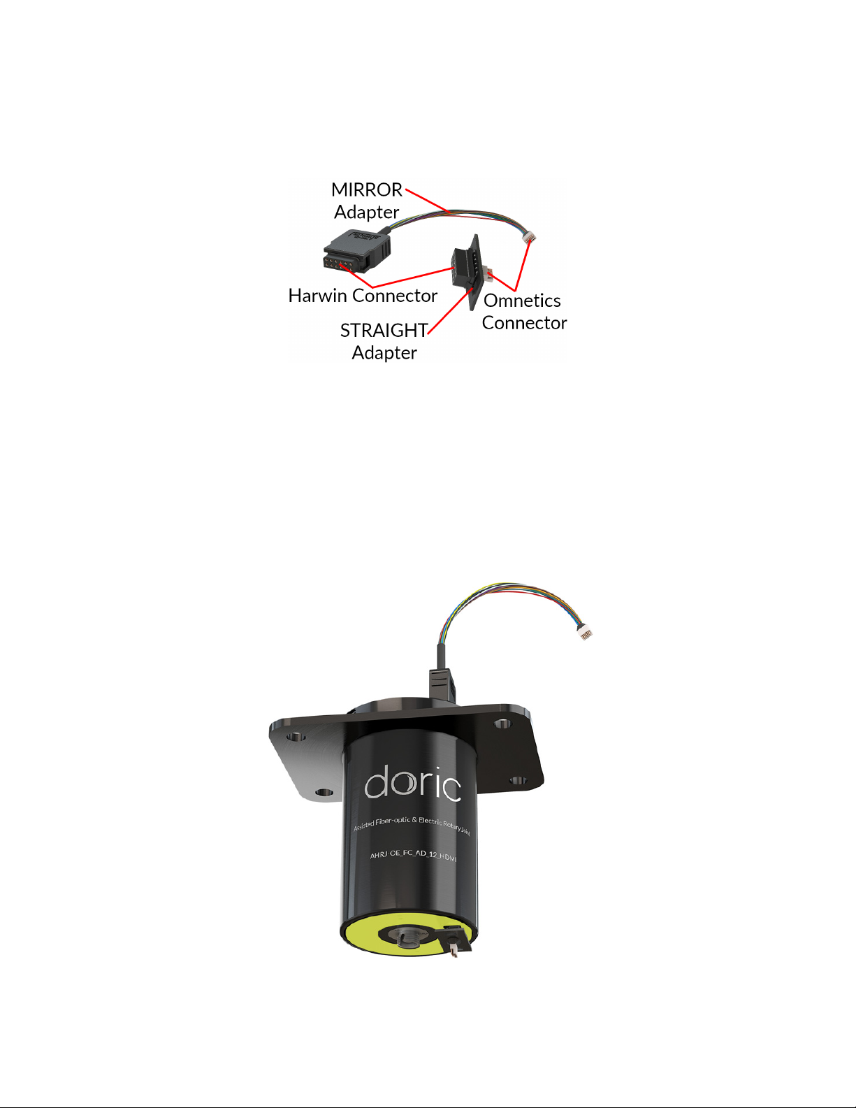
HDMI (Female) connector pinout type Microscope, Blackrock 2 -
Harwin (Male) connector type Datamate L-Tek serie 2 mm pitch, 12 contacts, 2 rows
Number of contacts 12 -
Contact Material Gold -
Maximum Current 2 A per contact -
Contact Resistance <500 mΩ-
Resistance Variation During Rotation (constant rotation) <100 mΩ5 VDC -
Rotation Speed up to 300 rpm -
Outer diameter 45.0 mm -
Length 59.4 mm -
Mass 123 g -
Table 3.5: Recommended Environmental Specifications
DESCRIPTION OPERATION STORAGE
Use Indoor Indoor
Temperature 0-40 ◦C 0-40 ◦C
Humidity 40-60% RH, non condensing 40-60% RH, non condensing
Chapter 3. Specifications 10

4
Support
4.1 Maintenance
The product does not require any maintenance. Do not open the enclosure. Contact Doric Lenses for return instructions
if the unit does not work properly and needs to be repaired.
4.2 Warranty
This product is under warranty for a period of 12 months. Contact Doric Lenses for return instructions. This warranty
will not be applicable if the unit is damaged or needs to be repaired as a result of improper use or operation outside the
conditions stated in this manual. For more information, see our Website.
4.3 Contact us
For any questions or comments, do not hesitate to contact us by:
Phone 1-418-877-5600
Email sales doriclenses.com
© 2019 DORIC LENSES INC
357 rue Franquet - Quebec, (Quebec)
G1P 4N7, Canada
Phone: 1-418-877-5600 - Fax: 1-418-877-1008
www.doriclenses.com
Chapter 4. Support 11
Table of contents
Other DORIC Lighting Equipment manuals
Popular Lighting Equipment manuals by other brands

Karma
Karma SMART FL60IP instruction manual

Flash
Flash Big Eye user manual

Iconasys
Iconasys LumiPad 360 LightBox Medium Setup instructions

EOS
EOS SBM-FL150 Installation and operation manual

ARLEE LIGHTING
ARLEE LIGHTING BELLA ARCHITECTURAL LINEAR Series Installation

Lightolier
Lightolier Calculite ProSpec PB3H3039 specification