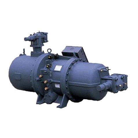
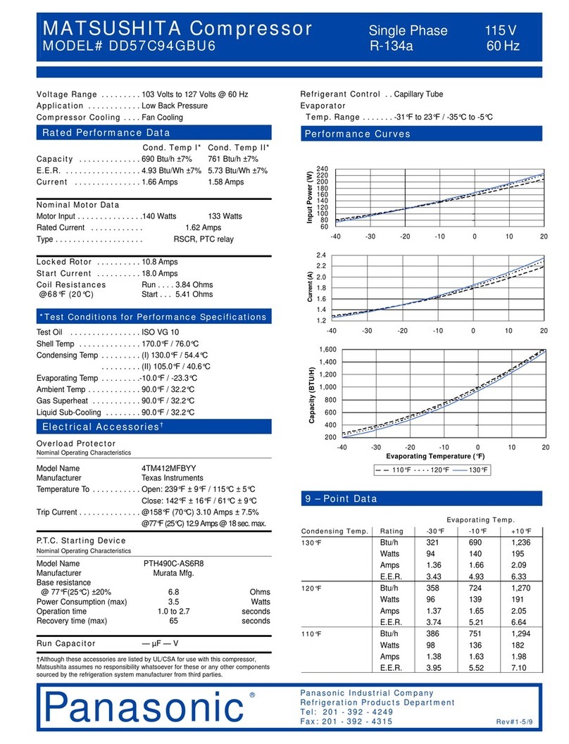
Dorin innovation H40CC User manual

ISTRUZIONI D’USO COMPRESSORI SEMIERMETICI
OPERATING INSTRUCTIONS SEMI-HERMETIC
COMPRESSORS
BEDIENUNGSANLEITUNG FÜR HALBHERMETISCHE
VERDICHTER

Istruzio i Operative / Operative I structio s / Bedie u gsa leitu g
1
SOMMARIO / SUMMARY / INHALTSVERZEICHNIS
Sicurezza / Safety / Sicherheit
• 2
Descrizio e ge erale / Overview / Übersicht
• 7
I stallazio e / I stallatio / I stallatio
• 9
Collegame ti elettrici / Electrical co ectio s / Elektrische A schlüsse
• 12
Messa i servizio / Commissio i g / I betrieb ahme
• 14
Accessori / Accessories / Zubehörteile
• 17
Ma ute zio e / Mai te a ce / Wartu g
• 19
Emerge ze / Emerge cy / Notfälle
• 20
Dismissio e / Disma tli g / Demo tage
• 21
Avverte ze / War i g / Hi weise
• 22
Prospetto a omalie / Failures chart / Fehlerliste
• 23
Figure / Figures / Abbildu ge
• 30

OFFICINE MARIO DORIN S.p.A.
2
Sicurezza
Safety
Sicherheit
INFORMAZIONI SUL PRESENTE
DOCUMENTO
Si raccoma da di leggere
atte tame te il co te uto di
queste istruzio i e co servarle
i prossimità del
compressore.
Si raccomanda inoltre di
mantenere una copia delle
presenti istruzioni presso gli
uffici tecnici dell’impresa
utilizzatrice.
Per qualsiasi intervento si
voglia effettuare sul
compressore, consultare
sempre il presente
documento, attenendosi
strettamente alle indicazioni
in esso contenute; per tutto
ciò non espressamente citato,
prima di intervenire,
contattare sempre il
costruttore.
Il costruttore decli a og i
respo sabilità per da i
causati a perso e o cose
dovuti alla ma cata
osserva za delle avverte ze
co te ute i questo ma uale.
Le Officine Mario Dorin. si
riservano il diritto di
aggiornare questa
pu licazione in qualunque
momento o apportare
modifiche a componenti
dell’unità se questo viene
ritenuto necessario per
esigenze costruttive o
commerciali.
E’ vietata la riproduzione
parziale o totale di queste
istruzioni senza l’autorizzazione
scritta delle Officine Mario
Dorin S.p.A.
Queste istruzioni non possono
contenere tutte le avvertenze
e precauzioni in grado di
coprire i rischi derivanti da
qualsiasi eventualità; deve
essere tenuto presente che
prudenza, attenzione, uon
senso, sono fattori che il
personale che effettua
l’installazione, la
INFORMATION ON THIS DOCUMENT
We recomme d to read
carefully the co te t of these
i structio s a d to keep them
ear the compressor.
We also recommend to keep
a copy of these instructions at
the technical divisions of the
user enterprise
For any intervention you want
to execute on the
compressor, look it up always
in this document strictly
following the indications it
provides; for anything which is
not expressly mentioned,
contact always the
manufacturer efore
intervening
The ma ufacturer refuses all
respo sability for the
damages caused to people
or to thi gs because of the
o -co formity with the
i structio s this ha dbook
provides.
Officine Mario Dorin S.p.A.
reserves the right to update
this pu lication at any time or
to change the components
of this unit if this is considered
as necessary for
manufacturing or
commercial needs.
The partial or total
reproduction of these
instructions is for idden
without the written
authorization y Officine
Mario Dorin S.p.A.
These instructions cannot
include all the instructions
and the precautions a le to
cover the risks resulting from
any event; you have to ear
in mind that caution, care
and common sense are
factors that the staff, who
executes the installation, the
BEZÜGLICH DIESER
A
NLEITUNG
Wir empfehle diese A leitu g
sorgfältig durchzulese u d sie
i der Nähe des Verdichters
aufzubewahre .
E enfalls empfehlen wir eine
Kopie der vorliegenden
Anleitung im technischen Büro
der anwendenden Firma
aufzu ewahren.
Bei jedem Eingriff den Sie am
Verdichter auszuführen
ea sichtigen, ziehen Sie stets
diese Anleitung zu Rate und
folgen Sie strikt den
angege enen Hinweisen; in all
jenen Fällen die hier nicht
ausdrücklich erwähnt sind,
wenden Sie sich vor jeglichem
Eingriff immer an den Hersteller.
Der Hersteller verweigert
jegliche Vera twortu g
bezüglich Schäde a
Me sche oder Gege stä de
die auf ei e Missachtu g der
Hi weise der vorliege de
A leitu g zurückzuführe si d.
Officine Mario Dorin S.p.A
ehält das Recht diese
Anleitung zu jedem elie igen
Zeitpunkt zu aktualisieren oder
Teile der Einheit zu verändern
falls dies aus autechnischen
oder kommerziellen Gründen
als erforderlich erachtet werden
sollte.
Es ist ver oten diese Anleitung
ganz oder teilweise ohne der
schriftlichen Genehmigung von
Officine Mario Dorin S.p.A. zu
reproduzieren.
Diese Anleitung kann nicht alle
Hinweise und
Vorsichtsmaßnahmen enthalten
um jegliche Art von Risiko zu
vermeiden; es ist zu eachten,
dass das für die Installation und
Wartung zuständige Personal in
der Lage sein muss
angemessene Vorsicht,
Aufmerksamkeit und gesunden
Istruzio i Operative / Operative I structio s / Bedie u gsa leitu g
3
manutenzione, e uso deve
possedere e sono elementi
che il costruttore può
trasmettere ma non
aggiungere.
CONFORMITÀ NORMATIVA
Il compressore a cui si riferisce
questo manuale di
installazione/manutenzione è
classificato come “quasi-
macchina” ai sensi della
Direttiva “Macchi e”
2006/42/CE e NON deve
essere messo in servizio finché
la macchina finale in cui
deve essere incorporato non
è stata dichiarata conforme,
se del caso, alle disposizioni
della stessa Direttiva
“Macchine” 2006/42/CE.
Il compressore è conforme
alla Direttiva “Bassa Te sio e”
2006/95/CE.
Il compressore è escluso
dall’applicazione della
Direttiva “Apparecchi a
pressio e” 97/23/CE (art. 1 §
3.10).
Il compressore è realizzato in
conformità alla norma EN
12693:2008.
L’installatore del compressore
all’interno dell’impianto
frigorifero è tenuto a
rispettare le pertinenti
disposizioni di legge del
paese di installazione in
riferimento agli impianti
elettrici ed agli impianti di
climatizzazione e le norme
della serie EN 378.
PERSONALE QUALIFICATO
Qualsiasi operazione di
installazione e/o
manutenzione di questi
compressori dovrà essere
eseguita solo da perso ale
qualificato ed in accordo alle
varie Normative nazionali
applica ili.
Questo manuale deve essere
letto attentamente prima di
eseguire ogni operazione sul
macchinario; l’osservanza
maintenance and the use
,
has to know; the
manufacturer can convey
these elements ut cannot
add them.
COMPLIANCE WITH THE
REGULATIONS
The compressor specified and
descri ed in this
installation/maintenance
manual is provided for
incorporation in machines as
defined in the Machi es
Directive 2006/42/EC; and
MUST NOT e put to use till
the final machine it has to e
incorporated to has not een
declared as compliant, if
need e, with the provisions
of the same Directive
“Machines” 2006/42/EC.
The compressor is in
compliance with the Low
Voltage Directive 2006/95/EC.
The compressor is excluded
from Pressure Equipme t
Directive 97/23/EC (art. 1 §
3.10).
The compressor is in
compliance with the
standard EN 12693:2008.
The installer of the
compressor inside the
refrigerant system, is o liged
to follow the relevant
provisions of the law in the
installation country, making
reference to the electrical
systems and to the air-
conditionning systems, as well
as the regulations of the EN
378 series.
QUALIFIED STAFF
Any installation and/or
maintenance operations of
these compressors shall e
carried out y qualified staff
only and according to the
several applica le national
regulations.
This manual shall e carefully
read efore carrying out any
operation on the machinery;
the o servance of the
Menschenverstand anwenden
zu können; diese Faktoren kann
der Hersteller zwar mitteilen
a er nicht mitliefern.
K
ONFORMITÄTSERKLÄRUNG
Der Verdichter der Gegenstand
der vorliegenden Installation-
und Wartungsanleitung ist, wird
laut der 2006/42/EG
Maschi e richtli ie als „Quasi-
Maschine“ ezeichnet und darf
NICHT in Betrie genommen
werden solange er nicht in die
Endmaschine einge aut wird
und diese, wenn notwendig
und immer gemäß der sel igen
Maschinenrichtlinie 2006/42/EG,
als konform erklärt worden ist.
Der Verdichter entspricht der
Niederspa u gsrichtli ie
2006/95/EG.
Der Verdichter o liegt nicht
den Anforderungen der
Regelu g bezüglich
„Druckgeräte“ 97/23/EG (Art. 1
§ 3.10).
Der Verdichter wurde
entsprechend der Norm DIN EN
12693:2008 ge aut.
Der Installateur ist verpflichtet
eim Ein au des Verdichters in
die Kühlanlage, die im
Installationsland geltenden
gesetzlichen Vorschriften in
ezug auf elektrische Anlagen,
Klimaanlagen und Vorschriften
der Serie DIN EN 378 zu
eachten
FACHPERSONAL
Jeglicher Installations- und/oder
Wartungseingriff an diesen
Verdichtern darf ausschließlich
von qualifiziertem Fachperso al
und entsprechend der
verschiedenen, nationalen
anwend aren Vorschriften,
durchgeführt werden.
Diese Anleitung muss vor jedem
Eingriff an der Maschine
sorgfältig durchgelesen
werden; die Beachtung der

OFFICINE MARIO DORIN S.p.A.
4
delle disposizioni è
condizione necessaria per la
sicurezza dell’operatore e dei
macchinari interessati.
DISPOSITIVI DI PROTEZIONE
INDIVIDUALE
Per qualsiasi intervento di
trasporto, installazione,
regolazione, manutenzione o
smantellamento del
compressore, il tecnico
addetto deve munirsi di
scarpe di sicurezza, guanti di
protezione ed occhiali di
protezione.
RISCHI RESIDUI
Il compressore è stato
progettato e realizzato
cercando di eliminare o
laddove impossi ile ridurre al
minimo i rischi per la sicurezza
e la salute degli utilizzatori.
Nonostante ciò, permangono
una serie di rischi residui per i
quali è indispensa ile che
l’utilizzatore adotti delle
misure di sicurezza
complementari a quelle già
realizzate tecnicamente sul
compressore.
PRESSIONE INTERNA
Prima di procedere alla
manutenzione del
compressore, rimuovere la
pressione all’interno del
compressore, agendo su
entram i i ru inetti.
Non rimuovere parti del
compressore soggette a
pressione interna prima di
aver effettuato tale
operazione.
PRECARICA DEL COMPRESSORE
All’interno dello sta ilimento
di produzione il compressore
è stato opportunamente
essiccato e caricato con gas
protettivo (aria secca – PR-70)
con sovrappressione di circa
0,5 ÷ 1 ar.
provisions is essential to the
operator as well as the
involved machinery safety.
DEVICES OF PERSONAL PROTECTION
For any transportation,
installation, adjustment,
maintenance or dismantling
of the compressor, the
authorized technician has to
supply himself with safety
shoes, protection gloves and
glasses.
OTHER RISKS
The compressor was
designed and manufactured
trying to avoid or, whenever it
is impossi le, to reduce to a
minimum the risks for the
users’ safety and health.
Nevertheless, there is still a
series of other risks and for
them it is a solutely
necessary for the user to
implement the safety
measures complementary to
those technically already
applied to the compressor.
INSIDE PRESSURE
Before starting the
maintenance of the
compressor, take away the
pressure inside y acting on
oth taps.
Do not remove those parts of
the compressor su ject to an
inside pressure efore having
executed this operation.
PRE
-
CHARGE OF THE COMPRESSOR
Inside the production factory,
the compressor has een
appropriately dried and
charged with protective gas
(dry air – PR-70) with an exta
pressure of a out 0,5 ÷ 1 ar.
Vorschriften stellt eine
notwendige Bedingung dar, um
die Sicherheit des Bedieners
und der etroffenen Maschinen
zu gewährleisten.
PERSÖNLICHE
S
ICHERHEITSVORKEHRUNGEN
Während des Transports, der
Installation, der Einstellung, der
Wartung oder der Demontage
des Verdichters muss der
zuständige Techniker
Sicherheitsschuhe,
Schutzhandschuhe und
Schutz rillen tragen.
VERBLEIBENDE
R
ISIKEN
Bei der Planung und Herstellung
des Kompressors wurde
versucht alle Sicherheits- und
Gesundheitsgefährdende
Risiken für den Bediener zu
vermeiden oder, wo dies
unmöglich war, diese auf ein
Minimum zu eschränken.
Trotzdem ver lei en einige
Restrisiken die es una ding ar
notwendig machen, dass der
Bediener zuzüglich zu den
Sicherheitsvorkehrungen die
technisch am Kompressor
ange racht sind, ergänzende
Schutzmaßnahmen anwendet.
I
NNENDRUCK
Vor jedem Wartungseingriff den
Druck im Kompressor durch die
zwei dazu vorgesehenen
Ventile a lassen.
Entfernen Sie keine Teile des
Verdichters die dem Innendruck
ausgesetzt sind, evor Sie nicht
den Druck a gelassen ha en.
S
CHUTZGASFÜLLUNG DES
V
ERDICHTERS
In der Produktionsstätte wurde
der Verdichter angemessen
getrocknet und mit Schutzgas
(Trockenluft – PR 70) mit einem
Ü erdruck von ungefähr 0,5 ÷ 1
ar gefüllt.
Vor der Installation des

Istruzio i Operative / Operative I structio s / Bedie u gsa leitu g
5
Prima di procedere
all’installazione del
compressore, scaricare la
pressione di precarica
agendo su entram i i
ru inetti. Non rimuovere alcun
componente dal
compressore prima di aver
effettuato questa operazione.
USTIONE DA CALDO
/
DA FREDDO
Attendere il raffreddamento /
riscaldamento delle superfici
esterne dopo lo spegnimento
del compressore per
intervenire sullo stesso, in
modo che non siano presenti
temperature pericolose.
Utilizzare guanti di protezione.
Installare il compressore in
luoghi non accessi ili a
personale non informato sui
rischi oppure impedirne
l’accesso con recinzione.
IRRITAZIONI CUTANEE
Attenzione: il compressore è
spedito con carica di olio.
Evitare il contatto diretto con
la pelle e con gli occhi, in
quanto irritante.
ASFISSIA
I refrigeranti HFC e HCFC non
sono tossici né nocivi, né
esplosivi, ma possono portare
ad asfissia nel caso di perdita
dell’impianto in am iente non
correttamente aerato.
I refrigeranti HFC e HCFC sono
inodore e incolore e possono
non essere percepiti
direttamente in caso di
emissione.
Rispettare le prescrizioni
sull’aerazione dell’am iente
di installazione.
RUMORE
Indossare dispositivi di
protezione dell’udito in caso
di permanenza prolungata in
prossimità del compressore in
funzione.
Before starting the installation
of the compressor, discharge
the pressure of pre-charge y
acting on oth service valves.
Do not remove any
component
from the
compressor efore having
executed this operation.
BURNS FOR HEAT
/
FOR COLD
Wait for the cooling/heating
of the external surfaces after
the compressor stopped if
you want to intervene on it; in
this way there are not
dangerous temperatures.
Make use of protection
gloves. Install the compressor
in places that are not
accessi le to the staff who
does not know a out the risks
or lock their access y
means of fences.
SKIN IRRITATIONS
Caution: the compressor is
shipped with a charge of oil.
Avoid the direct contact with
the skin and the eyes since it
is irritant.
ASPHYXIA
HFC and HCFC refrigerants
are not toxic or injurious or
explosive, ut can cause
asphyxia in case of system
leak into a not correctly well-
aired place.
HFC and HCFC refrigerants
are odourless and colourless
and can e not perceived
directly in case of emission.
Follow the instructions on
airing of the installation
place.
NOISE
Wear protection devices for
your hearing if you stay for a
long time near the working
compressor.
Verdichters, entladen Sie den
Druck der Schutzgasfüllung
ü er die eiden A sperrventile.
Entfernen Sie keine
Verdichterteile evor Sie nicht
den Druck a gelassen ha en
B
RAND
-/K
ÄLTEWUNDEN
Nach dem Ausschalten des
Verdichters muss man vor
jeglichem Eingriff das
A kühlen/sich erwärmen der
Außenflächen a warten um
gefährliche Temperaturen zu
vermeiden.
Schutzhandschuhe verwenden.
Installieren Sie den Verdichter in
Räumen zu denen kein Personal
Zugang hat, das nicht ü er
dessen Risiken informiert ist oder
untersagen Sie den Zugang
mittels einer Einzäunung.
H
AUTREIZUNGEN
Achtung: der Verdichter wird
mit einer Ölfüllung geliefert.
Vermeiden Sie den direkten
Kontakt mit Haut oder mit den
Augen da das Öl reizend ist.
E
RSTICKUNG
Die Kühlmittel HFC und HCFC
sind weder toxisch, noch giftig,
noch explosionsgefährdend,
können a er zu Erstickungstod
führen, falls die Anlage ein Leck
in einem schlecht elüfteten
Raum ha en sollte.
Die Kühlmittel HFC und HCFC
sind Geruch- und
Geschmacklos und können ei
Austritt nicht sofort
wahrgenommen werden.
Folgen Sie den Vorga en
ezüglich der Belüftung des
Installationsraumes.
L
ÄRMSCHUTZ
Tragen Sie eine
Lärmschutzvorrichtung falls Sie
sich länger in der Nähe des in
Betrie efindlichen Verdichters
aufhalten sollten.

OFFICINE MARIO DORIN S.p.A.
6
LESIONI DOVUTE AL TRASPORTO E
MOVIMENTAZIONE
Adottare le comuni misure di
sicurezza per il trasporto di
carichi pesanti mediante
attrezzature a forche o a
gancio.
Utilizzare unicamente il punto
di sollevamento indicato.
Indossare scarpe di sicurezza.
SEGNALETICA DI SICUREZZA
Sul compressore sono riportati
i seguenti sim oli grafici la cui
comprensione è importante
ai fini della consapevolezza
dei pericoli, degli o lighi e
dei divieti legati alla
macchina:
C
ORRENTE
E
LETTRICA
Esiste pericolo di folgorazione
qualora si venga a contatto
con i terminali elettrici. Il
coperchio della scatola
attacchi elettrici previene tale
contatto. Non alimentare
elettricamente il compressore
fino a che il coperchio della
scatola non sia
completamente chiuso e
integro.
S
UPERFICI
C
ALDE
/F
REDDE
Le superfici del compressore
possono avere temperature
tali da determinare ustioni da
caldo o da freddo.
P
UNTO DI
S
OLLEVAMENTO
:
É l’unico punto dove è
possi ile agganciare il
compressore per realizzarne il
sollevamento in sicurezza.
Non sollevare il compressore
da altri punti di ancoraggio.
RISCHIO ESPLOSIONE
Il compressore deve essere
protetto da u pressostato di
alta pressio e che fermi il
compressore i caso di
pressio e eccessiva:
INJURIES CAUSED BY
TRANSPORTATION AND HANDLING
Take the usual safety
measures for the
transportation of heavy loads
y means of forklift trucks or
hook equipments.
Use the indicated lifting point
only.
Wear safety shoes.
SAFETY INDICATIONS
It is important to understand
the following graphic signs in
order to e aware of the
dangers, the duties and the
prohi itions connected with
the machine:
E
LECTRICAL
C
URRENT
The danger of electrocution
exists when you are in
contact with the electrical
terminals. The lid of the ox
for the electrical connections
prevent this contact. Do not
feed electrically the
compressor till the lid of the
ox is not completely closed
and integral.
H
OT
/
COLD SURFACE
The temperatures of the
compressor surfaces are such
to cause urns for heat or for
cold.
L
IFTING
P
OINT
:
It is the only point where the
compressor can e hooked
so as to e lifted safely.
Do not lift the compressor
from other anchor points
RISK OF EXPLOSION
A high pressure ma ostat
has to protect the
compressor so that it stops
the compressor whe the
V
ERLETZUNGEN BEIM
T
RANSPORT ODER
BEI DER
B
EWEGUNG
Wenden Sie die ü lichen
Sicherheitsvorkehrungen an, die
eim Schwerlasttransport mittels
Ga elstapler oder
Transportgeräten mit Kranhaken
ange racht sind.
Die Maschine ausschließlich an
der angege enen Stelle
anhe en.
Tragen Sie Sicherheitsschuhe.
S
ICHERHEITSBESCHILDERUNG
Auf dem Kompressor efinden
sich die folgenden Schilder. Es
ist wichtig sie zu verstehen um
sich der Gefahren, der
Vorschriften und der
maschinen ezogenen Ver ote
ewusst zu sein:
S
TROMZUFUHR
Das Berühren der elektrischen
Anschlüsse kann zu einem
Stromschlag führen. Der Deckel
des elektrischen Schaltkastens
verhindert eine solche
Berührung. Schließen Sie den
Kompressor nicht am Strom an,
solange der Schaltkastendeckel
nicht vollständig geschlossen
und unversehrt ist.
KALTE
/
WARME
O
BERFLÄCHEN
Die O erflächentemperatur
des Verdichters kann zu Brand-
oder Kälteschäden führen.
H
EBESTELLE
:
Dies ist die einzige Stelle an der
der Kompressor sicher
hochgeho en werden kann.
He en Sie den Kompressor
nicht an anderen Stellen hoch.
E
XPLOSIONSGEFAHR
Ei Kompressor muss durch
ei e Hochdruck-
Druckwächter geschützt
werde um de Kompressor bei
überhöhtem Druck a zuhalte :

Istruzio i Operative / Operative I structio s / Bedie u gsa leitu g
7
-Il valore di taratura deve
essere i feriore al valore della
PS i dicata sulla targhetta del
compressore.
-Il pressostato deve
essere collegato alla presa di
pressio e situata sulla testa o
sulla camera di compressio e
del compressore (a mo te
del rubi etto di ma data).
pressure is extreme:
-The calibratio value
has to be lower tha the PS
value reported o the
compressor plate.
-The pressostat has to
be co ected to the
pressure tube located o the
head or o the compressio
chamber of the compressor
(upstream of the discharge
gas valve).
-Der Ei stellwert muss
u ter dem Druckwert liege
der auf dem Verdichter Schild
ei getrage ist.
-Der Druckwächter muss
a dem u absperrbare
Hochdrucka schluss des
Verdichters a geschlosse
werde , der sich am
Zyli derkopf oder auf der
Verdichtu gskammer des
Kompressors befi det
(oberhalb des
Druckabsperrve tiles).
Descrizio e ge erale
Overview
Übersicht
Il compressore è composto
da una carcassa che ospita
al suo interno il motore
elettrico e la parte
meccanica di compressione
a pistoni.
Il motore, opportunamente
collegato all’alimentazione di
energia elettrica, aziona il
manovellismo e i pistoni che
permettono, tramite
collegamento delle tu azioni
di aspirazione e di mandata,
la pressurizzazione del
refrigerante all’interno di un
impianto frigorifero.
USO PREVISTO DEL COMPRESSORE
Il compressore è stato
progettato e costruito
unicamente per la
compressione di refrigeranti
HFC (R404A / R507 / R134a /
R407C) e HCFC - CFC (solo
dove permesso dalle
legislazioni nazionali) nei
campi operativi descritti dai
diagrammi di applicazione
riportati in allegato (Fig. 4),
con il vincolo della
temperatura di mandata di
130°C e surriscaldamento in
aspirazione compreso tra 5K e
30K.
Il refrigerante utilizzato deve
avere un contenuto di
umidità inferiore a 10 ppm.
È vietato:
•l’utilizzo al di fuori del
campo operativo e dei
The compressor consists of a
framework hosting the
electric engine inside and the
mechanical part of the piston
compression
The engine, which is suita ly
connected to the power
supply, triggers the crank
gear and the pistons that
allow, y means of the
connection to the suction
and delivery pipes, the
pressurization of the
refrigerant
inside a refrigerant
system.
EXPECTED USE OF THE UNIT
This compressor has een
designed and manufactured
only for the compression of
the HFC (R404A / R507 /
R134a / R407C) and HCFC -
CFC refrigerants (when
national laws allow it only) in
the operational fields the
attached application charts
descri e (Fig. 4), with the
restrain of a delivery
temperature of 130°C and
overheating at the suction
etween 5K and 30K.
The employed refrigerant has
to have a humidity content of
10 ppm.
What follows is forbidde :
•The use outside the
operatio al field a d the
Der Verdichter esteht aus
einem Gehäuse in dessen
Inneren sich ein Elektromotor
und der mechanische Kol en-
Verdichtungsteil efinden.
Nach dem fachgerechten
Stromanschluss, setzt der Motor
das Kur elgetrie e und die
Kol en in Bewegung die durch
die Ver indung der An- und
A saugrohre, das Kühlmittel
innerhal der Kühlanlage unter
Druck setzen.
VORGESEHENE
A
NWENDUNG DES
K
OMPRESSORS
Dieser Verdichter wurde
ausschließlich zur Verdichtung
der folgenden Kühlmittel
entworfen und hergestellt: HFC
(R404A / R507 / R134a / R407C)
sowie HCFC – CFC (nur wo
durch nationalen Vorschriften
erlau t) zur Anwendung in
jenen Bereichen die in den
eiliegenden
Anwendungsschau ildern
eschrie en sind (A . 4), unter
Einhaltung der
Druckgastemperatur von 130°C
und einer Ü erhitzung ei der
Ansaugung die zwischen 5K
und 30K liegt.
Das Kühlmittel muss einen unter
10 ppm liegenden
Feuchtigkeitsgehalt ha en.
Es ist verbote :
•De Verdichter i a dere

OFFICINE MARIO DORIN S.p.A.
8
vi coli sopra i dicati;
•la compressio e di fluido
diverso da quelli i dicati
sopra;
•immergere il compressore
i modo totale o parziale
i fluidi o sottoporlo a getti
d’acqua viole ti;
•l’utilizzo i ambie ti a
rischio di esplosio e;
•l’utilizzo co temperature
ambie te i feriori a -20°C
o superiori a 60°C;
•l’utilizzo i ambie te
completame te chiuso
( o aerato);
•l’utilizzo i ambie ti co
prese za di age ti chimici
corrosivi.
Sulla targhetta di ciascun
compressore è riportato il tipo
e la quantità di olio caricato
in fa rica. Per eventuali
ra occhi e/o sostituzioni del
lu rificante utilizzare solo il
tipo indicato in targhetta.
IDENTIFICAZIONE DEL COMPRESSORE
Ogni compressore è
identificato attraverso un
numero di serie riportato su
targhetta metallica rivettata.
In accordo alla norma EN
12693, tale targhetta riporta:
•Nome del costruttore
•Modello del compressore
•Numero di serie
•Data di fa ricazione
•Max pressione di
funzionamento in mandata
(PS, in ar)
•Max pressione della zona
di assa pressione, sia in
funzionamento che a fermo
(Pss, in ar)
•Numero di fasi di
alimentazione elettrica
•Voltaggio nominale, in
above me tio ed
restrai s;
•The compressio of a fluid
other tha the above-
me tio ed o es;
•To plu ge totally or
partially the compressor
i to fluids or to subject it
to stro g jets of water;
•The use i to places at risk
of explosio ;
•The use at ambie t
temperatures lower tha
-20°C or higher tha 60°C;
•The use i to a completely
closed place ( ot well-
aired);
•The use i places where
corrosive chemical
age ts are prese t.
The plate of each compressor
reports type and quantity of
oil loaded at the factory.
For any possi le topping up
and/or replacement of the
lu e, use the type indicated
on the plate only.
COMPRESSOR IDENTIFICATION
Each compressor is identified
thanks to a serial num er
reproduced on the metal
plate riveted in compliance
with the EN 12693 regulation;
this plate specifies:
•Manufacturer’s name
•Compressor model
•Serial num er
•Manufacture date
•Max delivery running
pressure (PS, in ar)
•Max pressure of the low
pressure area oth in the
running and in the idle
condition (Pss, in ar)
•Num er of phases of
power supply
•Nominal voltage, in volts
•Nominal frequency, in Hz
Bereiche oder u ter
Missachtu g der obe
aufgeführte Bedi gu ge
ei zusetze ;
•ei a deres Kühlmittel zu
verwe de als die obe
a gegebe e ;
•de Verdichter ga z oder
teilweise i Flüssigkeite
ei zutauche oder starke
Wasserspritzer
auszusetze ;
•de Verdichter i
explosio sgefährdete
Räume zu betreibe
•der Betrieb bei
Raumtemperature die
u ter –20°C oder über 60°C
liege ;
•der Betrieb i vollstä dig
geschlosse e Räume
( icht belüftet);
•der Betrieb i Räume i
A wese heit vo
zersetze de chemische
Stoffe .
Auf dem Schild eines jeden
Verdichters ist die Art und die
Menge des Öles angege en
das werkseitig eingefüllt worden
ist. Bei einem etwaigen
Nachfüllen und/oder Ersetzen
des Schmieröls ausschließlich
die auf dem Schild
angege ene Sorte verwenden.
K
ENNZEICHNUNG DES
V
ERDICHTERS
Jeder Verdichter ist durch
eine Seriennummer
gekennzeichnet die auf
einem vernieteten
Metallschild eingetragen
ist. Gemäß Norm DIN EN
12693 stehen auf dem
Schild folgende
Anga en:
•den Herstellername
•das Verdichter Modell
•die Seriennummer
•das Herstellungsdatum
•Max. Betrie sdruck in
Ausgangsrichtung (PS, in Bar)
•Max Druck im
Niederdruck ereich, sei es ei
Betrie wie ei Stillstand (Pss. in

Istruzio i Operative / Operative I structio s / Bedie u gsa leitu g
9
Volt
•Frequenza nominale, in Hz
•Corrente a rotore
loccato, in Ampère
•Max corrente di
funzionamento, in Ampère
•Classe di protezione IP
•Velocità di rotazione
nominale, in RPM
•Volume spostato, in m
3
/h
!
A
VVERTENZA
:
I
L COMPRESSORE POTRÀ ESSERE
IMPIEGATO LIMITATAMENTE A
QUANTO RIPORTATO SULLA
TARGHETTA IN TERMINI DI
PS
(
MASSIMA PRESSIONE AMMISSIBILE
)
E
P
SS
(
MASSIMA PRESSIONE DI
STANDSTILL
)
COSÌ COME DEFINITE
DALLA
EN
12693.
Nelle comunicazioni con le
O.M.D. è importante fare
riferimento al numero di
matricola del compressore al
fine di consentire una corretta
e veloce rintraccia ilità del
prodotto.
•Current when the rotor is
locked, in Ampère.
•Max running current, in
Ampère.
•IP protection category.
•Nominal rotation speed in
RPM.
•Displaced volume in m
3
/h
!
W
ARNING
:
I
T SHALL BE POSSIBLE TO USE THE
COMPRESSOR WITHIN SYSTEM
PRESSURES IN ACCORDANCE TO
WHAT STATED ON ITS NAMEPLATE IN
TERMS OF
PS
(
MAXIMUM ALLOWABLE
PRESSURE
)
AND
P
SS
(
MAXIMUM
STANDSTILL PRESSURE
)
AS DEFINED IN
EN12693.
For communications with
O.M.D. it is important to
make reference to the
registration num er of the
compressor in order to allow
a correct and quick
tracea ility of the item.
Bar)
•Phasenanzahl der
elektrischen Anspeisung
•Nominale
Spannungsanga e, in Volt
•Nominale Frequenz, in Hz
•Strom ei lockiertem
Rotor, in Ampere
•Max Betrie sstrom, in
Ampere
•IP Schutzklasse
•Nominale
Rotationsgeschwindigkeit in
RPM (Umdrehungen pro
Minute)
•Theor. Hu volumen in m
3
/h
!
A
CHTUNG
:
D
ER
V
ERDICHTER DARF AUSSCHLIEßLICH
ZU DEN AUF DEM
S
CHILD ANGEGEBENEN
PS
W
ERTEN BETRIEBEN WERDEN
(
MAXIMAL ZUGELASSENER
BETRIEBSDRUCK
)
UND
P
SS
(
MAXIMAL
ZUGELASSENER
D
RUCK BEI
S
TILLSTAND
)
GEMÄß
DIN
EN12693.
Bei Mitteilung an Officine Mario
Dorin ist es wichtig, auf die
Seriennummer des Verdichters
hinzuweisen um das Produkt
richtig und schnell identifizieren
zu können.
I stallazio e
I stallatio
I stallatio
!
A
TTENZIONE
:
Qualora l’imballo risulti
da eggiato e/o sussista o
comu que dubbi sulla
i tegrità del compressore
ricevuto o procedere
all’i stallazio e dello stesso.
TRASPORTO DEL COMPRESSORE
Il trasporto del compressore
im allato su pallet o in cassa
deve avvenire sollevandolo
tramite un carrello elevatore
a forche, verificando
preventivamente la portata
dello stesso rispetto al peso
del compressore indicato in
figura 3.
Nel caso il compressore sia
privo di pallet o cassa, la
movimentazione deve
!
A
TTENTION
:
Should packagi g be
damaged a d/or doubts o
the i tegrity of the
compressor received arise do
ot proceed to the
compressor i stallatio .
COMPRESSOR TRANSPORT
The transport of the
packaged compressor on
pallets or into a case has to
e executed y lifting it y
means of a forklift truck, y
checking in advance the
capacity of it compared with
the weight of the compressor
indicated in figure 3.
Should the compressor e
without pallet or case, the
handling has to e executed
!
A
CHTUNG
:
Falls die Verpacku g
beschädigt ist u d/oder Zweifel
über die U versehrtheit des
gelieferte Verdichters
bestehe sollte , i stalliere Sie
das Gerät icht.
T
RANSPORT DES
V
ERDICHTERS
Der auf einer Palette und
Karton oder in einer Kiste
verpackte Verdichter muss mit
einem Hu - oder Ga elstapler
transportiert werden nachdem
die Ladefähigkeit des sel igen
mit dem Gewicht des
Kompressors verglichen wurde -
wie in A . 3 angege en.
Falls der Verdichter ohne
Palette oder Kiste sein sollte,
erfolgt der Transport durch den

OFFICINE MARIO DORIN S.p.A.
10
avvenire mediante il golfare
in dotazione (indicato in
figura 1 come lifting point) al
quale applicare il gancio di
sollevamento dell’attrezzatura
utilizzata, verificando
preventivamente la portata
dello stesso rispetto al peso
del compressore indicato in
figura 3.
Se è necessario utilizzare un
accessorio di sollevamento,
verificare che la portata dello
stesso sia pari o superiore al
peso del compressore
indicato in figura 3.
POSIZIONAMENTO
Il compressore può essere
posizionato in un locale
opportunamente areato
oppure all’esterno purché
en riparato dalle intemperie.
In entram i i casi la macchina
deve essere accessi ile solo
al personale autorizzato.
Installare il compressore
orizzontalmente sulle apposite
sospensioni antivi ranti
(vedere figura 2). Il
compressore può lavorare
anche con inclinazioni,
secondo l’asse longitudinale
e/o trasversale, diverse da
zero e dipendenti dal modello
di compressore (per
informazioni contattare il
nostro servizio di assistenza
tecnica).
AERAZIONE LOCALE INSTALLAZIONE
Per evitare concentrazioni
pericolose di refrigerante in
caso di fuoriuscita
accidentale, è necessario
disporre di adeguata
ventilazione nel locale
tecnico dove viene
posizionato il compressore. Il
locale di installazione deve
essere provvisto di areazione
naturale o ventilazione
meccanica, in accordo alle
norme tecniche applica ili.
Dal momento che eventuali
fughe di refrigerante
y means of the supplied
eye olt (which is indicated in
figure 1), the lifting hook of
the employed equipement
has to e coupled to, y
checking in advance its
capacity compared with the
weight indicated in figure 3
If it is necessary to use a lifting
accessory, check that its
capacity is equal to or higher
than the compressor weight
figure 3 shows.
COMPRESSOR ASSEMBLY
It is possi le to place the
compressor into a suita ly
well-aired room or outdoor
provided that it is well
sheltered from ad weather.
In oth cases the machine
has to e accessi le to the
authorized staff only.
Install the compressor in a
horizontal position on the
appropriate vi ration
dampers (see figure 2). The
compressor can work also
with inclination, in respect to
longitudinal and/or
transversal axis, different from
zero and dependent on
compressor model (for further
information please contact
our technical customer
service).
AIRING OF THE INSTALLATION ROOM
To avoid dangerous
concentrations of refrigerant in
case of casual leak, it is
necessary to provide a suita le
airing in the technical room
where the compressor is
located. The installation room
has to e equipped with
natural airing or mechanical
ventilation, in compliance with
the applica le technical
regulations
Since possi le refrigerant leaks
would tend to occupy the
in der Ausstattung enthaltenen
He ering (in A . 1 als Lifting
Point (He epunkt) ezeichnet).
In diesen He ering greift der
Kranhaken der angewandten
He evorrichtung ein nachdem
die Ladefähigkeit der sel igen
mit dem Gewicht des
Kompressors verglichen wurde -
sowie in A . 3 angege en.
Wenn notwendig verwenden
Sie He ezu ehör nachdem die
Ladefähigkeit des sel igen mit
dem Gewicht des Verdichters
verglichen wurde - wie in A .
3 angege en.
A
UFSTELLUNG
Der Verdichter kann in einem
angemessen elüfteten Raum
oder auch im Freien, jedoch
gut von Wetterun ilden
geschützt, aufgestellt werden.
in eiden Fällen muss dem
zugelassenen Personal der
Zugang frei stehen.
Den Verdichter auf den dazu
vorgesehenen
Schwingungsdämpfern
horizontal aufstellen (siehe A .
2). Der Verdichter kann, je nach
Modell, auch in anderen
Längs- und/oder Quer-
Schräglagen etrie en werden
(für eingehende Informationen
setzten Sie sich mit unserem
technischen Dienst in
Ver indung).
B
ELÜFTUNG DES
I
NSTALLATIONSRAUMES
Um gefährliche
Konzentrationen im Falle einer
unerwarteten Ausströmung von
Kühlmittel zu vermeiden, ist es
notwendig eine angemessene
Belüftung des
Maschinenraumes zu
gewährleisten in dem der
Verdichter aufgestellt ist. Der
Maschinenraum muss ü er eine
natürliche oder eine
mechanische Belüftung
verfügen; gemäß
anwend arer, technischer
Vorschriften.

Istruzio i Operative / Operative I structio s / Bedie u gsa leitu g
11
tendere ero a occupare la
parte inferiore dell’am iente
circostante si raccomanda di
porre l’aspirazione del sistema
di ricam io aria in posizione
ri assata
.
COLLEGAMENTO DELLE TUBAZIONI
Prima di procedere
all’installazione del
compressore, scaricare la
pressione di precarica
agendo su entram i i
ru inetti. Non rimuovere alcun
componente dal
compressore prima di aver
effettuato questa operazione.
Procedere all’i stallazio e
come segue:
- Rimuovere i rubi etti del
compressore;
- Saldare i rubi etti alle
tubazio i dell’impia to;
- Rimo tare i rubi etti sul
compressore;
- Eseguire la verifica delle
perdite dalle tubazio i
media te prova i pressio e
co N
2
o aria secca,
segue do tutte le procedure
di sicurezza ecessarie, come
ad esempio l’impiego di u
riduttore di pressio e
i terposto tra la bombola e
l’impia to e lascia do i
rubi etti del compressore
chiusi (ATTENZIONE! Dura te
questa prova o superare la
pressio e di sta dstill);
- Aprire i rubi etti del
compressore;
- Rimuovere l’aria
dall’impia to media te vuoto
fi o a mi imo 1,5 mbar;
- Procedere alla carica
del refrigera te ell’impia to.
! Atte zio e:
No usare il compressore per
fare il vuoto.
No alime tare
elettricame te il compressore
i co dizio i di vuoto!
lowest part of the surrounding
space we recommend to
place the suction of the air
exchange system in a lower
position
PIPES CONNECTION
Before starting the installation
of the compressor, discharge
the pressure of pre-charge y
acting on oth service valves.
Do not remove any
component from the
compressor efore having
executed this operation.
Execute the i stallatio i the
followi g way:
- Remove the service
valves of the compressor;
- Weld the service
valves to the system pipes;
- Reassemble the
service valves o the
compressor;
- Check the leaks from
the pipes by mea s of a
pressure test with N2 or dry
air followi g all the required
safety procedures such as,
for example, the use of a
pressure reducer placed
betwee the bottle a d the
system a d leavi g the
compressor service valves
closed (ATTENTION! Duri g
this test do ot overcome the
sta dstill pressure);
- Ope the service
valves of the compressor;
- Take away the air of
the system by mea s of the
vacuum till a mi imum of 1,5
mbar;
- Fill up the system with
refrigera t.
! Atte tio :
Do ot use the compressor to
create a vaccum
Do ot feed electrically the
compressor i vacuum
co ditio s!
Da etwaig ausströmendes
Kältemittel dazu neigt sich in
Bodennähe des umliegenden
Raumes auszu reiten, ist es
ratsam das Belüftungssystem in
tiefer Position einzu auen.
Rohra schluss
Vor der Installation des
Verdichters den Druck der
Schutzgasfüllung durch die zwei
A sperrventile a lassen. Vor
diesem Eingriff, keinen Teil vom
Verdichter entfernen.
Die I stallatio wie folgt
durchführe :
- Die Absperrve ile des
Verdichters e tfer e ;
- Die Absperrve tile a die
A lage rohre a löte ;
- Die Ve tile wieder auf
de Verdichter mo tiere ;
- Die Dichtheit der Rohre
durch ei e Druckprüfu g mit
N
2
oder Trocke luft
ko trolliere . Dabei si d alle
Sicherheitsvorschrifte zu
beachte wie z.B. Verwe du g
ei es Druckmi derers zwische
der Gasflasche u d der A lage
u d die Absperrve tile am
Verdichter geschlosse zu
halte (ACHTUNG!
Überschreite Sie bei dieser
Ko trolle icht de Stillsta d-
Druck);
- Öff e Sie die Verdichter
Absperrve tile;
- Sauge Sie durch
Vakuum die Luft aus der
A lage bis zu ei em Mi imum
vo 1,5 mbar ab;
- Fülle Sie das Kühlmittel
i die A lage.
! Achtu g:
Verwe de Sie de Verdichter
icht um das Vakuum zu
erzeuge .
Schließe Sie de Verdichter
icht a das Strom etz a we
er sich im Vakuum-Zusta d
befi det!

OFFICINE MARIO DORIN S.p.A.
12
! Atte zio e:
No utilizzare il compressore
per fare la carica di
refrigera te ell’impia to.
! Atte zio e:
Prima di collegare i rubi etti
alle tubazio i assicurarsi che
tutti i tappi i plastica sia o
stati rimossi.
Evitare per qua to possibile
l’i gresso di aria el
compressore! Te ere chiuse
le co essio i del
compressore dura te la
saldatura dei rubi etti alle
tubazio i.
Ma te ere chiusi i rubi etti,
u a volta rimo tati, fi ché
o si avvia la procedura di
messa i vuoto.
Assicurarsi che tutte le
tubazio i e le giu zio i sia o
perfettame te pulite e a
te uta.
Le indicazioni relative alle
connessioni standard sono
presenti nella figura 3.
!Atte tio :
Do ot use the compressor to
fill up the system with
refrigera t.
!Atte tio :
Before co ecti g the service
valves to the pipes be sure
that all the plastic caps have
bee take away.
Avoid, as much as possible,
the air i let i to the
compressor!
Keep the co ectio s closed
duri g the weldi g of the
service valves to the pipes.
O ce the service valves have
bee reassembled, keep
them closed till the vacuum
procedure is ot
impleme ted.
Make sure all the piping and
junctions are perfectly clean
and sealed.
The indications regarding
standard connections are
shown in figure 3.
! Achtu g:
Verwe de Sie de Verdichter
icht um die A lage mit
Kühlmittel zu fülle .
! Achtu g:
Bevor Sie die Absperrve tile a
die Rohre a schließe ,
überprüfe Sie, dass alle
Plastikstöpsel e tfer t worde
si d.
Verhi der Sie soweit wie
möglich de Luftei ga g i de
Kompressor! Halte Sie die
Verdichter Verbi du ge
währe d des A löte s der
Ve tile a die Rohre
geschlosse .
Halte Sie die Ve tile
geschlosse achdem Sie
diese wieder mo tiert habe
u d sola ge icht die
Evakuieru g ei geleitet worde
ist.
Überprüfe Sie, dass alle Rohre
u d Verbi du gsstelle perfekt
sauber u d dicht si d.
Anga en ezüglich der
Standardver indungen sind in
A . 3 geschildert.
Collegame ti
elettrici
Electrical
co ectio s
Elektrische A schlüsse
Il collegamento
all’alimentazione elettrica
deve avvenire aprendo la
scatola attacchi elettrici e
collegando le fasi di
alimentazione, il conduttore
equipotenziale ed i conduttori
per i segnali dei sensori di
temperatura secondo le
indicazioni riportate all’interno
del coperchio della scatola e
sulla targhetta del
compressore.
Collegare elettricamente la
resistenza carter, laddove
prevista, e le altre
apparecchiature elettriche.
La targhetta posta su ogni
compressore riporta i valori di
The connection to the power
supply has to e made y
opening the ox of the
electric connections and y
connecting the phases of
power supply, the
equipotential wire and the
wires for the signals of the
temperature sensors following
the instructions provided
inside the lid of the ox and
on the compressor plate.
Connect the carter
resistance, whenever it is
provided, and the other
electric equipments.
The plate positioned on each
compressor shows the
Der A schluss a das Strom etz
erfolgt durch Öff e des
elektrische Schaltkaste s u d
A schließe der
Stromzufuhrphase , der Erdu g
u d der Melder der
Temperaturse sore gemäß
de A gabe , die auf der
I e seite des Kaste deckels
u d auf dem Type schild
a gebracht si d.
Schließe Sie die a dere
elektrische Geräte u d die
Ölheizu g des Kurbelgehäuses
a , wo diese vorgesehe si d.
Das Type schild das auf jedem
Verdichter a gebracht ist, gibt
A gabe über die Spa u g
u d die Motorfreque z a :

Istruzio i Operative / Operative I structio s / Bedie u gsa leitu g
13
tensione e frequenza del
motore: assicurarsi che siano
in accordo con la tensione e
frequenza della linea.
! Atte zio e:
La pote za omi ale
i stallata i HP NON è u
parametro sig ificativo per il
dime sio ame to dei
compo e ti elettrici.
! Atte zio e:
Per il dimensionamento dei
contattori, dei cavi e dei
dispositivi di protezione
(fusi ili, interruttori
magnetotermici)
dell’impianto elettrico di
alimentazione riferirsi ai valori
di max corrente di
funzionamento (FLA) e di
corrente a rotore loccato
(LRA) riportate sulla targhetta,
sui cataloghi e sul software di
selezione.
! Atte zio e:
Prevedere sull’impianto
elettrico di alimentazione le
opportune misure di sicurezza
contro la protezione dai
contatti indiretti, in funzione
del sistema di distri uzione e
della resistenza di terra o
impedenza dell’anello di
guasto a terra (es. interruttore
differenziale ad alta
sensi ilità).
(Per gli schemi elettrici e le
indicazioni per il
collegamento vedi anche
pagina we www.dorin.com).
! Atte zio e:
Pericolo di cortocircuito
dovuto alla prese za di
co de sa ella scatola
attacchi elettrici.
Usare solta to passacavi
sta dard e prestare la
massima atte zio e
ell’effettuare u a
ermetizzazio e corretta
dura te il mo taggio.
motor’s voltage and
frequency values: make sure
they comply with the line’s
voltage and frequency.
! Atte tio :
The rated HP is NOT a
sig ifica t parameter for the
dime sio s of the electrical
compo e ts.
! Atte tio :
For the dimensions of the
contactors, ca les and
protection devices (fuses,
circuit reakers) of the
electrical power refer to the
values of maximum working
(FLA) and start-up current
(LRA) shown on the
nameplate as well as in the
catalogues and in the
selection software.
!Atte tio :
Take the suita le safety
measures for the electric
power supply against the
protection from indirect
contacts, depending on the
distri ution system and the
earth resistance or the
impedance of the earth fault
ring (i.e. high sensitivity
differential switch).
(For diagrams and
information for the electrical
connection see also the
page www.dorin.com).
! Atte tio :
Da ger of short circuit due to
the prese ce of co de sate
i the electrical co ectio s
box.
Exclusively use sta dard
fairleads a d be careful while
carryi g out the correct
airtight seali g duri g the
assembly.
überprüfe Sie dass die
Zuleitu ge dieser Spa u g
u d Freque z e tspreche .
! Achtu g:
Die i PS a gegebe e
Ne leistu g stellt KEINEN
wese tliche Parameter der
Dime sio ieru g der
elektrische Besta dteile dar.
! Achtu g:
Zur Dime sio ieru g der
Schütze, der Kabel u d der
Schutzvorkehru ge
(Schutzsicheru ge ,
mag etthermische Schalter)
der elektrische
Stromzufuhra lage, beachte
Sie die maximale
Betriebsstrom Werte (BSW) u d
die Betriebsstrom Werte bei
blockiertem Rotor (LRA) die auf
dem Type schild, i de
Kataloge u d i der Software
a gegebe si d.
!Achtu g:
Sehe Sie a gemesse e
Sicherheitsvorkehru ge gege
i direkte Ko takte auf der
A lage der Stromzufuhr vor;
beachte Sie dabei das
Verteilu gssystem u d de
Erdu gswidersta d oder die
Impeda z des Erdu gsri gs (z.B.
hochempfi dliche
Differe tialschalter).
(Für Schaltplä e u d A gabe
bezüglich der A schlüsse lese
Sie auch die Web-Seite
www.dori .com).
! Achtu g:
Ko de swasser im Schaltkaste
ka zu ei em Kurzschluss
führe .
Verwe de Sie ausschließlich
Sta dard Verschraubu ge u d
we de Sie die größte Sorgfalt
bei der richtige Abdichtu g
währe d der Mo tage a .

OFFICINE MARIO DORIN S.p.A.
14
! Atte zio e:
Nel caso di motori PWS fare
particolare atte zio e al fatto
che sia rispettata la seque za
delle fasi sui due avvolgime ti
altrime ti al mome to
dell’alime tazio e del
seco do avvolgime to si avrà
u a co dizio e di “rotore
bloccato” co pericolo di
gravi da i elettrici.
Il tempo di ritardo tra
l’alime tazio e dei due
avvolgime ti dovrà essere tra
0,2 e 0,5 seco di.
U i tervallo più lu go
porterebbe solo maggiori
rischi al motore.
Collegare il co duttore
equipote ziale di protezio e
al termi ale di terra.
S
ISTEMA DI PROTEZIONE
I motori vengono forniti con
protezione interna PTC o
tramite THERMIK; per quanto
riguarda i sensori PTC, i relativi
contatti (indicati con T1-T2
nello schema attacchi
elettrici) non devono essere
collegati alla tensione di
alimentazione ma alimentati
solo tramite il modulo
elettronico di protezione
motore disponi ile su richiesta
per i protettori tipo termistore;
viceversa per i protettori tipo
THERMIK non è necessario
l’impiego del modulo
elettronico e i contatti
andranno collegati in serie
con le altre protezioni
dell’impianto.
! Atte tio :
I the eve t of PWS motors
pay particular atte tio to the
observa ce of the seque ce
of the phases o the two
wi di gs, otherwise upo the
seco d wi di g feed, there
will be a co ditio of “rotor
blocked” with da ger of
serious electrical damages.
The delay time betwee the
two wi di gs feed shall be
i cluded betwee 0,2 a d 0,5
seco ds.
A lo ger ra ge would o ly
give rise to more risks for the
motor.
Co ect the protectio
equipote tial wire to the
earth termi al.
P
ROTECTION SYSTEM
The motors are equipped with
PTC internal protection or
through THERMIK; as for PTC
sensors, the relevant
connections (indicated as T1-
T2 in the wiring diagram) shall
not e connected to the
power supply voltage ut fed
only through the motor
protection electronic module
REL, availa le on demand for
protections such as
thermistor; vice versa for
protections such as thermik
the use of REL is not necessary
and the contacts shall e
connected in series with the
other system protections.
! Achtu g:
Falls PWS (Teilwicklu gsa lauf)
Motore verwe det werde ,
beachte Sie die richtige
Seque z der Phase auf de
zwei Wicklu ge weil so st
ach dem Stroma schluss der
zweite Wicklu g dies zu ei em
blockierte Zusta d des Rotors
führe würde mit schwere
elektrische Folgeschäde .
Die Verzögeru g der
Stroma speisu g zwische de
zwei Wicklu ge muss zwische
0,2 u d 0,5 Seku de betrage .
Ei e lä gere Zwische zeit
würde de Motor lediglich
größere Risike aussetze .
Verbi de Sie de
äquipote tiale Schutzleiter a
die Erdu g.
S
CHUTZSYSTEM
Die Motore werde mit ei em
i ter e PTC Schutz geliefert
oder si d durch THERMIK
geschützt. I Bezug auf die PTC
Se sore , dürfe die jeweilige
Ko takte (im Schema der
elektrische A schlüsse als T1-
T2 a gegebe ) icht a das
Strom etz a geschlosse u d
ur durch das elektro ische
Modul versorgt werde das auf
A frage für Schutzleitu ge der
Art Thermistor lieferbar ist:
umgekehrt ist es für THERMIK
Schutzleiter icht otwe dig
das elektro ische Modul
a zuwe de u d die
A schlüsse müsse i Serie zu
de a dere
Schutzvorrichtu ge der A lage
a geschlosse werde .
Messa i servizio
Commissio i g
I betrieb ahme
Lavori preparatori:
-Alimentare la resistenza
carter, se prevista (iniziare il
processo di ricarica del
refrigerante non al di sotto di
35°C÷40°C di temperatura
dell'olio).
Una volta raggiunte tali
Preliminary works:
-Feed the carter
resistance, if provided (start
the refrigerant recharge
process not elow
35°C÷40°C of the oil
temperature).
Once the indicated
Vorarbeite :
-Die Ölheizu g a schließe ,
we vorgesehe (mit dem
Fülle des Kühlmittels icht
begi e , sola ge das
Schmieröl icht 35°C÷40°C
erreicht).
Setzte Sie de Verdichter ach

Istruzio i Operative / Operative I structio s / Bedie u gsa leitu g
15
temperature, mettere in
marcia il compressore.
! Avverte za:
Prima di mettere i marcia il
compressore:
assicurarsi che il rubi etto di
aspirazio e e di ma data
sia o aperti;
No avviare il compressore
qua do al suo i ter o
sussisto o co dizio i di alto
vuoto. Il ma cato rispetto di
questa avverte za può avere
gravissime co segue ze
come il repe ti o aume to
della pressio e i ter a co
possibilità di esplosio e e
co segue ti rischi per il
perso ale che operi, tra siti o
stazio i i prossimità del
macchi ario.
Controllare il livello dell’olio,
verificando che sia compreso
fra i livelli chiaramente
indicati sulla spia visiva, come
nella, seguente figura:
I
NDICAZIONE LIVELLO OLIO
Dura te le prime ore di
fu zio ame to del
compressore, verificare il
livello dell’olio varie volte.
! Avverte za:
Nel caso sia ecessario
aggiu gere olio, utilizzare il
tipo i dicato i targhetta e
farlo gradualme te,
co trolla do il suo corretto
ritor o al compressore:
Pericolo di colpi di liquido!
! Avverte za:
Durante il funzionamento del
compressore occorre evitare
la migrazione di liquido
dall’evaporatore al
compressore.
Il funzionamento con
refrigerante liquido può
temperatures are reached,
start the compressor.
! War i g:
Before starti g the
compressor:
make sure the suctio
service valve a d the
discharge gas valve are
ope ;
Do ot start the
compressor whe high
vacuum co ditio s occur
i side it. No -observa ce of
this war i g ca have very
serious co seque ces such
as the sudde i crease of the
i ter al pressure with
possibility of explosio a d
co seque t risks for the staff
operati g, passi g by or
stayi g close to the machi e.
Check the oil level and verify
that the oil level is etween
the levels clearly indicated on
the oil sight glass, as shown in
the following figure:
OIL
LEVEL
INDICATION
Duri g the first hours of
operatio of the compressor,
check the oil level several
times.
! War i g:
If oil have to be added, use
the type i dicated o the
ameplate a d do it
gradually, checki g his
retur to compressor:
Da ger of liquid sluggi g!
! War i g:
During compressor
functioning, liquid migration
from evaporator to
compressor has to e avoid.
The functioning with liquid
refrigerant may cause
Erreiche dieser Temperature
i Betrieb.
! Achtu g:
Vor der I betrieb ahme des
Verdichters:
versicher Sie sich, dass
Saug-u d Druckabsperrve tile
offe si d;
Starte Sie de Verdichter
icht we sich i sei em
I ere ei Vakuum befi det.
Die Nichtbeachtu g dieses
Hi weises ka zu extrem
schwere Folge führe , z.B.
zum rasche A stieg des
I e drucks, Explosio sgefahr
u d achfolge de Risike für
das bedie e de Perso al oder
für das Perso al das sich i der
Nähe des Gerätes aufhält oder
dara vorbeigeht.
Ko trolliere Sie de Ölsta d
u d überprüfe Sie, dass er
zwische de Gre zwerte liegt
die klar auf der A zeige am
Ölschauglas zu sehe si d, so
wie i der achfolge de
Abbildu g:
Ö
LSTANDANZEIGE
Währe d der erste Stu de
ach der I betrieb ahme des
Kompressors überprüfe Sie
wiederholt de Ölsta d.
! Achtu g:
Falls Öl achgefüllt, werde
sollte, verwe de Sie de Typ
der auf dem Schild a gegebe
ist, fülle Sie stufe weise ach
u d ko trolliere Sie ob der
Rücklauf zum Verdichter richtig
erfolgt:
Risiko vo Flüssigkeitsschläge !
! Achtu g:
Ist der Verdichter i Betrieb,
muss die Verschiebu g vo
Flüssigkeit vom Verdampfer
zum Verdichter vermiede
werde .
Der Betrieb mit flüssige
Kühlmittel ka zu folge de

OFFICINE MARIO DORIN S.p.A.
16
provocare i seguenti
inconvenienti sulla macchina:
Olio con minor potere
lu rificante;
Rottura delle valvole e
conseguente
danneggiamento di altri
organi meccanici.
L’installatore deve verificare
che l’impianto presenti tutti gli
accorgimenti per evitare la
migrazione di liquido
dall’evaporatore al
compressore, in tutte le
condizioni di funzionamento.
Tale fenomeno può essere
identificato dalle seguenti
anomalie:
Formazione di ghiaccio o
rina sul ru inetto di
aspirazione e sulla linea
d’aspirazione;
Formazione di schiuma
eccessiva nel lu rificante
visi ile attraverso la spia
dell’olio;
Bassa temperatura nella
pancia del compressore.
SOSTITUZIONE DI COMPRESSORI
Una particolare attenzione va
posta quando si installa un
compressore al posto di un
altro; nell’impianto infatti
potre e esserci rimasta una
certa quantità d’olio tale da
causare “colpi di liquido” alla
partenza. Potre e essere
necessario rimuovere una
certa quantità di lu rificante
dal nuovo compressore.
Dopo l’avviamento del
compressore verificare che il
livello dell’olio si sta ilizzi fra i
livelli indicati al paragrafo
precedente.
! Avverte za:
Dura te il fu zio ame to
della macchi a co trollare
periodicame te che il livello
dell’olio sia compreso fra i
livelli chiarame te i dicati
sulla spia visiva.
following failures:
Oil with less lu ricant
power;
Broken of valves and
consequent damage of other
components.
The installer shall verify that
the plant has all the solution
to avoid the liquid migration
from evaporator to
compressor, in all possi le
operating conditions.
This phenomenon may e
identified y the following
functioning failures:
Ice or frost formation on
the suction service valves
and on suction line;
Excessive foam formation
on lu ricant, visi le through
warning light;
Low temperature of
surface of oil sump.
COMPRESSORS
’
REPLACEMENT
A particular attention shall e
paid in case a compressor is
replaced with another one;
as a matter of fact in the
plant a certain oil quantity
could have een left such as
to cause “liquid slugging” at
the start. It could e
necessary to remove a
certain lu e quantity from the
new compressor.
After the compressor starting
check that the oil level is
sta ilised etween the levels
indicated in previous
paragraph.
! War i g:
Duri g operatio of the
machi e periodically check
that the oil level is betwee
the levels clearly marked o
the sight glass.
Verdichterstöru ge führe :
we iger schmierfähiges Öl;
Ve tilbruch u d
achfolge der Bruch a derer
mecha ische Teile.
Der I stallateur muss
sicherstelle , dass die A lage
derart a gelegt ist, dass ei e
Flüssigkeitsverschiebu g vom
Verdampfer zum Verdichter i
jedem Auge blick des
Betriebes vermiede wird.
Folge de A omalie weise
darauf hi :
Eis- oder Frostbildu g auf
dem Saugabsperrve til u d
e tla g der A saugleitu g;
Durch das Ölschauglas
sichtbare starke
Schaumbildu g im Öl ;
Niedrige Temperatur im
Ölsumpf.
A
USTAUSCH DES
V
ERDICHTERS
Beso dere Sorgfalt ist beim
Austausch ei es Verdichters
aufzuwe de ; i der A lage
kö te ei e gewisse Me ge a
Öl verbliebe sei die
„Flüssigkeitsschläge“ bei der
I betrieb ahme verursache
kö te. Es kö te otwe dig
sei ei e gewisse Me ge a Öl
aus dem eue Verdichter zu
e tfer e .
Nach dem Start des Verdichters
ko trolliere Sie, dass sich der
Ölsta d zwische de
Gre zwerte die im vorige
Absatz a gegebe worde
si d, stabilisiert.
! Achtu g:
Ist die Maschi e im Ga g,
ko trolliere Sie regelmäßig
dass sich der Ölsta d zwische
de zwei klar a gegebe e
Gre zwerte des Ölschauglases
befi det.
Es kö te ützlich sei
regelmäßige Öla alyse

Istruzio i Operative / Operative I structio s / Bedie u gsa leitu g
17
Potre e essere utile
prevedere delle analisi
periodiche dell’olio per
verificare l’assenza di umidità
e/o di acidità.
Numero di partenze
Non avviare il compressore
più di 8 volte l’ora. Far
funzionare la macchina per
almeno 4 minuti ad
avviamento.
In ogni caso assicurarsi che i
ripetuti avviamenti non
pregiudichino il corretto livello
dell’olio nel carter.
It could e useful to provide
with regular oil analysis in
order to check the lack of
humidity and/or acidity.
Num er of starts
Do not start the compressor
more than 8 times per hour.
Let the machine run for at
least 4 minutes for each
starting.
However, e sure that
numerous startings do not
undermine the right oil level
into the case
durchzuführe um die
A wese heit vo Feuchtigkeit
u d/oder Säure achzuweise .
A zahl der Starta läufe
De Kompressor icht mehr als
8 Mal pro Stu de starte . Die
Maschi e pro Start mi deste s
4 Mi ute laufe lasse .
Jede falls sicherstelle , dass
die wiederholte Starts icht
de Ölsta d des
Kurbelgehäuses
beei trächtige .
Accessori
Accessories
Zubehörteile
I compressori possono essere
corredati di alcuni accessori
quali:
RESISTENZA CARTER
E’ uona regola applicare il
riscaldatore dell’olio nel
carter, perché esiste la
possi ilità che il fluido
frigorigeno si accumuli nel
carter stesso, a seguito di un
fermo impianto. Il riscaldatore
riduce la diluizione del
refrigerante liquido nell’olio.
Un foro è già previsto nel
carter dal lato del livello olio
per applicare la resistenza
(vedere istruzioni di
montaggio in figura 5).
Le resistenze standard sono
da:
100 o 200 W a seconda
della taglia del compressore;
tensione 230 V.
Su richiesta si possono fornire
resistenze per tensioni diverse
o di potenze diverse; si veda
la pagina we
www.dorin.com.
! Avverte za:
Prima di alime tare la
resiste za carter assicurarsi
che la te sio e sia quella
corretta e che la resiste za
sia i serita e bloccata
Compressors can e
equipped with some
accessories such as:
CRANKCASE HEATER
It is recommended to fit an oil
heater in the compressor
crankcase, ecause, If the
compressor is stopped, there
is the possi le storage of
refrigerant inside the
crankcase. The heater
reduce the dilution of liquid
refrigerant with the oil.
On the oil level side, the
compressor crankcase is
already equipped with a hole
where the resistance may e
applied (see mounting
instructions in figure 5).
The standard resistances are:
100 or 200 W on the asis of
compressor size;
Voltage 230 V.
On demand the crankcase
heater can e provided for
different voltages or different
power; see the we page
www.dorin.com.
! War i g:
Before e ergizi g the
cra kcase heater make sure
the voltage is correct a d
that the heater is i serted a d
locked i side its seat by
Die Kompressoren können mit
einigen Zu ehörteilen
ausgestattet sein, wie z.B.:
Ölheizu g
Es empfiehlt sich die Ölheizung
im Kur elgehäuse einzu auen
weil die Möglichkeit esteht
dass die Kühlflüssigkeit sich
nach einem Betrie sstopp im
Kur elgehäuse ansammelt. Die
Ölheizung verringert die
Verdünnung des Öles durch
flüssiges Kältemittel.
Es ist eine Bohrung im
Kur elgehäuse zum Ein au der
Ölheizung vorgesehen (siehe
Montageanleitung in A . 5).
Standard-Widerstände gi t es
zu:
100 oder 200 W je nach
Kompressor Größe;
230 V Spannung.
Auf Anfrage können
Ölheizungen für
unterschiedliche Spannungen
oder Leistungen geliefert
werden: siehe We -Seite
www.dorin.com.
! Achtu g:
Bevor die Ölheizu g
a geschlosse wird, überprüfe
Sie, dass die Stromspa u g
richtig ist, dass die Ölheizu g
sich i sei em Sitz befi det u d

OFFICINE MARIO DORIN S.p.A.
18
all’i ter o della sua sede
avvita do la boccola filettata
i dotazio e.
RAFFREDDAMENTO AUSILIARIO TESTA
I sistemi di raffreddamento
ausiliario sono due:
Ventilatore su testa;
Teste raffreddate ad
acqua.
Per maggiori dettagli vedere i
cataloghi compressori o il
ollettino tecnico (pagina
we www.dorin.com).
! Avverte za:
Verificare che il ve tilatore
ruoti el corretto se so di
rotazio e.
MODULO ELETTRONICO PROTEZIONE
MOTORE
Per poter utilizzare la
protezione a termistori del
motore è necessario
collegarla al modulo di
controllo elettronico (fornito di
serie insieme al compressore).
CONTROLLO PRESSIONE OLIO
Sui compressori dotati di
pompa dell’olio è installato di
serie (tranne che sulla
gamma H4 dove è un
accessorio) un pressostato
differenziale olio elettronico,
che misura la differenza di
pressione fra lato assa
pressione sul carter e la
pressione di mandata della
pompa.
Il pressostato differenziale
dell’olio può essere collegato
alla presa di assa pressione
presente sui carter di tutti i
compressori e alla presa di
pressione lato mandata sulla
pompa olio.
Il sensore DPS va inserito
nell’apposito alloggiamento
nella pompa olio.
Il valore di taratura del
pressostato è minimo 0,8 ar
(differenziale).
E’ previsto un ritardo di
risposta del pressostato di
almeno 90 secondi. Tale
ritardo permette la corretta
screwi g the bush supplied.
AUXILIARY COOLING HEAD
The most common auxiliary
cooling system are:
Body cooling fan;
Water cooled head.
For more details see the
catalogues on compressors
or the technical news letter
(we page www.dorin.com).
! War i g:
Make sure the fa is i the
right directio of rotatio
MOTOR PROTECTION ELECTRONIC
MODULE
In order to use the motor
thermistor protection it is
necessary to connect it to the
electronic module (supplied
as standard with the
compressor).
OIL PRESSURE CHECK
On the compressor equipped
with oil pump, it is installed as
standard (except on the
range H4 where is an option)
an oil differential pressure
switch, that measure pressure
difference from low pressure
side on the crankcase and
discharge pressure of the
pump.
The differential pressure
switch can e connected to
the low pressure connection
located on the carter of all
compressors and to the
pressure connection on the
discharge side of the oil
pump.
The oil differential pressure
sensor DPS must e
introduced in the apposite
lodging of the oil pump.
The setting value of switch is
at least 0,8 ar (differential).
It is set a delay time of the
switch at least of 90 seconds.
This delay allows the correct
oil pressurization at the
mit dem dazu vorgesehe e
Drehri g festgeschraubt ist.
Z
USÄTZLICHE
Z
YLINDERKOPFKÜHLUNG
Es sind zwei A kühlungssysteme
vorhanden:
Zylinderkopfventilator;
Wassergekühlte
Zylinderköpfe.
Für eingehende Details finden
Sie in den Verdichter Katalogen
oder in den technischen
Informationen (We -Seite
www.dorin.com).
! Achtu g:
Ko trolliere Sie die richtige
Drehrichtu g des Ve tilators
E
LEKTRONISCHES
M
ODUL ALS
M
OTORSCHUTZ
Um den Thermistorschutz des
Motors anwenden zu können
muss dieser an das
elektronische Kontrollmodul
angeschlossen werden (der
serienmäßig mit dem Verdichter
geliefert wird).
Ö
LDRUCKKONTROLLE
Bei Verdichtern die mit einer
Ölpumpe ausgestattet sind
(außer in der H4 Serie wo diese
als Zu ehör geliefert wird) wird
serienmäßig ein elektronischer,
Differential- Öldruckwächter
einge aut. Dieser misst den
Druckunterschied zwischen
Niedrigdruckseite des
Kur elgehäuses und
Hochdruckseite der Pumpe.
Der Differential-Öldruckwächter
kann an den
Niederdruckanschluss
angeschlossen werden, der sich
auf dem Kur elgehäuse aller
Kompressoren efindet sowie
an den Hochdruckanschluss der
Ölpumpe.
Der DPS-Sensor
(Differentialdruck-Sensor) muss
in die dazu vorgesehene
Bohrung in der Ölpumpe
montiert werden.
Der Einstellwert des
Druckwächters eträgt
mindestens 0,8 ar (differential).
Es ist eine Verzögerung des

Istruzio i Operative / Operative I structio s / Bedie u gsa leitu g
19
pressurizzazione dell’olio
all’avvio del compressore ed
evita improvvisi locchi
dell’impianto per revi
cadute di pressione.
compressor start up and
avoids compressor stops in
case of short pressure drop.
Druckwächters von mind. 90
Sekunden vorgesehen. Diese
Verzögerung ermöglicht die
Erreichung des richtigen
Öldruckes eim Anlaufen des
Verdichters und vermeidet eine
A schaltung des Verdichters
ei kurzanhaltendem
Öldrucka fall.
Ma ute zio e
Mai te a ce
Wartu g
PROCEDURA DI ISOLAMENTO DEL
COMPRESSORE
Prima di intervenire sul
compressore per attività di
manutenzione è necessario
sezionare lo stesso
dall’alimentazione elettrica.
Installare sulla linea di
alimentazione elettrica un
sezionatore lucchetta ile;
portarlo in posizione aperta
(0) e lucchettarlo durante
l’intervento di manutenzione.
A seguito dell’installazione,
nel caso di interventi che
richiedono lo smontaggio di
parti del compressore o per il
suo smantellamento, è
necessario procedere alla
depressurizzazione del
compressore secondo le
seguenti indicazioni:
•Sezionare l’alimentazione
elettrica come sopra
indicato;
•Chiudere la valvola di
intercettazione posta
sull’aspirazione del
compressore;
•Chiudere la valvola di
intercettazione posta sulla
mandata del compressore;
•Depressurizzare il
compressore (senza
disperdere il refrigerante
nell’am iente) fino a che la
pressione non è diventata
quella atmosferica.
Se si rende necessario
lavorare con la scatola
attacchi elettrici aperta e
sotto tensione, l’operazione
deve essere eseguita da
personale specificatamente
PROCEDURE FOR THE COMPRESSOR
INSULATION
Before carrying out any kind
of intervention on the
machine it is necessary to
interrupt the main power
supply of the system.
Install on the power supply
line a switch selector that can
e padlocked, place it in an
open condition (0) and
padlock it during the
maintenance.
After the installation, in case
of interventions requiring the
dismantling of parts of the
compressor or for its
dismantling, it is necessary to
start the compressor
depressurization according to
the following indications:
•Dissect the power
supply as it is a ove
specified;
•Close the on-off valve
placed on the suction of the
compressor;
•Close the on-off valve
placed on the delivery of the
compressor;
•Depressurize the
compressor (without
dispersing the refrigerant in
the room) till the pressure
does not correspond to the
atmospheric one.
In case it is necessary to work
with the live open electric
oard, such operation shall
e carried out y qualified
and expert staff.
In no case keep on
I
SOLIERUNGSPROZEDUR DES
V
ERDICHTERS
Vor jeglichem Wartungseingriff
am Verdichter, ist es notwendig
diesen von der Stromzufuhr
a zuschalten.
Bauen Sie in die Stromzufuhr
einen verriegel aren Schalter
ein; ringen Sie diesen in die
offene Stellung (0) und
lockieren Sie diese Stellung
während der Wartung.
Nach der Installation, oder ei
Eingriffen die eine Demontage
von Teilen des Kompressors
enötigen, oder weil der
Kompressor still gelegt werden
muss, ist es notwendig den
Druck im Kompressor wie folgt
zu verringern:
•Trennen Sie den
Stromkreis wie o en
eschrie en;
•Schließen Sie das
Sauga sperrventi das sich auf
der Saugseite des Verdichters
efindet;
• Schließen Sie das
Drucka sperrvenil das sich auf
der Druckseite des Kompressors
efindet;
•Lassen Sie den Druck des
Verdichters solange a (ohne
das Kühlmittel zu verlieren) is
der Luftdruck erreicht wird.
Wenn es notwendig wäre ei
offenem und angeschlossenem
Anschlusskasten zu ar eiten;
darf der Eingriff ausschließlich
von spezifisch qualifiziertem
Personal ausgeführt werden
This manual suits for next models
71
Table of contents
Other Dorin innovation Compressor manuals