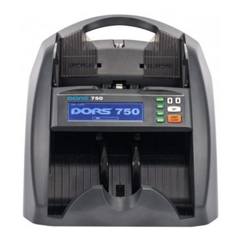
Dors 750 User manual

www. d o r s. co m
User Manual
Version .1 0
750
BANKNOTE COUNTER
USER MANUAL
© DORS LLC 2012

3
Introduction ......................................................................................................... 4
Specifications ....................................................................................................... 4
Safety Precautions!................................................................................................ 5
Delivery Set:.......................................................................................................... 6
Appearance.......................................................................................................... 6
Operating Keys..................................................................................................... 7
Operation............................................................................................................. 11
Menu Setup .......................................................................................................... 13
Error Messages...................................................................................................... 16
Troubleshooting ................................................................................................... 19
Counter Maintenance ........................................................................................... 19
Transportation And Storage. ................................................................................. 19
Support And Warranty .......................................................................................... 20
Warranty Conditions ............................................................................................. 21
Authorized Service Centers:................................................................................... 22
BANKNOTE COUNTER DORS 750BANKNOTE COUNTER DORS 750
CONTENTS

Specifications
4 5
READ THIS MANUAL CAREFULLY
BEFORE OPERATION START!
Dear Customer, we would like to thank you for selection of the
DORS 750 – the banknote counter able to determine
authentication of banknotes and their denomination.
The banknote counter (hereafter counter) is developDORS 750
by , Moscow Russia, and manufactured byKB DORS LLC DORS
Industries (China) Ltd, Shilong Business Center, Shilong Information
Industrial Park, Building 17, the city of Guangdong, the province of
Guangdong, China.
The counter is intended for counting and batching of US dollars,
Euro and other world currencies together with recognition of their
authenticity, denominations and amount. Authentication is made by
comparing the
data obtained during the banknote detection in the ultraviolet, infrared
and visible ranges with the reference data stored in the counter
memory.
INTRODUCTION
Hopper capacity, not more than.............................500 banknotes;
Stacker capacity, not more than............................. 150 banknotes;
Banknote counting speed (+ 15%)............ ........ 600/1000/1500 banknotes per minute;/– .
Banknote size............................. 117—1 0 mm (width),........................... 8
85 —90 mm (length),
0,05—0,2 mm (thickness);
Batch select...........................................................1—999;
Banknotes feed system..........................................Roller system of a friction type;
Counting sensor.................................................... Line of sensitive optical components of the
infrared and visible ranges, a built-in
system of the banknote pattern
recognition.
Verification in an ultraviolet light and a two-
track checking of the paper fluorescence
level;
Display ................................................................. STN, graphical, 256x64 pixels;
Power supply ........................................................ 100-240 VAC, 50/60 Hz;
Consumption current, not more than .....................0.5-0.25 A;
Operating temperature range................................ +10°C to +35°C;
Air relative humidity at + 25°C ............. to................... 40% 80%;
Atmospheric pressure ........................................... 84 to 107 KPa (630 to 800 mm Hg).
Overall dimensions (not more than):
Height.................................................................. 270 mm
Width................................................................... 290 mm
Depth................................................................... 240 mm
Net weight, not more than....................................4.2 kg
Gross weight, not more than.................................5.4 kg
Lifetime*.............................................................. 7 years
– The establishes an official seven-year (7 years) lifetime period for the* DORS
counter provided all the service regulations are observed. Taking into account high quality of
the , its reliability and safety degree, real lifetime of the counter may significantlyDORS 750
exceed an official one.
SAFETY PRECAUTIONS!
To ensure long life and reliable operation of the counter, its user
shall meet the following operation requirements and observe the
belowmentioned safety precautions:
1. The counter rotating parts are potentially hazardous for the user.
Therefore, we highly recommend that the user should avoid any
jewelry and loose clothes as well as pin their long hair when operating
the counter;
Avoid getting of any metal object or liquid into the counter;2.
To connect the counter to the power network, use a receptacle3.
with a protective earth contact ( ).PE
Location of the receptacle shall provide the user with a direct access
to the receptacle;
Unplug the counter after work has been completed.4.
If the counter is out of use for a long time, its power switch shall5.
be in the « » position;O
The device shall be installed on an even horizontal surface;6.
Do not use the counter at an extremely low or high temperature,7.
and avoid humidity as well as its exposition to the direct sunlight;
Do not touch the inside parts of the counter if it is connected to8.
the power network;
When dealing with the counter installation, mind a negative9.
impact provided by a high level of dust content on the counter
operation quality;
To avoid any fire or short circuit, do not install the device in10.
places where it may be at risk of a soot or steam impact.
BANKNOTE COUNTER DORS 750BANKNOTE COUNTER DORS 750

67
Delivery Set:
Banknote counter DORS 750 ...................................................... 1pc.
Power cord..................................................................................1pc.
User manual ...............................................................................1 pc.
Package ..................................................................................... 1 set
COUNTER DESCRIPTION
Appearance
Figure 1
7
8
9
10
11
Screw to adjust thickness of the
banknotes being counted;
Banknote guides;
Hopper;
Control panel;
Stacker;
Stacker wheels;
Remote display connector;
USB connector for making a personal
computer connection;
Power switch;
Fuse;
Power connector.
Appearance
Figure 2 Control panel
1
2
3
4
6
5
CONTROL PANEL
1. Graphical display;
2. MODE key for switching the counting modes;
3. MAN ON OFFkey for switching / of the manual start;
4. ADD ON OFFkey for switching / of the summation mode;
5. BATCH key for switching on a variable batching mode;
6. UPNavigation key ;
7. DOWNNavigation key ;
8. SET key for the menu entry /selection confirmation;
9. START CLEAR/ key for the start of counting in the mode of manual start / clearing the
results.
1
3
4
5
7
2
9
8
6
OPERATING KEYS
2. The MODE key for the banknote counting mode selection
The counter may count banknotes in three modes:
COUNT DENOMINATION MIX, , . To select a mode, use a
sequential search by pressing the key. The selected mode isMODE
shown in the left part of the graphical display table. The mode types:
– The mode for simple counting. This mode allows1. COUNT
counting of banknotes; the number of the counted banknotes is
shown on the display.
Indicator of switching on
simple counting Number counted banknote
BANKNOTE COUNTER DORS 750BANKNOTE COUNTER DORS 750
1
4
3
2
5
6
7
8
9
10
11

89
2. – The mode for counting banknotes of theDENOMINATION
same denomination, together with determination of the sum. The
mode for counting banknote of the same denomination, together with
detection in the infrared – IR and visible ranges, determination of the
total sum of the counted banknotes and determination of the
banknotes belonging to the given denomination (denomination is
determined by the first banknote in the batch to be counted).
The indicator of switching on
counting, together with sum determination
The sum of the
counted banknotes
Currency
Banknote denomination
The number of the counted
banknotes
3. – The mode for counting a mix of banknotes with differentMIX
denomination but relating to the same currency, together with
detection in the IR and visible ranges and with determination of
– the total sum of the counted banknotes;
– the number of the banknotes and their sum by each
denomination.
Total number of the
counted banknote
Total sum of the
counted banknote
Indicator of switching on the
counting of the banknote mix
Move to a detailed view of
counting
Banknote
denomination
The number of the counted
banknotes by denomination
The sum of the counted banknote by
denomination
3 The MAN key to switch over a counting mode
(manual/automatic start)
1. The key sets the counter in a manual or an automaticMAN
startmode.
2. Press the key to activate the manual mode. The indicatorMAN
MANUAL on the graphical display (in the top left corner of the left part
of the table) appears at the manual start mode activation. To
startcounting, press the key on the control panel.START/CLEAR
The manual start activation
indicator
3. Press the key to switch off the manual mode.MAN AUTO
appears on the graphical display, in the top left corner of the left partof
the table. The function being activated, the counter startsAUTO
counting automatically as soon as a banknote gets into the hopper.
4 The ADD key (summation)
The Sum mode is used to sum the number of the banknotes being
counted by their denominations and determine their total sum.
Moreover, the newly-counted number will be added to the one counted
before.
Индикатор включения
автоматического старта
BANKNOTE COUNTER DORS 750BANKNOTE COUNTER DORS 750

10 11
Press the key to switch on the mode of summation. AADD
repeated pressing of the key switches this mode off. To clean the
results of summing, press the / key and hold it whileSTART CLEAR
the stacker and the hopper are empty.
5 The BATCH key for setting a batch size
You may set the required batch size from 1 to 999 banknotes.
When counting of the set banknote number is over, the device stops,
indicates the total number of the counted banknotes and gives an
audio signal (if the latter is switched on). If there is set the number
exceeding 100 banknotes, the counter stops after counting another
100 banknotes and resumes counting after the banknotes have been
removed from the stacker. This function is available only for the
COUNT DENOMINATIONand modes.
To set the required number of banknotes, use two methods:
1. Selection among the preset values –multiple pressing of the
BATCH key results in a circular search: 5-10-25-50-100 banknotes.
The summation mode
activation Indicator
Result of the accumulation the data on the banknote
counting by denominations Sum by denominations
Total sum of counting
Number of banknotes in batch, selected from
preset values
2. Holding of the key during 3 sec. results in a manualBATCH
setting of the required number. In this mode, use the navigation keys
and to set the required value for the edited digit (the
underlined one). To move to the next digit, use the key. To exitSET
from the manual setting mode, press the key.BATCH
Number of banknotes in batch,
at manual setting
Make sure about taking into account the precautions specified1. in the relevant section of the manual;
Use a power cord to connect the counter to the power network.2.
Use a power switch to switch on the counter ( ).3. 9 see Fig.1
Switching on starts self-testing – the following image (see Fig.
3 see Fig. 2) will appear on the graphical display ( ).
Software version
Loading indicator
Figure 3 Self-testing screen
Make sure about movement of the loading indicator during
selftesting (the arrow in the bottom part of the image) and rotation of
the stacker wheels ( ) and the hopper rollers ( ).6 see Fig. 1 3 see Fig. 1
After self-testing is completed, an audio signal is given and the
display shows the following ( ):see Fig. 4
OPERATION
BANKNOTE COUNTER DORS 750BANKNOTE COUNTER DORS 750
6
9
3
1

12 13
After that, the counter device is ready for counting banknotes at
the following (factory) settings .*
– Interface language – Russian;
– Currency –AUTO;
– Counting mode – ;COUNT
– Start mode– automatic;
– Summation mode – switched off;
– Batching –at the choice;
– Counting speed – 1000 banknotes per minute;
– UV-fluorescence inspection – switched off;
– Display backlight brightness – middle;
– Audio signals – switched off;
– Mode of banknote orientation checking – switched off;
– Stacker capacity – 100 banknotes.
Figure 4 Ready for work screen
4. Adjust the gap of the banknote feed system. The manufacturer
presets the required gap taking into account peculiarities of the
currency to be counted. However, if the counter often stops
during counting, and the display shows the error messages
« » and « », it is necessary to turnDOUBLE ERROR CHAIN ERROR
slightly clockwise « » the screw to adjust thickness of the-
banknotes being counted ( ) (to reduce the gap). Ifsee Fig. 1
either « » or « » appearsNO BANKNOTE LARGE ANGLE ERROR
onthe display after the counter stops, it is necessary to turn slightly
counterclockwise « » the screw to adjust thickness of the+
banknotes being counted ( ) (to increase the gap). Thesee Fig. 1
gap shall allow one banknote to pass freely between the rollers but
prevent two stuck banknotes from passing between them.
5. Install the banknote guides according to the length of the
longest banknote in the batch being counted, level the batch
edges and place it carefully in the middle of the hopper avoiding
its skew.
The counter will start operation automatically.
Counting stops after the number of the banknotes corresponding
to the stacker limit has been counted.
The stacker limit may be set equal to 50 or 100 banknotes. After
the banknotes have been removed from the stacker, the counter
automatically resumes operation.
6. ERRORIn case of an error, follow recommendations of the
MESSAGES Section to eliminate the error.
Note:
Prepare the banknotes to
be counted as shown in
Fig. 5;
remove the banknotes that
are torn, wet, grease or
dirty.
Figure 5
*– The factory settings may be changed according to the user’s
requirements.
To enter the user settings menu, hold the key on the controlSET
panel during 1 s ( ). After entering the menu, the left part ofsee Fig.2
the image remains unchanged, and the submenu appears in the right
part. A schematic image of the navigation keys at the right edge of
the display indicates that there will be a jump to another submenu
upon pressing the corresponding key.
To switch between the submenu settings, use the and keys.
To enter the submenu, press the key. Having selected theSET
required setting with the and keys, press the key to enterSET
the settings menu. To exit the user settings menu, hold the keySET
during 1 s. After you exit the menu, the graphical display will show
the selected settings.
MENU SETUP
BANKNOTE COUNTER DORS 750BANKNOTE COUNTER DORS 750
1
1

14 15
1. The interface language selection.
Selection of the interface language makes it possible to select the
preferred language of the menu displaying. The counter allows
setting on one of 3 variants of the interface language: Russian,
English and Chinese. Schematic image of
navigation keys
2. The banknote counting speed selection.
The graphical display shows a digital value of the counting speed
expressed in banknotes per minute. The counter makes possible
operation with three values of the counting speed – 600, 1,000,
1,500 banknotes per minute.
Value of the set counting speed
3. Selection of the ultraviolet fluorescence inspection mode
(UV – inspection) «UV»
If inspection is switched on, an error message will appear during
the banknote counting in case a banknote with an increased UV
fluorescence has been detected (for example, a banknote printed on
plain not banking paper), and counting will stop.
4. Selection of the currency to be counted «CURRENCY».
It allows setting of the type of the currency to be counted. Before
counting starts, set (obligatory) the corresponding type of the
currency to be counted. In case of (factory setting) - anAUTO
automatic currency selection, the banknotes are recognized by the
first banknote detected in the batch, and the icon will not beRUB
shown in the left menu.
5. Banknote orientation inspection «ORIENTATION».
When counting in this mode, orientation of the banknotes of the
batch to be counted is checked on correspondence to the first
detected banknote. In case of mismatching, counting stops and an
error message appears (inspection of the banknote orientation is
available only in the mode).DENOMINATION
ORIENTATION
switching on indicator
6. Sound «SOUND».
The mode being switched on, the executed operations are
accompanied by the short sound signals.
ORIENTATION
switching on indicator
Mode of UV marks inspection is switched on
Selected currency -
EURO
7. Brightness selection of the graphical display backlight
«BRIGHTNESS».
It allows setting of three levels of brightness for the graphical
display backlight, thus providing good perception of the image on
BANKNOTE COUNTER DORS 750BANKNOTE COUNTER DORS 750

16 17
8. The stacker capacity selection «STACKER LIMIT».
It allows setting of the stacker capacity in correspondence with
the definite number of banknotes. If the stacker capacity
changes, the « » message appears on the screen.Please, reboot
The counter may resume its operation after switching off of the
device and its subsequent switching on.
In case of an error, the counter stops automatically, gives an
audio signal (at the sound switched on) and an error message
appears on the display. See tables and « » to1 1a Error messages
determine the error cause and its elimination method. Sometimes, in
case of a problem, the error code is not displayed or it differs from
the codes in tables and . In this case, refer to table11a 2
« » to determine the problem elimination method.Troubleshooting
Table 1. Error messages that appear upon switching on the counter
ERROR MESSAGES CAUSE OPERATOR’S ACTIONS
NOTES IN HOPPER There were banknotes in the hopper
at the moment of energizing the
device or it is a hopper sensor
malfunction.
Remove the banknotes from the hopper or clean
the sensor. In case of a repeated error, call the
service center.
NOTES IN STACKER There were banknotes in the stacker at
the moment of energizing the device
or it is a stacker sensor malfunction.
Remove the banknotes from the stacker or
clean the sensor. In case of a repeated error,
call theservice center.
An error of the pulse sensor or of
the path motor. Switch off the counter*, and then switch it on
again. In case of a repeated error, call the service
center.
SYNCHRO ERROR
CALIBRATION ERROR An error of the sensors calibration.
Communication error. Switch off the counter*, and then switch it on
again. In case of a repeated error, call the service
center.
COMM ERROR
PLEASE EBOOTR Appears after changing the stacker
limit and exit from the menu.
Switch off the counter, and then switch it on
again*.
Table 1a. Error messages that appear during counting
NOTES IN STACKER There were banknotes in the
stacker at the moment of
energizing the device or it is a
hopper sensor malfunction.
Remove the banknotes from the stacker or clean
the sensor. In case of a repeated error, call the
service center.
HOPPER IS EMPTY At the counter operating in a manual
start mode and pressing the /START
CLEAR key, there are no banknotes
in the hopper.
Add banknotes to the hopper. In case of a
repeated error, call the service center.
A banknote or some foreign object
blocks the sensors.
Remove the banknotes from the stacker. After
1-2 s, the counter automatically rotates the path
to get rid of the banknote blocking the path. If
the banknote is not removed automatically,:
switch off the counter, remove the banknote
manually and switch the counter on again. In
case of a repeated error, remove the banknotes
from the hopper.
Then remove the banknotes from the stacker.
Wait till self-cleaning is completed.
PATH CLEARING
DOUBLE ERROR A doubled banknote or a very dark
banknote has been detected.
Remove the banknote from the stacker. Check
the banknote feeder gap for operation with
thinner banknotes, and if neccessary, adjust. it
To get the required gap, turn screw
( ) clockwise.see Fig.1
There is detected a banknote with
an increased fluorescence level at
the activated UV-mode.
Remove the banknote.
«UV» ERROR
«L »ENGTH ERROR A banknote length differs by more
than 10% from the length of the
previous one.
Remove the banknote different in size.
the display at various possible levels of illumination.
9. INFORMATION.
Technical information for the service center staff.
ERROR MESSAGES
Switch off the counter*, and then switch it on
again. In case of a repeated error, call the service
center.
ERROR MESSAGES CAUSE OPERATOR’S ACTIONS
BANKNOTE COUNTER DORS 750BANKNOTE COUNTER DORS 750
1

18 19
Table 1a. Error messages that appear during counting
ERROR MESSAGES CAUSE OPERATOR’S ACTIONS
HALF ERROR There is detected a folded
banknote or a damaged one. Remove the banknote.
LARGE ANGLE ERROR The banknote skew angle exceeds
±15°.
Set the guides on a banknote wide side.
Place the banknotes into the hopper so that
they could touch the stacker back along the
whole width.
The banknote does not correspond
to the specified orientation. Turn the banknote over in compliance with
orientation of the bottom banknote in the
stacker.
ORIENT ERROR
VALIDATION ERROR The banknote is not in compliance
with the main distinguishing
features of the specified currency.
Remove the banknote.
A banknote width differs by more
than 10% from the length of the
previous one.
Remove the banknote.
WIDTH ERROR
CHAIN ERROR A continuous chain (too long
banknotes, an interval between the
banknotes is too short). It may occur
during a batch formation if an excess
banknote has been caught. In this
case, no gap adjusment shall be
made as it makes no impact on the
problem solution.
Adjust the banknote feeder gap for operation
with thinner banknotes. Remove the
banknotes that got stuck together. To get
the required gap, turn screw ( )Fig. 1
clockwise.
JAM ERROR A banknote jam in the path
(blocking of the path rotation).
Switch the counter off *. Carefully eliminate
the jam in a manual way trying to avoid any
banknote damage. Switch the counter on.
An insufficient number of
banknotes for the batch specified
for counting.
Place additional banknotes into the hopper.
ADD NOTE
FULL The number of the counted
banknotes exceeds 9999. Press the / key to reset theSTART CLEAR
display indications. Remove the banknotes
from the stacker.
Maintenance is required. Switch off the counter, and then switch it on
again*. To continue operation, press the
START CLEAR/ key. If it appears again after
rebooting, call the service center.
SERVICE
NO BANKNOTE It is impossible to load the
banknotes from the hopper. Set the guides on a banknote wide side. If
neccessary, adjust the banknote feeder gap
(« » - gap increase) for operation with+
thicker banknotes. To get the required gap,
turn screw ( ) either contraclockwiseFig. 1
or clockwise.
*- The counter may be switched on again not sooner than 10 seconds after its switching off.
TROUBLESHOOTING
FAILURE ELIMINATION METHOD
The counter fails to switch on. Make sure about the counter connection to the power supply
and the power cord plugging into the connector on the counter
back cover.
Make sure that the power switch is in position « ».I
If these terms are observed but the counter fails to switch on,
consult the service division.
The display shows a message not
«»described in the Error messages table.
Switch the counter off. Consult the service division.
COUNTER MAINTENANCE
A preventive maintenance requiring partial disassembling of the
counter by a service engineer is recommended every 90 days. In
case of an intensive use (more than one shift a day), the
abovementioned
maintenance should be more frequent.
On a daily basis:
1. Switch off the banknote counter if you do not use it.
2. Wipe the counter external parts with a dry clean lint-free tissue.
TRANSPORTATION AND STORAGE
Transport the counter in the manufacturer's package by car or by
railway (in a covered transport vehicle), by air - in the pressurized
modules at the temperature of –20°C to +50°C, air relative humidity
up to 98% at +25°C and the air pressure 84 to 107 kPa (630 to
800mm Hg).
Store the counter (in the manufacturer's package) in a heated and
ventilated storage room, at the temperature +5°C to +40°C and a
relative humidity not exceeding 80% at +25°C.
DIFFERENT
DENOMINATION
Detection of a banknote with a
different denomination in the
DENOMINATION mode.
Remove the banknote.
DIFFERENT CURRENCY Detection of a banknote of some
other currency in the MIX and
DENOMINATION modes.
Remove the banknote.
INTERNAL ERROR Detection of an undocumented
error. Remove all the banknotes from the stacker
and/or reboot the counter; if the counter still
does not operate properly, call the service center.
Note:
To cancel an error message, remove the banknotes from the stacker. The counter resumes
operation automatically. To avoid a counting error in case of fault, a repeated banknote
counting is recommended.
Table 2. Troubleshooting
BANKNOTE COUNTER DORS 750BANKNOTE COUNTER DORS 750
1
1
20
SUPPORT AND WARRANTY
The « » supplied to some country areDORS brand products
manufactured taking into account operation conditions in that country.
To make sure about it, please, check availability of the official
conformity marks on the product and its package.
In case of some malfunctioning of your counter please apply to
your supplier.
To avoid any misunderstanding, we earnestly ask you to study
properly the terms and conditions of the counter operation, its
transportation and storage, the warranty conditions, and check
correctness of filling in of a warranty card. The warranty card is valid
only upon availability of the model and the serial number of the
counter as well as the date of its sale that shall be well-defined and
given correctly; the seals of the selling firm and the buyer’s signature
shall be distinct. The counter serial number and its model shall
correspond to the number and the model indicated in the warranty
card.
If these rules are violated or if the warranty card data are
changed, erased or rewritten, the card is declared invalid. In this case,
we recommend that you should contact the seller to get a new
warranty card corresponding to the above-mentioned terms, or submit
the sales and cash receipts or the other documents confirming the
fact and the date of selling the counter. In compliance with the
Russian Federation legislation concerning the consumers’ rights
protection, if it is impossible to fix the sale date, the warranty period
starts from the date of the counter manufacturing.
All the warranty terms are valid within the legislation framework
concerning the consumers’ rights protection and are regulated by the
legislation of the country on the territory of which they were given.
However, the reserves the right not to provide the productDORS
warranty maintenance if the below-mentioned terms are not observed.
WARRANTY CONDITIONS
The Manufacturer’s Warranty issued by the Manufacturer’s1.
authorized service centers applies only to the models assigned by
DORS for supply and sale on the territory of the CIS countries,
purchased in CIS and certified on their correspondence to the
standards of the countries where the warranty maintenance is
provided.
The Manufacturer gives a warranty period that is valid during2.
12 months since the date of the counter sale if the given terms are not
violated:
The Warranty does not apply to the below-mentioned3.
accessories of the counter if their replacement is envisaged by the
counter design and not related to the counter disassembling:
Fuse;a.
Power cord;b.
User manual.c.
The Manufacturer does not bear any product warranty4.
obligations in the following cases:
If the counter was not used in compliance with its designateda.
purpose.
If the terms and conditions of the counter operation andb.
installation given in the user manual were violated.
If the counter has traces of attempts of unqualified repair.c.
If the defect results from changes in the counter design or ind.
the circuit that are not envisaged by the Manufacturer.
If the defect results from the force majeure circumstances,e.
accidents, intended or careless acts (failures to act) of the
consumer or the third party.
If the detected damages result from getting into the counterf.
of some foreign objects, substances, liquids, insects.
the Warranty does not apply to the following faults of the5.
counter:
the mechanical damages done after the counter was handeda.
over to the consumer;
21
BANKNOTE COUNTER DORS 750BANKNOTE COUNTER DORS 750

the damages resulting from non-conformity with theb.
parameter standards of the power, telecommunication, cable
networks and other similar external factors;
The bears no responsibility for a possible direct or6. DORS
indirect damage done by the products to people, domesticDORS
animals and property if this damage results from nonobservance of
the terms and conditions of the counter operation and installation,
intended or careless acts (failures to act) of the consumer or the third
party or the force majeure circumstances.
22 BANKNOTE COUNTER DORS 750
Other manuals for 750
3
Table of contents
Other Dors Banknote Counter manuals