manuals.online logo
Brands
  1. Home
  2. •
  3. Brands
  4. •
  5. Dosy
  6. •
  7. Test Equipment
  8. •
  9. Dosy TC-4002-PSW User manual

Dosy TC-4002-PSW User manual

Welcome to the online version of your DOSY Manual.
We hope that you find this helpful and informative.
Visit us on the Internet at:
www.DOSY.com
Q. P. Inc.
"DOSY METERS"
530 E. Lexington Ave. #155
Elkhart, IN 46516
(574) 295-6884
www.DOSY.com
DOSY TC-4002-PSW
Test Center
Instruction Manual
General Notation
On Grounded Grid amplifiers, we do not recommend checking modulation
at higher powers. Grounded Grid amplifiers will not be able to output 100%
modulation in the A.M. mode, however, the feed through powerprevents
the grounded grid from being fully modulated. This is the reason A.M.
modulation should be checked at the transmitter, or with theLinear
Amplifier in standby position.
Meter Scale Reading
0 - 20 Watts............................................................................................ 20 Scale
0 - 200 Watts ................................................................................. 20 Scale X 10
0 - 2000 Watts ..............................................................................20 Scale X 100
0 - 4000 Watts .....................................................................................4000 Scale
SSB Modulation Check
1. Turn Mode Selector Switch (#5 Fig. 1) to MOD position
2. Switch SSB/AM rocker (#6 Fig. 1) to SSB
3. For this test, the Transmitter must be in AM mode for setting modulation on
meter to the SET line position on meter. Make sure you use the lower scale
marked SSB MOD.
4. With Transmitter keyed, turn Mode Switch on Transmitter to either UPPER or
LOWER SIDE BAND and talk or whistle steadily into the microphone. Read
modulation on the lower scale of meter, marked SSB MOD.
A.M. Modulation Check
1. Turn Mode Selector Switch (#5 Fig. 1) to the MOD position
2. Switch Set/Modulation rocker (#4 Fig. 1) to SET
3. Switch Modulation Mode rocker (#7 Fig. 1) to AM
4. Turn RF Level control (#8 Fig. 1) to MIN
5. Key Transmitter and turn RF Level Control clockwise to read full scale to
SET line on AM Modulation Scale.
6. With Transmitter keyed, switch SET/MOD rocker (#4 Fig. 1) back to MOD
position and talk into the microphone or steadily whistle to read modulation
percentage on the AM Scale.
7. DO NOT CHECK MODULATION WITH HIGH POWER.
NOTE: A.M. modulation check functions must be performed on each
wattage range, to prevent possible damage to the meter movements.
123
45678
SWR Set
1. Turn Mode Selector Switch (#5 Fig. 1) to SWR-SET Position.
2. Turn SWR RF Level Control (#8 Fig. 1) to Min.
3. Key transmitter and turn SWR RF Level Control clockwise
(#8 Fig. 1) to give a full scale meter reading to Set Line on
the SWR Meter.
4. With Transmitter keyed, switch Mode Selector Switch (#5
Fig. 1) to the SWR position and read SWR ratio directly on
SWR Scale.
NOTE: The SWR Functions need to be performed on each
wattage range to prevent possible damage to the meter
movements.
Installation Instructions
The test center can be installed at any point in your transmitter line.
Transmitter RG/58BU
Input
Vert.
AUX 3rd ANT or
Dummy Load
Horz.
IMPORTANT
On the DOSY TC-4002-PSW, beVERY careful if only one antenna is used. Before
the transmitter is keyed, make sure the antenna switch (#1 Fig. 1) is in the
proper position for desired antenna. If this switch is in one of the other positions
and the transmitter sees an open load, the watt meter diodes may be
damaged and the transmitter may also be damaged.
Operating Instructions
Watts
The TC-4002-PSW Test Center will indicate the power output (in
watts) of your equipment at the point in the transmission line
where you have installed the test center. To measure any
power from 1 to 2000 watts, just set the Mode Selector Switch
(#5 FIG. 1) to the appropriate range: 20, 200, 2000 watts.
If wattage to measure is larger than 2000 watts, the 2000/
4000 switch (#3 Fig. 1) must be switched to 4000. When
returning back to the 2000 watt scale, you must return the
switch (#3 Fig. 1) back to the 2000 watt setting.
NOTE: If power output is uncertain, use the highest range
and work down until the range is appropriate to prevent
possible damage to the meter movement.
DOSY Test
Center
RMS/Peak Watts
The RMS/PEAK mode switch (#2 Fig. 1) permits the selection
of either RMS or Peak Watt reading when measuring watts.
In the RMS position, there will be steady or very little movement
of the watt meter needle. When the RMS/Peak Mode Switch
(#2 Fig. 1) is in Peak position, watt meter will indicate peak
power output.
Antenna Selector Switch operation (#1 Fig. 1)
1. VERT position for a VERT antenna or GR plane.
2. HORZ position for a HORZ antenna or BEAMS.
3. AUX position for a third antenna or a dummy load.
4. VERT/HORZ position ties in both VERT and HORZ antennas to the transmitter
input at the same time. Make sure (if only one antenna is used) that the
antenna selector switch is in the same position as the antenna cable on
the back of the test unit.
Power Plug
Headphone and Dial Lite
This DOSY meter is equipped with a head phone jack and meter panel
lights. For these features to work this unit must be plugged into a 120-volt
outlet with the supplied power adapter. The power adapter cable must be
plugged into the power jack on the back of the test center. Position
the toggle switch (#6 Fig. 1) to the ON position to turn on the lights.
1. Antenna Selector Switch
2. RMS/PEAK Mode Switch
3. 2000/4000 Watt Range Switch
4. SET/MOD Switch
5. Mode Selector Switch
6. Ear-phone jack
7. SSB/AM Mode Switch
8. RF Level Control Modulation
and SWR for Ear-Phone
9. Lite Switch
Figure 1

Other Dosy Test Equipment manuals

Dosy TC-4002-SW User manual

Dosy

Dosy TC-4002-SW User manual

Dosy PM-1000 User manual

Dosy

Dosy PM-1000 User manual

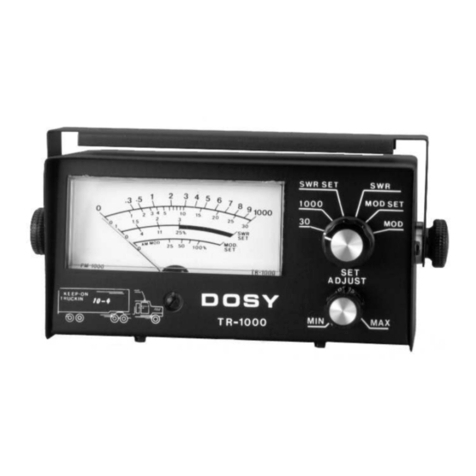
Dosy TR-1000 User manual

Dosy

Dosy TR-1000 User manual

Popular Test Equipment manuals by other brands

Agilent Technologies 3070 Series Site Preparation

Agilent Technologies

Agilent Technologies 3070 Series Site Preparation

Bartington SCU1 Operation manual

Bartington

Bartington SCU1 Operation manual

Keysight Technologies 85051B User's and service guide

Keysight Technologies

Keysight Technologies 85051B User's and service guide

GE Druck DPI 620 Safety and quick reference guide

GE

GE Druck DPI 620 Safety and quick reference guide

HT Instruments HT8051 user manual

HT Instruments

HT Instruments HT8051 user manual

Fluke A40B instruction manual

Fluke

Fluke A40B instruction manual

GW Instek GPT-9801 user manual

GW Instek

GW Instek GPT-9801 user manual

R&S RTO6 user manual

R&S

R&S RTO6 user manual

Indu-Sol PROFview XL user manual

Indu-Sol

Indu-Sol PROFview XL user manual

spectratime iTest+ PicoTime-1U Use

spectratime

spectratime iTest+ PicoTime-1U Use

Owon VDS Series quick guide

Owon

Owon VDS Series quick guide

Elma Instruments CM01A user manual

Elma Instruments

Elma Instruments CM01A user manual

AEMC MA114 user manual

AEMC

AEMC MA114 user manual

Hillstone HACM415-250X operating manual

Hillstone

Hillstone HACM415-250X operating manual

Tektronix 222 Operator's manual

Tektronix

Tektronix 222 Operator's manual

Teledyne Lecroy T3DSO3000 user manual

Teledyne Lecroy

Teledyne Lecroy T3DSO3000 user manual

Topdon BT200 user manual

Topdon

Topdon BT200 user manual

Klein Tools VDV Scout Pro 3 instruction manual

Klein Tools

Klein Tools VDV Scout Pro 3 instruction manual

manuals.online logo
manuals.online logoBrands
  • About & Mission
  • Contact us
  • Privacy Policy
  • Terms and Conditions

Copyright 2025 Manuals.Online. All Rights Reserved.