Doug Fleenor Design DMX24DIM User manual

Page 1 of 5
Models DMX24DIM and DMX24DIM-2U
Installation and Operations Manual
Doug Fleenor Design, Inc.
396 Corbett Canyon Road
Arroyo Grande, CA 93420
(805) 481-9599 Voice and FAX
Manual revision
May 2019

Page 2 of 5
Product description
The DMX24DIM and DMX24DIM-2U are 24 channel, 100 Watt per channel dimmer packs. They are
fed by a single 120VAC 15A branch circuit. Each of the dimmers can be separately controlled using
a DMX512-based lighting controller. The DMX24DIM and DMX24DIM-2U are housed in enclosures
suitable for portable use or for mounting in a standard 19" rack. The DMX24DIM occupies 1U of rack
space. The DMX24DIM-2U occupies 2U of rack space. The DMX24DIM uses two conductor
ungrounded outlets while the DMX24DIM-2U provides grounded parallel blade output connectors.
Safety warnings
$There are no user serviceable parts in the DMX24DIM or DMX24DIM-2U. Servicing should be
referred to qualified service personnel.
$Do not connect or disconnect loads to the DMX24DIM or DMX24DIM-2U with the power on.
Environmental
Operating temperature: 0-40º C
Operating humidity: 10-90% non-condensing
Indoor use only
Electrical ratings
Input: 120VAC, 60Hz, 15A
Output: 24 outputs, 120VAC, 100W each, 1800W maximum total
Certification
The DMX24DIM and DMX24DIM-2U are ETL Listed under safety Standard UL 508
Mounting/installation
The DMX24DIM or DMX24DIM-2U can be used as a portable unit or it can be mounted in a standard
19" equipment rack. Care must be taken to allow for unobstructed airflow around the unit. There
must be at least 6 inches of clearance in front of the DMX24DIM or DMX24DIM-2U and two inches of
clearance on the left side of the enclosure (as viewed from the front panel). No blank spaces are
required above or below the DMX24DIM or DMX24DIM-2U when it is rack mounted.

Page 3 of 5
Power input (line) wiring
The DMX24DIM should be connected to a standard 15A 120VAC grounded outlet. The outlet must
be protected by an appropriate over-current protection device.
Note that if all outputs are loaded to 100W and all outputs are set to full, the 15A branch breaker
feeding the DMX24DIM or DMX24DIM-2U will trip. If the application requires all dimmers to be fully
loaded, the DMX24DIM or DMX24DIM-2U must be fed by a 20A branch breaker and an appropriate
receptacle. The standard 15A mains plug on the DMX24DIM or DMX24DIM-2U must be replaced
with an appropriate 20A connector.
Power output (load) wiring
Each output can supply a 100W (maximum) 120VAC load. Each output on the DMX24DIM uses a
polarized ungrounded parallel blade connector (NEMA1-15R). The DMX24DIM-2U uses grounded
parallel blade connectors (NEMA5-15). Cables should only be connected and disconnected while the
dimmer outputs are off or the input power to the unit is removed.
Control cable wiring
Standard 5 pin XLR cables should be used to connect DMX512 signals to the connectors on the front
panel of the DMX24DIM or DMX24DIM-2U. A male input is provided and a passive female “thru”
output is provided. There is no internal termination. The last device in the DMX512 daisy chain
should be fitted with a DMX512 terminator.
Only pins 1, 2, and 3 are used by the DMX24DIM or DMX24DIM-2U, however all 5 pins are passed
through to the “thru” connector.

Page 4 of 5
Setting the address switches
The front panel address switches are used to select the DMX512 starting address for the DMX24DIM
or DMX24DIM-2U. Any starting address from 1 - 512 can be selected. The address shown on the
switches will be the DMX512 address for the first dimmer output. The next 23 consecutive DMX512
levels will be applied to the remaining dimmer channels.
When the address switches are set to 000, the DMX24DIM or DMX24DIM-2U operates as if the
address switches were set to 001.
The address switches are also used for a local test function described below.
Local control
Local control mode is used to turn on an output without the use of a DMX512 signal source. To use
local control, set the DMX address switches to 601 to turn on channel 1, 602 for channel 2, etc.
LED indicators
The LED indicators on the front of the DMX24DIM or DMX24DIM-2U have the following functions:
LED label
Function
SIGNAL
On when DMX is present, flashes when local control is active
MIMIC 1
Tracks the current level of dimmer 1 for troubleshooting purposes
PWR
On when power is on
Loss of DMX512 signal
Upon loss of the DMX512 input, the DMX24DIM will begin fading all of its outputs to zero. The fade
out time is about 60 seconds from the loss of signal.

Page 5 of 5
Maintenance and cleaning
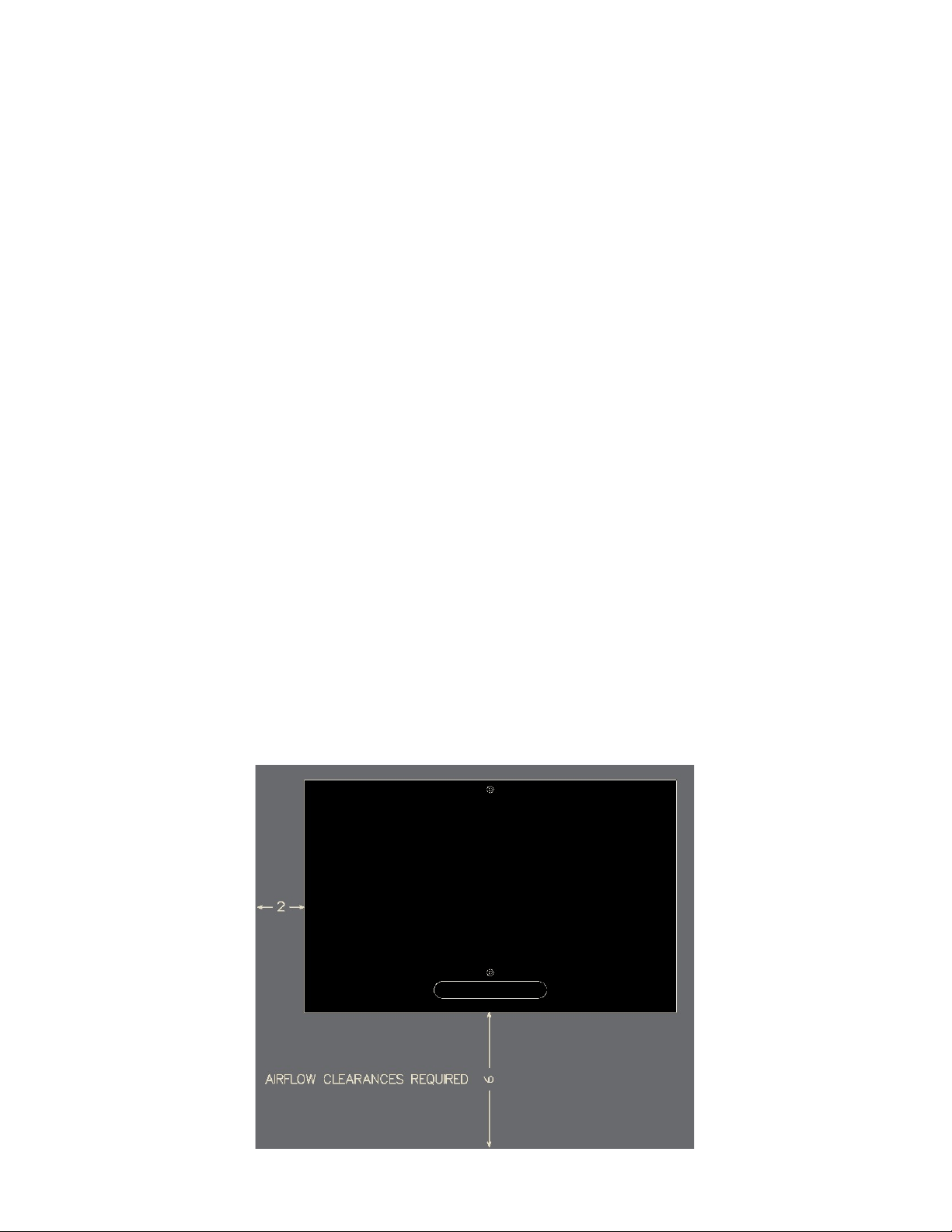
The DMX24DIM or DMX24DIM-2U’s fan intake on the front panel and the exhaust ports on the left
side of the enclosure should be cleaned periodically (see photos below). The frequency of cleaning
depends upon the working environment and the amount of time the dimmers are running.
Compressed air and a soft cloth should be used to remove excess dirt and lint. Power to the
DMX24DIM or DMX24DIM-2U must be disconnected while cleaning.
Fan operation
The fan in the DMX24DIM or DMX24DIM-2U will run any time any of the levels of any dimmer in the
pack is above 0%. The fan will continue to run for about 30 seconds after all dimmers are at zero.
Limited Manufacturer's Warranty
Products manufactured by Doug Fleenor Design (DFD) carry a five-year parts and labor warranty
against manufacturing defects. It is the customer's responsibility to return the product to DFD at the
customer's expense. If covered under warranty, DFD will repair the unit and pay for return ground
shipping. If a trip is necessary to the customer's site to solve a problem, the expenses of the trip must
be paid by the customer.
This warranty covers manufacturing defects. It does not cover damage due to abuse, misuse,
negligence, accident, alteration, or repair by other than by Doug Fleenor Design.
Most non-warranty repairs are made for a fixed $50.00 fee, plus shipping.
Doug Fleenor Design, Inc.
396 Corbett Canyon Road
Arroyo Grande, CA 93420
(805) 481-9599 voice and FAX
(888) 4-DMX512 toll free (888) 436-9512
web site: http://www.dfd.com
e-mail: info@dfd.com
This manual suits for next models
1
Table of contents
Other Doug Fleenor Design Dimmer manuals
Popular Dimmer manuals by other brands

thomann
thomann Botex UP-2 user manual

Perel
Perel 7500-3BD quick start guide

elsner elektronik
elsner elektronik RF-L UN-ST Technical specifications and installation instructions

myTEM
myTEM SmartHome MTSWD-100-WL Quick start quide

QUBINO
QUBINO ZMNHWD1 user manual

ENKIN
ENKIN SS-EN-00-PDM250 quick start guide