Dove Lighting Systems DimmerMaster User manual

DimmerMaster Shoeboxes
Wall Mount Dimmer Packs
User Manual!
Dove Lighting Systems, Inc.
3563 Sueldo Street, Unit E
San Luis Obispo, CA 93401
805-541-8292
www.DoveSystems.com
WALL MOUNT SHOEBOX - USER MANUAL
1

Table of Contents
Receiving Your Unit 3
Features 3
Installation 4
Mechanical Installation 4
Electrical Installation 5
Grounding 6
Load Connections 6
Control Connections 7
Control 8
Starting Channel 8
Load Test & Local Control 9
DMX Termination 10
Non-Dim & Emergency On Functions 10
In Case of Trouble 10
Troubleshooting 10
Obtaining Service 11
WARRANTY INFORMATION 12
WALL MOUNT SHOEBOX - USER MANUAL
2

Receiving Your Unit
As soon as you have received your equipment, open the boxes and examine the contents. If
the equipment in the carton does not match with your order or the packing slip, contact the
factory immediately and we will be happy to help you. If any damage is noted, contact the
carrier immediately to file a claim for damages. You can be sure that when the equipment left
the factory it was in capable condition, thoroughly tested, and properly packed.
Features
This manual covers Dove Lighting Systems, Inc.’s line of wall-mount DimmerMasters:
DM124-WM and DM412-WM.
The DimmerMaster “Shoebox” Dimmer is a compact unit with four 1200W dimmers in the 412
and one 2400W dimmer in the 124. It may be wall mounted in a standard 8” x 8” electrical
junction box and is perfect for tight spaces where conventional rack mount dimmer packs are
too bulky. Drawing no more than 40 Amps (20 for the DM124), it may be powered from a
single 120VAC circuit. By request when ordering, it may be configured for 240V input for use
with 240V lamps in regions (such as Europe and South America) with 240V systems.
WALL MOUNT SHOEBOX - USER MANUAL
3

The unit accepts both DMX-512 and 0 to +10VDC control signals. The unit will let the higher
of the two inputs (highest takes precedence, HTP) set the output level per channel. The
starting DMX channel is set on the thumbwheel switch, which also provides load testing and
local control. A status LED indicates the presence of a DMX signal. The control signals may
be daisy-chained from pack to pack on the screw terminals. Also available on the screw
terminals are contacts for +15VDC power and a remote Force On switch. The DMX signal
may be terminated at the last pack by means of a DIP switch. Other switches set individual
outputs for non-dim operation or force all outputs to full-on.
Another factory option that can be specified for the front panel at order time is either a neon
lamp indicating that the unit is receiving power or a push-on / push-off switch to force all
channels full-on.
Installation
Mechanical Installation
The dimmer pack is designed to fit Milbank 884-SC1, or equivalent 8" x 8" x 4" screw cover
enclosures (not included). The electrical box mounting holes are spaced 7.4” x 6.0”.
Maximum air temperature must not exceed 40°C (105°F). It is essential that this unit have
adequate cooling for safe, reliable performance.
WALL MOUNT SHOEBOX - USER MANUAL
4

Electrical Installation
The DM412-WM pack consists of four 1200W dimming channels, not to exceed 4800 Watts
total, and the DM124-WM has one 2400W dimming channel. They require a source of 120
Volts AC 50/60Hz with current capacity 40 or 20 Amps, respectively.
The actual amount of power consumed is determined by the total wattage of the connected
loads used; the dimmer itself consumes negligible power. It is recommended that no other
equipment be connected to the circuit which is used for the pack, including other outlets on
same fuse or circuit breaker. If the building circuit breaker trips, it may be necessary to
reduce one of the loads.
Line to neutral voltage is always 120 volts (unless the 240V version has been special
ordered). It is very important that the input voltage be checked with a meter to insure that it is
correct. A mistake can place 208 to 240 volts across a 120 volt lamp. The breaker will protect
the unit but may not save the lamp. A double check of voltages before applying power can
guard against such disaster.
The power input connector is a terminal block. The power feed connects to the terminal
marked “L.” The neutral connection is made on the terminal to its left marked “N.” The ground
connection is made on the ground terminal on the right end and labeled “G.” The pack has
circuit breakers to protect each dimmer channel, but the primary circuit protection and
disconnect is to be provided by the user. A single pole 20 to 40 amp circuit breaker is
required.
When power is connected, the neon power indication lamp will light up (if so equipped). In
addition, the status LED will light up in red (60Hz line), yellow (50Hz line), and turn green
when a DMX signal is present.
WALL MOUNT SHOEBOX - USER MANUAL
5
DM412-WM Power Terminals
DM124-WM Power Terminals

Warnings: This device is required to be connected to a building electrical circuit with over
current protection corresponding to the input current on the equipment label.
Grounding
The term “grounding” refers to a separate wire, usually with green insulation, which is
connected from the equipment case to earth ground. This is not the same as the neutral or
common and must not be confused with them. The neutral is a separate, load-carrying
conductor, and common refers to the control signal’s common or reference voltage which
should only be allowed to reach ground at a single point in the entire system (typically at the
control console) to avoid ground loops.
Load Connections
The pack will dim any load up to 1200W per channel on the DM412 or up to 2400W per
channel on the DM124. The load may be incandescent, inductive or resistive. This includes
conventional incandescent, quartz incandescent, “rain lights", pin-beams, and similar "low-
voltage" lighting loads containing transformers. Fluorescent and neon loads can be controlled
by the Shoebox with no damage to the dimmer, but the nature of these loads requires
specialized circuitry to get full range dimming. Consult the factory if you need to dim such
loads.
WALL MOUNT SHOEBOX - USER MANUAL
6
Com
+12V
Clr
Out1
Out2
Out3
Out4
Clr
Take
+12V
HLC-4
Com
+12V
Clr
Take
HLC-0 G
L
N
4
3
2
1
DM412
DMX Data
C - + - +
1 2 3 4 5
4 3 2 1 Com
from DMX
console
power
from
breaker
!!!!
+15
Example Wiring Diagram of DM412-WM, HLC-4, and HLC-0

Many “dimmable” LED bulbs work fine with the Shoeboxes (though it’s common for them to
only dim to about 10% before turning completely off which can be disappointing), and the
percentage of those in the market continues to increase with time as bulb manufactures
improve their circuitry’s compatibility. Still, some LED bulbs will flicker at low power levels.
There are a few approaches to dealing with these bulbs: The easiest is to test several
different bulb models, and just avoid the trouble makers. Some control consoles can be
programed to avoid the problematic low power levels. In some cases, the flickering can be
mitigated by adding parallel loads in the form of a low power incandescent bulb or resistors.
Dove Systems offers factory installed 4.7kΩoutput resistors by special order or retrofit.
On the DM412-WM, there is one terminal for each output and two larger output neutral
terminals. On the DM124-WM, there is one output terminal and one output neutral terminal.
Terminals are labeled according to their circuits, see photos above. There should be a
separate neutral returning from each load circuit.
Each output channel is protected by a 10 Amp circuit breaker (20A on the DM124). If a circuit
breaker trips, it is generally due to an overload or short in the output load. However, elevated
ambient temperatures or lack of ventilation can also result in breakers tripping just shy of their
rated current.
Control Connections
The pack accepts both DMX-512 and analog 0 to +10VDC control signals. DMX control
signals are input through the first three terminals (Common, Data-, and Data+) of the 12
WALL MOUNT SHOEBOX - USER MANUAL
7
Control Terminal Block (Neon Power Indicator option shown)

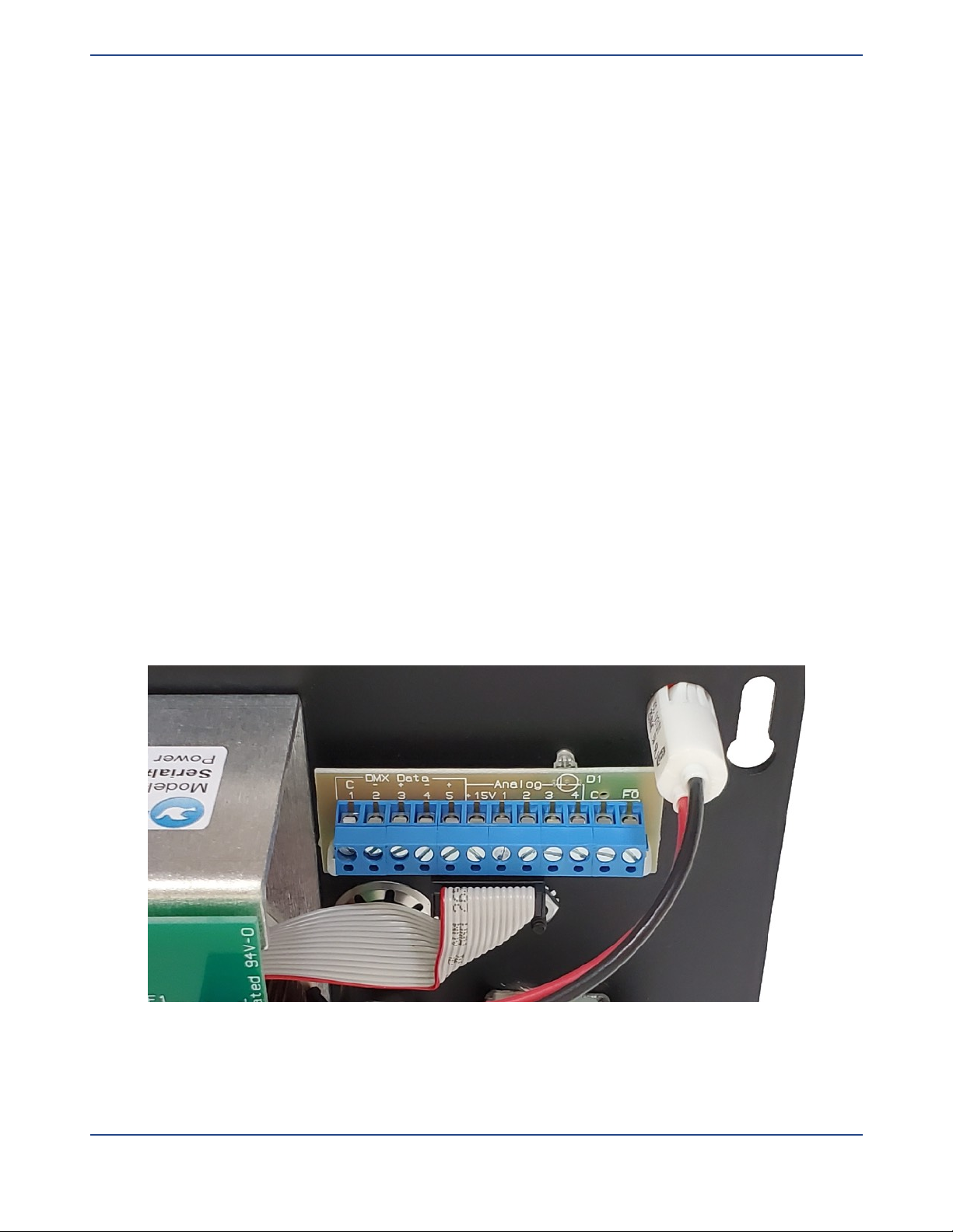
contact control terminal block. Each terminal is large enough to accommodate multiple signal
wires so the control signals can be easily daisy-chained from pack to pack. However, do not
create Ys in the DMX signal path as these can lead to signal integrity issues that result in
poor reliability and flickering. Instead, use one of the specialty interface boxes for this
purpose (for example, the Dove DMX-Y).
Terminals 4 and 5 are typically not used, but can be used to aid in splicing another pair of
signal wires like a second DMX universe. DIP switch 9 will connect Terminal 5 to +15V when
in the on position and should be loaded with less than 100mA. This is an unregulated power
source and will typically vary between 12 and 18 Volts. Under no-load conditions it can reach
25V. An example application of this feature would be to power a Dove DMX-Y.
Terminal 6 is +15VDC referenced to Common. This is an unregulated power source and will
typically vary between 12 and 18 Volts. Under no load conditions it can reach 25V. It will
typically source over 200mA before dropping below 12V. This source is typically used to
power the Dove 0-10V House Light Controls or our DMX-Y.
Terminals 7 through 10 are 0-10V analog control inputs for outputs 1 through 4 respectively.
(The DM124-WM ignores terminals 8 through 10.) The higher of the analog or DMX for a
given channel will take precedence (HTP). Terminal 11 is the common for these analog inputs
and therefore must be connected to the analog control source as well. It is also connected to
Terminal 1 internally.
Finally, Terminal 12 is the Force-On input. When this terminal is connected to common
(Terminals 1 & 11), all channels will be turned on to 100% overriding any DMX or Analog
control signals. The Wall Mount DimmerMasters’ push-button option replaces the standard
Neon Power Indicator with a push-button connected to Terminals 11 & 12. One can easily
connect a remote switch to activate this feature on one or multiple dimmers for use as a
“maintenance light switch.” Multiple dimmers are likely already sharing a common for their
DMX and/or Analog inputs, so a wire would only need to be added to terminal 12. Also, keep
in mind that this input can be useful in troubleshooting the lighting system.
Control
Starting Channel
The starting channel is set on a thumbwheel switch. When the switch reads 001, the dimmer
pack runs on DMX channels 1 - 4. Setting 005 runs on channels 5 - 8, setting 009 runs on
channels 9 – 12, and so on. Valid addresses range from 001 to 509 (512 for the DM124). The
starting dimmer may be any channel, and dimmers on different packs can overlap some
channels, though it is usually preferred to run them one dimmer per channel. Dimmer
WALL MOUNT SHOEBOX - USER MANUAL
8

channels should not overlap channels for other DMX equipment, including strobe lights, & fog
machines. It is not necessary to set the starting channels in sequence (ie. 1-4, 5-8, 9-12).
The Wall Mount DimmerMasters have a heat-shrink guard around the thumbwheel switch.
While this can make it a little more challenging to manipulate the buttons, it generally
prevents the settings from being inadvertently changed by bumping into wires as the unit is
installed in the electrical box enclosure after configuration — a far more frustrating issue to
troubleshoot.
Load Test & Local Control
The thumbwheel switch enables the load testing / local control functions. The load test is
useful for determining which load is plugged in. Set the first digit to 6 and the second digit to
the dimming channel (from 1 to 4, but only 1 on the DM124). Set the third digit to the dimming
level, from 0 (off) to 9 (full on). Levels thus set remain in effect until the power is disconnected
or control is returned to DMX.
Here is an example:
•Set the thumbwheel switch to 600 for local control.
•Set the second digit to 1 to control the lamp on channel one. Set the third digit to 5 to put
lamp one at half power. (The first load will now stay at half power)
•Next, set the second load to half power by setting the thumbwheel to 625. (The first and
second load are now both at half power)
•Finally, set the thumbwheel to 639. This will set the third load to full on while leaving the
first two loads at half power.
A Crossfade Chase function is also available for stand alone operation without a DMX
source. Set the thumbwheel switch to 701 through 799 and the unit will perform a crossfading
chase with 1 (701) to 99 second (799) steps between each of the four channels. On the
single channel DM124, the chase function only fades the channel up and down with a 50%
duty cycle.
Example:"
Thumbwheel switch is set to 710. The unit will then crossfade from channel #1 to channel #2
in 10 seconds. Then the unit will crossfade from channel #2 to channel #3 in ten seconds,
from channel #3 to channel #4 in ten seconds, and then back to channel #1. This will repeat
until you change the thumbwheel setting or power down the unit.
To return to DMX operation, set the thumbwheel switch to the DMX start channel of your
choice (1-512).
WALL MOUNT SHOEBOX - USER MANUAL
9

DMX Termination
DMX termination may be made on the DIP switch 1 on the circuit board. Signal reflections
can cause corruption of the DMX-512 data, typically causing flickering or flashing of lights in
systems with long (>100 ft total) cable runs. Only the last pack in the chain should have
termination enabled.
Non-Dim & Emergency On Functions
In addition to DMX termination (DIP1), the DIP switches 3 through 6 set individual channels
(1-4 receptively) for non-dim (full on or off) operation. The DM124 ignores DIP4-6. In non-dim
mode, the dimmer forces that channel on when it receives a DMX value of 50% or more and
turns the channel off when it receives a DMX value less than 50%.
The Emergency On function, DIP2, forces all outputs on regardless of the control level — an
easy first step when troubleshooting.
If the external Force On (Terminal 12 of the control terminal block) is connected to other
dimmer packs, they will also be turned on. However, this would be a very unusual condition
since the DIP Switches are not accessible when the Wall Mount DimmerMasters are fully
installed in their enclosures.
In Case of Trouble
Troubleshooting
A review of the following paragraphs may save you the cost of a service visit or of shipping
and repair. Even if something is still wrong, this process will help you explain the malfunction
to the service technician.
First, read the operating instructions carefully. Be sure you know how to operate the
equipment. Do not expect this equipment to operate exactly like others. Many apparent
failures result from not being familiar with the unit’s operating characteristics.
Check all lamps and wiring for shorts that can cause damage to the dimmers.
There are three forms of malfunctions common to solid state dimmers:
•“Failed Off” (in which the lights do not come on)
•“Failed On” (in which the lights are on only)
•“Flickering” (where the levels will not maintain)
WALL MOUNT SHOEBOX - USER MANUAL
10

If a load has "failed off,” check that the instrument is plugged in and that the lamp has not
burned out. Verify that the dimmer pack is on (the LED will glow). Use the load test feature
(see above) to see if the load can be controlled at the pack. Check if the circuit breaker on
the unit needs to be reset — the button with the current rating on it will pop out, just push it
back in to reset. Check that the control cable runs all the way back to the controller without
damage and that the signal has not been terminated at a pack somewhere up the chain.
Check the controller, paying particular attention to the softpatch feature if so equipped.
If a load has "failed on,” especially after resetting a breaker, it is probably due to a shorted
triac. Triacs can fail when a short in the output overloads it faster than a circuit breaker can
protect it. The short can be in the cable, in the connectors, in the light fixture, or in most often
the lamp itself. Please check the load by plugging it into a known good wall outlet before
plugging it into other dimming channels.
Flickering can be the result of a failing control console. Try an alternate control source or
console power supply.
Channels which flicker or cut in and out can be victims of an intermittent connection
somewhere, including broken slide controls. This can occur if dirt, coffee, or some other liquid
is spilled into the slide control slot. Curing this problem usually requires the replacement of
the control. Cleaning with WD-40 or TRI-FLOW may fix it temporarily.
Sometimes flickering is caused by a problem with the control cable. If DMX termination has
not already been set at the last pack, set it. Crushed or pinched cables can cause intermittent
failures. Try an opto isolator to eliminate any potential control cable ground loop problems.
Swap control cables. Route them away from motors or other sources of noise. Do not use
passive splitters.
In some installations, a Shoebox’s breaker may trip after a long time in use. This is most likely
to occur when a channel is loaded at or near its maximum rating and there are high ambient
temperatures or limited ventilation. The solution will be to either decrease the load or improve
cooling. Cooling can be improved by increasing the free space around the unit. They should
never be installed in an enclosed space without plentiful free flowing air.
Obtaining Service
We are always happy to help you troubleshoot. Emailing photos of the situation to
805-541-8292.
Service technicians are generally available between the hours of 8am to 3pm (Pacific Time)
Monday through Friday. It is helpful to have a complete description of the problem and to be
in the theatre or otherwise have access to the equipment when placing the call.
WALL MOUNT SHOEBOX - USER MANUAL
11

It is recommended that all equipment be repaired at the factory. If the unit is under warranty, it
MUST be repaired at the factory. Replacement parts are available, but because the
DimmerMaster packs are microcontroller based product running proprietary software,
schematics CAN NOT be released.
To obtain service, please visit the Repairs page of our website, http://
www.DoveSystems.com/repairs, download the Repair Form, and follow the instructions. We
will get your Shoebox operating like new and return it quickly.
WARRANTY INFORMATION
The manufacturer agrees that the DimmerMaster shall be free from defects in material or
workmanship from date of shipment over a period of one year. Said warranty will not apply if
equipment is used under conditions of service for which it is not specifically intended. The
manufacturer is not responsible for damage to its apparatus through improper installation,
physical damage, or poor operating practice. If any device is found unsatisfactory under the
warranty, the buyer should notify the manufacturer, and after receipt of shipping advice, buyer
may return it directly to Dove Systems, San Luis Obispo, CA, shipping prepaid. Such
equipment will be replaced or put in proper operating condition, free of all charges except
transportation. The correction of any defects by repair or replacement by the manufacturer
shall constitute fulfillment of all obligations to the purchaser. Manufacturer does not assume
responsibility for unauthorized repairs to its apparatus, even though defective.
Manufacturer shall not be liable for any consequential damage in case of any failure to meet
the conditions of any warranty of shipping schedule, nor will claims for labor, loss of profits,
repairs, or other expenses incidental to replacement be allowed. No other representations,
guarantees or warranties, expressed or implied, are made by the manufacturer in connection
with the manufacture and sale of its equipment. This warranty is non-transferable and applies
to the original buyer only.
Copyright Dove Systems, 2021
WALL MOUNT SHOEBOX - USER MANUAL
12
Table of contents