2. FRAME INSTALLATION AND SERVICE MAINTENANCE
2.1 Net Opening and Frame Installation
Read instructions completely before installing the frame. Before installing the frame, confirm
that the size of the net opening accommodates the finish frame, net opening should be 1/8”
larger than the frame size, this is 1/16” all around equally gap around the frame. If the
tolerances exceed 3/8”, the net opening will have to be enlarged. Refer to Figure below for
clarification.
• Proper framing, insulation, and clearances for openings (case bottom or floor are mandated
by local building codes). Ensure that your opening meets these code requirements prior to
attempting frame installation.
• Sill net opening height must be at a minimum of two inches.
• Sill, Header and Jack Studs must be completely square, level, and free of any debris that may
interfere with frame sitting flush to sill.
• If the gap between the frame and the net opening is greater than 1/16”, shim the gap for a
proper fit (refer to “Shimming Frame”).
2.2 The following instructions will ensure proper frame installation:
1. When installing frame, DO NOT install Frame directly on Sheetrock, frame is designed to be
installed to Cooler/Freezer Boxes only
2. Ensure that the Sealing Frame Flap is fully engaged the to Sill, Header, and Jack Studs creating
a seal without any gaps (see Figure 2.0)
3. Make sure to DO NOT force the frame if the fit is too tight, doing so may cause you to break the
Sealing Frame Flap or tweak the Frame.
4. Insert a mounting screw into a mounting hole in each corner of the frame and tighten each screw
until it is approximately a quarter inch from flush.
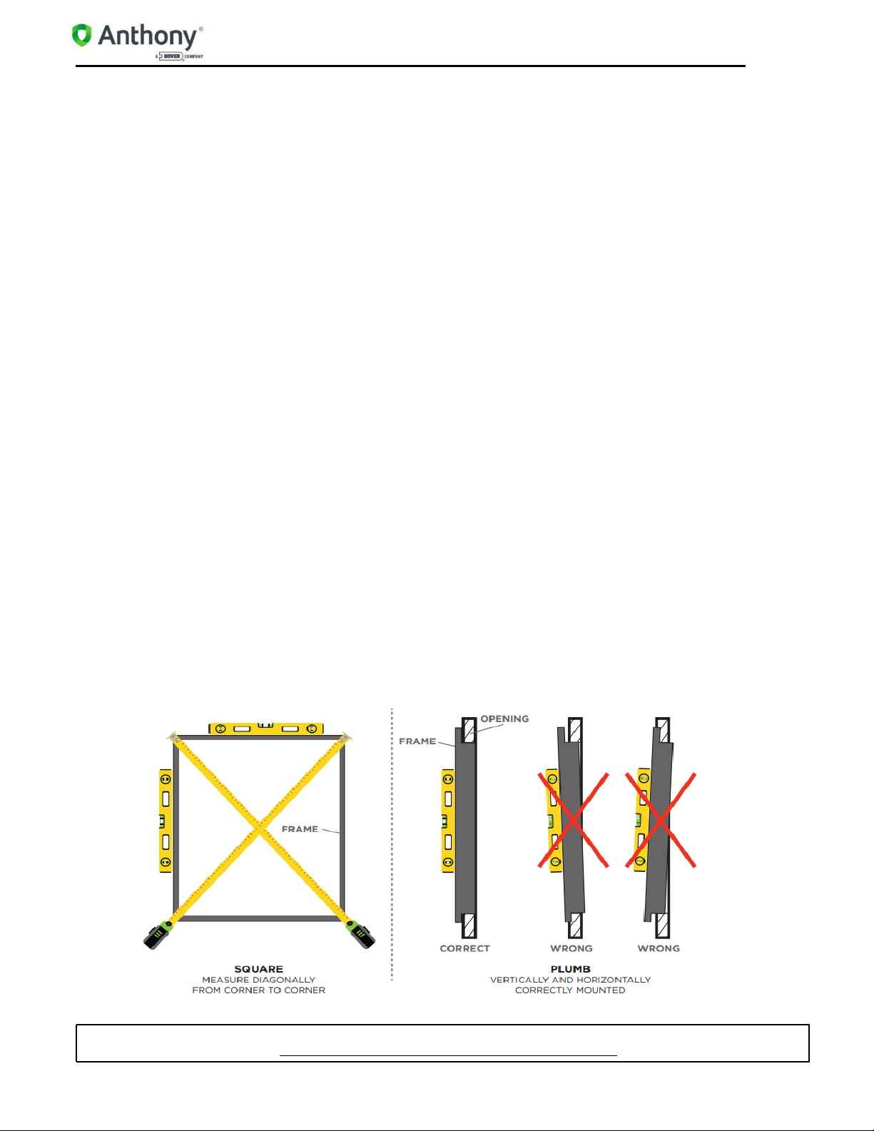
5. Check the frame is aligned properly or square.
6. Use a measuring tape to measure diagonally one corner to the opposite and note the distance.
7. Measure the distance between the remaining two corners.
8. Both measurements should be the same, or within a 1/16” difference.
9. Confirm the frame and frame flanges are vertically and horizontally aligned (plumb) to the wall
surface around the net opening.
10. Place a level on the top flange of the header frame to check if it is horizontally aligned.
11. If the top of the header frame sags or bows, correct as necessary.
12. When the frame is completely aligned, tighten all mounting screws securely until each is flush
to the frame surface. DO NOT over-tighten the screws, as this can cause the frame to become out
of square.
13. Check entire frame to ensure installation is correct. If needed see refer to “Shimming Frame”
section for instructions on how to use shims to align frame properly.
2.3 Shimming Frame
Shimming is only to be used when necessary and will primarily be done at the header (top) of
frame and opening. If the gap between the frame and net opening is greater than 1/16”, proceed to
shim the gap for a proper fit.