Dover Hydro systems AquaBlend 0.2%-2% WSP User manual

Operating Manual - Adjustable Lower End
Fluid Flow Range:
0.04 gpm to 11 gpm
10-2500 l/hr
Injection Range:
0.2% to 5%
1:500 to 1:20
Operating Pressure:
5 to 90 psi
0,3 to 6,2 bar
Model 0.2% - 2% WSP
Model 0.78% - 5% WSP

Quick Start Guide
0.04 – 11 gpm 5 – 90 psi
10 – 2500 l/h 0,34 – 6,2 bar

This document does not form a contractual engagement on the part of Hydro Systems and is for
information only. Hydro Systems reserves the right to alter product specications or appearance without prior notice.
For Your Records
The serial number of your Hydro Systems injector is
located on the injector body. Please record this number
in the space below and reference it when calling your
distributor or Hydro for information, parts and service.
Serial #..............................................................................
Date Purchased ................................................................
Please read this manual carefully before putting the Hydro Systems injector into
operation.
This booklet has the information you will need for the use and care of your new Hydro Systems
injector. If you have any further questions about your injector, the warranty, routine maintenance or
proper usage, please contact your nearest distributor or Hydro Systems customer service.
These models are designed to inject liquid concentrate or soluble powder that are recommended
and approved for injection into uid systems.
lt is the responsibility of the operator to determine the correct dosage settings of the unit using the
chemical manufacturers’ recommendation for dispensing their product, and to assure that proper
dosage is being maintained.
Maintenance and Warranty
Hydro Systems offers a one year limited warranty from the original date of purchase for
manufacturing or materials defects only. With proper use and care, your injector should provide you
long-term performance. Please review the complete warranty information on page 14.
Contents
Package Contents ............................................................................................................4
Specications ..................................................................................................................4
Safety Precautions ...........................................................................................................5
Warranty Compliance .......................................................................................................5
General Tips ....................................................................................................................5
Operations .......................................................................................................................6
Installation and Start-up ..................................................................................................7
Suggested Installation Diagram .......................................................................................7
Maintenance ...................................................................................................................8
Routine Maintenance Instructions ....................................................................................9
Troubleshooting .............................................................................................................10
Injector Repair Parts .....................................................................................................11
Lower end injector parts 0.2% - 2% Wettable Powder: ...................................................12
Lower end injector parts 0.78% - 5% Wettable Powder: .................................................13
Warranty ........................................................................................................................14
Contact .........................................................................................................................15

4
Specications
Package Contents
AquaBlend Injector (not shown) Mounting Bracket
Dosage gasket Mounting Pins
Quick Start Guide (not shown) Filter
Suction Tube
The injector is packaged
with the following items: Wettable Powder
NPT BSP
0.2% - 2% 117947WSP 117957WSP
0.78% - 5% 117948WSP 117958WSP
AquaBlend (90 max. psi)
Model 0.2% - 2% (1:500 - 1:50)
Model 0.78% - 5% (1:128 - 1:20)
Flow Rate: 0.04 - 11 gpm (10-2500 l/h)
Operating Pressure: 5 - 90 psi (0,3 - 6,2 bar)
Pipe Coupling: 3/4” npt/ght/bsp
Housing Polyacetal (POM)
Dosing Accuracy +/- 10% of ratio
Repeatability +/- 5%
Pressure Loss Available Upon Request
Maximum Temp. 100ºF/38=°C
Minimum Temp. 34ºF/ 1°C
Maximum
vertical suction of
concentrate
13 Feet/396
Centimeters
Maximum
horizontal suction of
concentrate
49 Feet/1493
Centimeters
Self-Priming Yes
Seal Material
Available:
Viton - acids, oils &
pesticides
Alternative material
available upon request.
Maximum Viscosity 2,000 cP (Ex. Honey)
Recommended
Accessories
140+ mesh lter, check
valve, pressure regulator,
ow restrictor.
56
195008
55
004014 (2x)
44
102004V
2%
44
194022V
5%
97
003035 (2x)
NPT models only
25
2% 10095359
5% 10095356

5
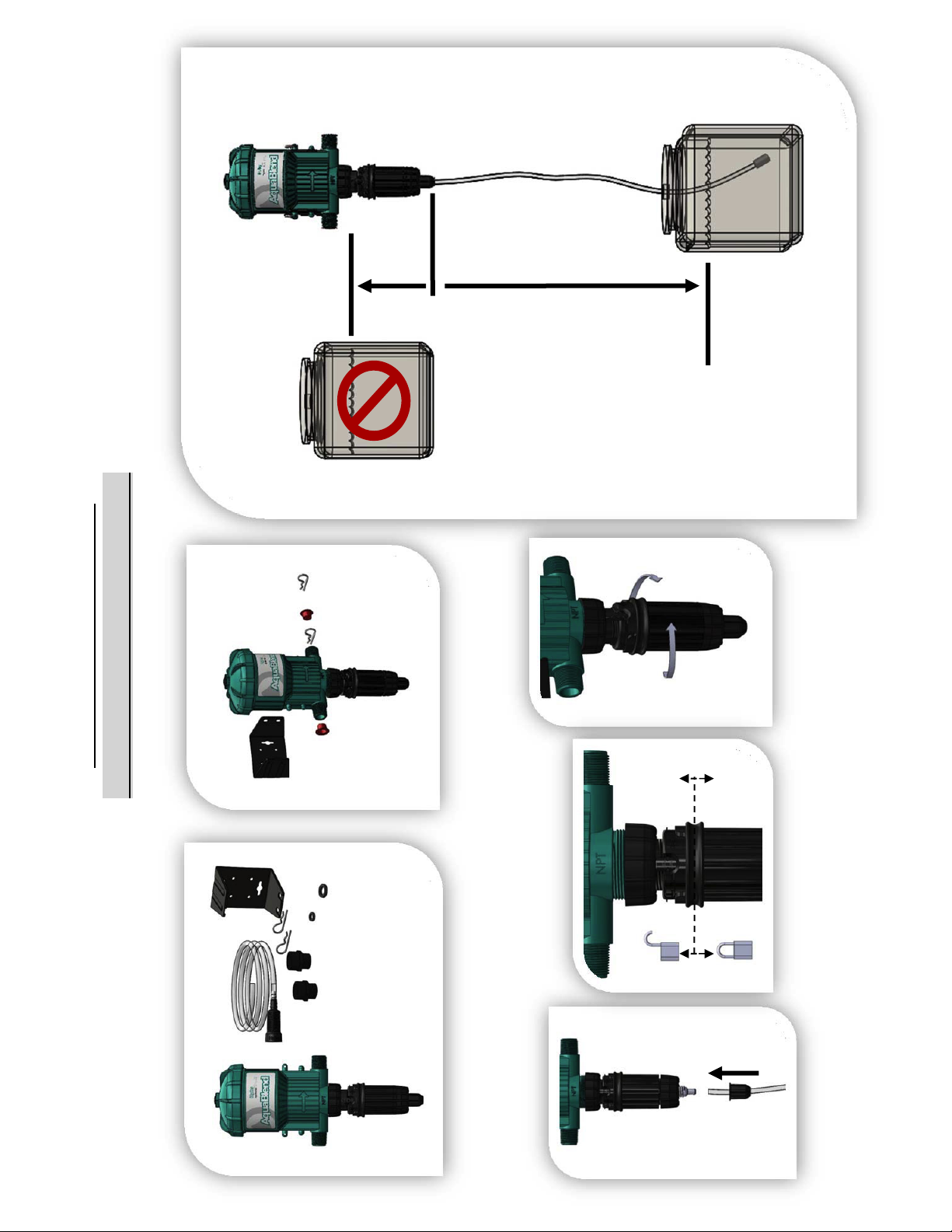
Remove Red Caps Prior to Installation
Your injector is 100% factory tested before delivery and
may contain a small amount of water. The three red
plastic caps are tted after testing to ensure cleanliness
of the injector.
Before Applying Aggressive Chemicals
Please consult your distributor, chemical manufacturer or
contact Hydro's customer service to conrm compatibility
with your injector. Always wear proper safety
protection as recommended by chemical supplier.
Label all Fluid Lines, Valves and Connections
If the solution that is being injected is not suitable for
drinking, all uid lines should be labeled:
Warning not for human consumption!
Monitor Outlet Flow
It is the user's responsibility to monitor the output of
chemical injected.
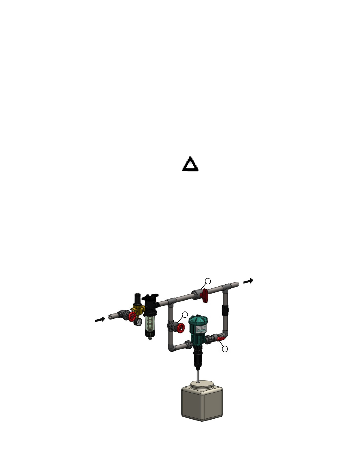
A Filter is Recommended and Required
Install a lter of 140 mesh (104 micron) or ner
depending on your uid quality to prolong the working
life of the injector and for the warranty to be valid. A
lter is imperative since most uid contains impurities or
particles, especially if the uid source comes from a well,
pond or lake.
Safety Precautions
Warranty Compliance
General Tips
For A Long Service Life
Start with clean uid by using an inline lter to reduce
impurities. Keep the solution container covered and
clean. Keep the suction tube lter off the bottom of
the container. Perform maintenance procedures as
recommended (see Maintenance page 8).
Soluble Powder Use
Ensure the chemical is completely dissolved before
starting the injector. If necessary, dissolve the chemical
in hot water and allow to cool before using. Failure to
thoroughly dissolve the chemical will cause premature
wear to the dosage piston/gasket and the inner cylinder.
!
Please read this instruction manual thoroughly. Following the procedures,
will increase the life of your injector.
Warning, Please read precautions thoroughly before operation. Must meet all applicable local codes and regulations.
Avoid a Potentially Hazardous Chemical
Accident
Select a safe location. Chemical container should be
kept away from children and/or high usage areas and
the location must also not be susceptible to freezing
temperatures.
Avoid Solution Contamination
Use only clean FILTERED uid. Do not allow
contaminants to enter the solution container. Dirt, debris
and other contaminants in the solution container may
cause excessive wear to the unit.
Fluid Temperature
Min: 34°F (1°C) Max: 100°F (38°C)
Maximum Fluid Pressure
90 psi (6,2 bar)
Install a pressure regulator and/or pressure relief valve to
ensure operating pressure does not exceed the maximum
specication.
Before Removing An Injector From The System
Release uid pressure. While the system is in operation,
turn off the incoming uid valve. Leave the out going
valve open this will relieve the pressure at the injector
and all parts of the system after the injector. Injector is
now safe to remove.
Keep From Extreme Temperature
Protect the injector from freezing temperatures or excessive
heat.
Rinse Injector After Each Use
Additive allowed to remain in injector can dry out, foul or
damage the lower end at the next start-up (see Maintenance
page 9).
Injector Not in Use for an Extended Period
If the injector has not been stored properly deposits may
have dried onto the motor (see Maintenance page 8).
Before operation, soak entire unit into room temperature
water approx. 72°F (22°C) for a 24 hour period.

6
Operations
Clicking Sound is Normal
Fluid owing through the injector will automatically cause
the injector to “click” and inject a set amount of solution
into the uid line. The higher the ow rate the more
frequent the "clicking". The injector is designed to inject
solution proportionally (at the same set ratio) regardless of
uid ow. Maximum number of clicks per 15 seconds
is 50.
Service Fluid Flow
Fluid ow and pressure must be within the established
specications (see Specication on page 4) for your
model.
Change Feed (Injection) Rate
The feed rate on the injector is adjustable EVEN WHILE
OPERATING AND UNDER PRESSURE. To change feed
rate see (Fig. 1 and Fig. 2). Do not remove #79 when
injector is under pressure.
1. Lift lock ring on (#7) (Fig. 1).
2. Rotate Ratio Adjuster Sleeve (bottom of #7) (Fig. 2) up
or down to the desired setting. Use arrows at top of the
Ratio Adjuster Sleeve to line up with the desired feed rate
on the sleeve.
3. Return ring to lock position by pushing down on ring.
NOTE: Do not screw Ratio Adjuster Sleeve below lowest
setting line. Measure outlet uid to assure desired feed
rate is being delivered.
Bleed Port
Ensure all air is out of the unit by pressing the bleeder
button in until water comes out. Release bleeder button
to stop water from owing out of bleed port.
Fig. 2
Fig. 1
Typical wall
mounting
Fig. 4
Lock Ring
Ratio Adjuster

7
Fluid Filter (Required)
Install a lter of 140 mesh (104 micron) or ner
depending on your uid quality to prolong the working
life of the injector and for the warranty to be valid. Hydro
recommends a Twist II Clean® lter that can be ordered with
your injector.
Mounting Injector
Securely fasten your injector to a solid object such as a wall or
in a cold uid line. Note arrow on injector indicates uid ow.
Backow Preventor (Recommended)
Install one that meets local code requirements.
Pressure Safety Release Device (Recommended)
Prevents pressure from exceeding specications of the unit.
Bypass Valve Set-up (Recommended)
Allows the injector to be taken off-line for maintenance
or storage when not in use.
Fluid-Hammer Arrester (Recommended)
Prevents uid-hammer damage to the injector when operating
quick closing solenoid, pneumatic or hand-operated ball
valves on the uid system.
Anti-Siphon Valve (Optional)
To prevent solution from being siphoned out (from the
solution container) into the feed lines when the upstream
valve is shut off. The anti-siphon valve must be installed on
the downstream outlet.
Additional Siphoning Prevention
Place solution container on a level below the injector suction tube
tting. Using the inlet side as a shut-off valve could cause full
strength solution to siphon into the feed line.
Solution Container
Use any size container. A lid or cover is recommended. To connect
your solution container, gently push the end of the suction tube
onto the bottom of the suction tube tting assembly.
Place the lter into the solution container at least 2" above the
bottom and ll with at least 2" (5cm) of chemical solution.
Never Use Petroleum Based Lubricants
The injector is shipped with a thin coat of silicone around the
seals for ease-of-assembly. Petroleum based lubricants such
as Vaseline©, baby oil, WD40©, or motor oil on the O-rings or
any part of the injector should never be used as this can cause
particles to adhere and clog or damage the injector.
Check System for Leaks and Start-Up Procedures
Open the bypass valve (A), close inlet valve (B) and outlet
valve (C) to prevent uid ow into the injector. SLOWLY
turn on the main uid line. Run uid ows between 5 -10 gpm
(1100-2200 l/hr) through the plumbing system. Turn on all of the
valves located downstream from your injector to release trapped
air. SLOWLY turn on the inlet valve (B). Open the outlet valve (C)
and close valve (A). As uid travels through the injector, you will
hear a “clicking” sound. Check for leaks and correct if necessary.
Installation and Start-up
Fig. 5
Refer to Fig. 4 and Fig. 5
Suggested Installation Diagram
!
A
B
C

8
RINSE INJECTOR AFTER EACH USE
Additive allowed to remain in injector can dry, foul
or damage the lower end at the next start-up. Place
suction tube into a 1 qt. (0.95 liters) or more container
of fresh ltered water. Flow fresh water through the
injector by operating until container is empty. This
procedure is not needed for continuous operation.
CLEAN SOLUTION CONTAINER
Keep covered to prevent dirt, and other debris from
entering the container. Rinse container thoroughly and
often. Do not mix chemicals together that might react
and cause a precipitate. Use FILTERED uid when
lling container.
CLEAN SUCTION TUBE FILTER SCREEN
Inspect each time new solution is added. Clean lter
screen and suction tube (#25) as necessary by rinsing
in fresh water. Replace if necessary. Keep lter screen
off bottom of solution container to prevent dirt and
precipitate from clogging lter.
CLEAN INLET FILTER
Clean or replace inlet lter as required to increase the
life of the unit as well as reduce pressure loss.
BYPASS INJECTOR
When not in use place the injector in bypass mode by
using the three valve bypass.
STORAGE
For extended storage, rinse injector using a minimum
of 1/2 gallon. (see "Rinse Injector After Each Use")
Drain water from unit. Inspect lower end seals. Apply
thin coat of silcone to seals and reassemble unit.
Place plugs back into inlet/outlet & suction tube
tting. KEEP FROM FREEZING.
Maintenance
Perform these maintenance
procedures to extend the life of your unit.
NOTE: Maintenance intervals may vary depending on
conditons of use and the chemicals being injected.
Every 3 - 6
Months
Every 6 - 12
months
Replace as
necessary
1. Clean Seal areas
#44.
2. Clean & Check
#64 Seal, #68
Cylinder, clean
and/or replace as
necessary.
3. Clean Filters
1. Replace Dosage
gasket #44.
2. Clean and/or replace
Check Poppet, inside
#11 Suction Tube Fitting.
1. #68 Cylinder
2. #64 O-ring/
Gasket
3. Motor Piston#9
4. #51 & #44
Shaft Assembly
Dosage gasket
5. Check Valve
Assy & Tubing
Reference numbers refer to Page 11-13

9
Routine Maintenance Instructions
Step 1.
Unscrew and remove
lower end from assembly.
Step 2.
Pull down on shaft, rotate shaft 90°
and remove.
Step 3.
Remove shaft with gasket and
install new. If damage on sealing
surface of shaft, replace shaft.
Step 6.
Place new motor piston carefully
into pump body and replace lid.
↓
Step 5.
Remove motor piston from
pump body.
Step 7.
Place shaft into the motor piston.
Step 9.
Replace lower end assembly onto
the pump body.
Step 4.
Hold body rmly and unscrew the
lid. If lid is tight, use 1" (25mm)
socket to loosen.
Step 8.
Rotate shaft 90° to lock into place.
Gently pull down to ensure shaft is
locked.
↓

10
New Install - Always Pressure Up Slowly (Follow start up on page 8)
Problem Cause Solution
No Clicking
Sound
Fluid not owing through unit
Are the red plugs at the inlet, outlet and suction tube tting openings removed?
Is the unit installed backward? The arrow on the unit must point in the
direction of the uid ow.
If still not clicking, do not open the upper body. Call Hydro Systems Customer
Service.
Fluid owing through unit
Fluid rate is below or exceeds rated service ow of injector. (see Specications
for maximum ow rate page 4). Maximum number clicks = 50 in 15 seconds.
Ensure all air is out of the unit by pressing the bleeder button in until water
comes out.
If below increase ow rate, if above, reduce ow rate.
Operating pressure exceeds maximum limit. Install a pressure reducer valve.
(see Specications for maximum ow rate page 4).
Problem Cause Solution
Clicking
Sound
No Suction Of
Solution
Cracked or loose Suction Hose Check for proper t and /or replace.
Dosage gasket #44 worn or
installed incorrectly
Replace. Ensure during maintenance replacement that #44 dosage
gasket was installed correctly.
Suction tube #25 or suction tube
tting #11 cracked, leaking or
clogged suction tube lter
Replace and/or clean as necessary.
Check valve #11 leaking Clean and/or replace as necessary.
Problem Cause Solution
Fluid
Re-lling
Solution Tank
Check valve #11 leaking or dirty Check seat area on suction tube tting #11. Check valve and seal must
t loose in the suction tube tting. Clean seal and inside tting for debris.
Washer seal on #11 is swollen or
chemical attack
Replace with new check valve assembly.
Problem Cause Solution
No Clicking
Sound
Air trapped in unit Release trapped air by pressing the bleeder button in until water comes
out.
By-Pass Valve not open Set Valve to the closed position.
Broken Springs Replace Springs #18, Clean Fluid Filter.
Dirty or plugged inlet lter Ensure mesh size is correct for proper ltration. Clean lter.
Main Piston Assembly #9 worn Replace #9 Main Piston Assembly. Clean uid lter.
Main body #1 worn or scored Replace Body & Piston.
Troubleshooting
Injector in Operation or After Scheduled Maintenance
Problem Cause Solution
Clicking Sound.
Under Injecting or
Unit operates at
high-ow and not at
low ow
#44 Dosage gasket worn Replace.
#68 Inner Cylinder worn Replace Inner Cylinder and Gasket #44
Broken Springs Replace Springs, Clean Fluid Filter.
Main Piston Assembly #9 worn Replace #9 Main Piston Assembly. Clean uid lter.
Main body #1 worn or scored Replace Body & Piston

11
Injector Repair Parts
BSP
GB
GB
18
Part # Description of Part
102801BSP AquaBlend Body BSP
017200GB Motor Piston Replacement (Kit H)
017202GB Replacement Cover Kit (Kit L)

12
Lower end parts 0.2% - 2% Wettable Powder:
10095359GB
GB
GB
GB
KIT D
017213WSPGB
Part # Description of Part
017210WSP 2% Adj. AquaBlend Dosage Gasket (Kit A)
017211WSPGB 2% Adj. AquaBlend Wear Kit (Kit B)
017213WSPGB 2% Adj. AquaBlend Check Valve (Kit D)
017214WSPGB 2% Adj. AquaBlend Maint. Kit (Kit E)
017216WSPGB 2% Adj. AquaBlend Complete Lower End (Kit G)
10095359GB Pick Up Tube Assy. 2%

13
Lower end parts 0.78% - 5% Wettable Powder:
GB
GB
GB
GB
GB
Part # Description of Part
017220WSP 5% Adj. AquaBlend Dosage Gasket (Kit A)
017221WSPGB 5% Adj. AquaBlend Wear Kit (Kit B)
017223WSPGB 5% Adj. AquaBlend Check Valve (Kit D)
017224WSPGB 5% Adj. AquaBlend Maint. Kit (Kit E)
017226WSPGB 5% Adj. AquaBlend Complete Lower End (Kit G)
10095356GB Pick Up Tube Assy. 5%

14
Congratulations on Your Purchase
We make the best and most reliable uid-driven injectors
available. Hydro Systems will provide for replacement of all
parts proven to be defective in material or workmanship
from the date of purchase for the following periods:
1year
Covers your unit from
manufacturing and material
defects only.
Hydro Systems products are warranted to be free from
defects in materials and workmanship for the above time
frames. Hydro Systems will at its sole option repair or
replace any component that fails in normal use. Any repairs
made under warranty shall not extend the initial warranty
period.
To Maintain Your Warranty
Your only responsibility is ordinary maintenance - ltering
incoming uid, replacing the O-ring and dosage piston/
gasket when worn. Seals and O-rings are not covered under
the warranty.
To Return an injector for Warranty or Non-Warranty repair:
Contact Hydro Systems Company or your local distributor for return information.
Warranty
This warranty is not valid if the defects are found to be due to
the product’s misuse, lack of maintenance, uid impurities
such as sand or iron, defective installation, freezing, uid
hammer, abuse, unwanted side effects due to the chemicals
you choose to inject or service provided by anyone who is not
an authorized service provider. Hydro Systems declines any
responsibility if the product is not used in compliance with the
operating instructions and specications as indicated in this
owner’s manual.
IN NO EVENT SHALL HYDRO SYSTEMS BE LIABLE FOR ANY
INCIDENTAL, SPECIAL; INDIRECT, OR CONSEQUENTIAL DAMAGES,
WHETHER RESULTING FROM THE USE, MISUSE OR INABILITY TO
USE THIS PRODUCT OR FROM DEFECTS IN THE PRODUCT.
There is no warranty expressed or implied relating in any way
to products used in conjunction with Hydro Systems.
Hydro Systems or authorized distributor shall not be liable for
incidental or consequential damage, such as any economic loss.
Hydro Systems retains the exclusive right to repair or replace the
product. Such remedy shall be your sole and exclusive remedy
for any breach of warranty. There are no warranties, expressed
or implied, which extend beyond those described above.
This manual suits for next models
1
Table of contents
Other Dover Laboratory Equipment manuals
Popular Laboratory Equipment manuals by other brands

Apel
Apel BR-5000N Operation manual

Fluke
Fluke 9142 user guide

VERDER
VERDER Carbolite Gero AX 60 Installation, operation and maintenance instructions

Renfert
Renfert lay:art Mixing palette crystal instruction manual

Wavelength Electronics
Wavelength Electronics QCL500 LAB user guide

Metrohm
Metrohm 768 KF Oven manual