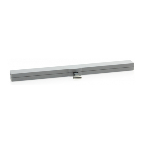
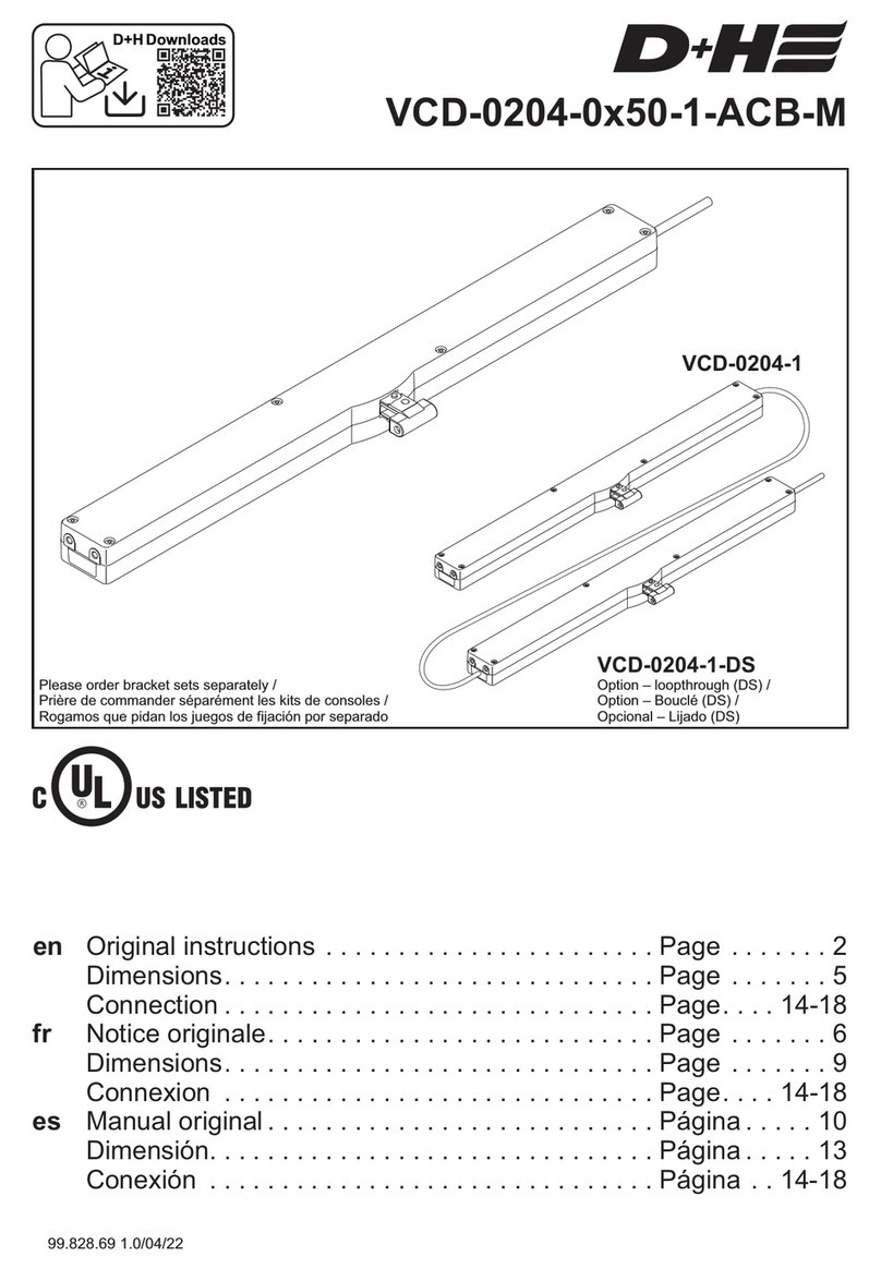
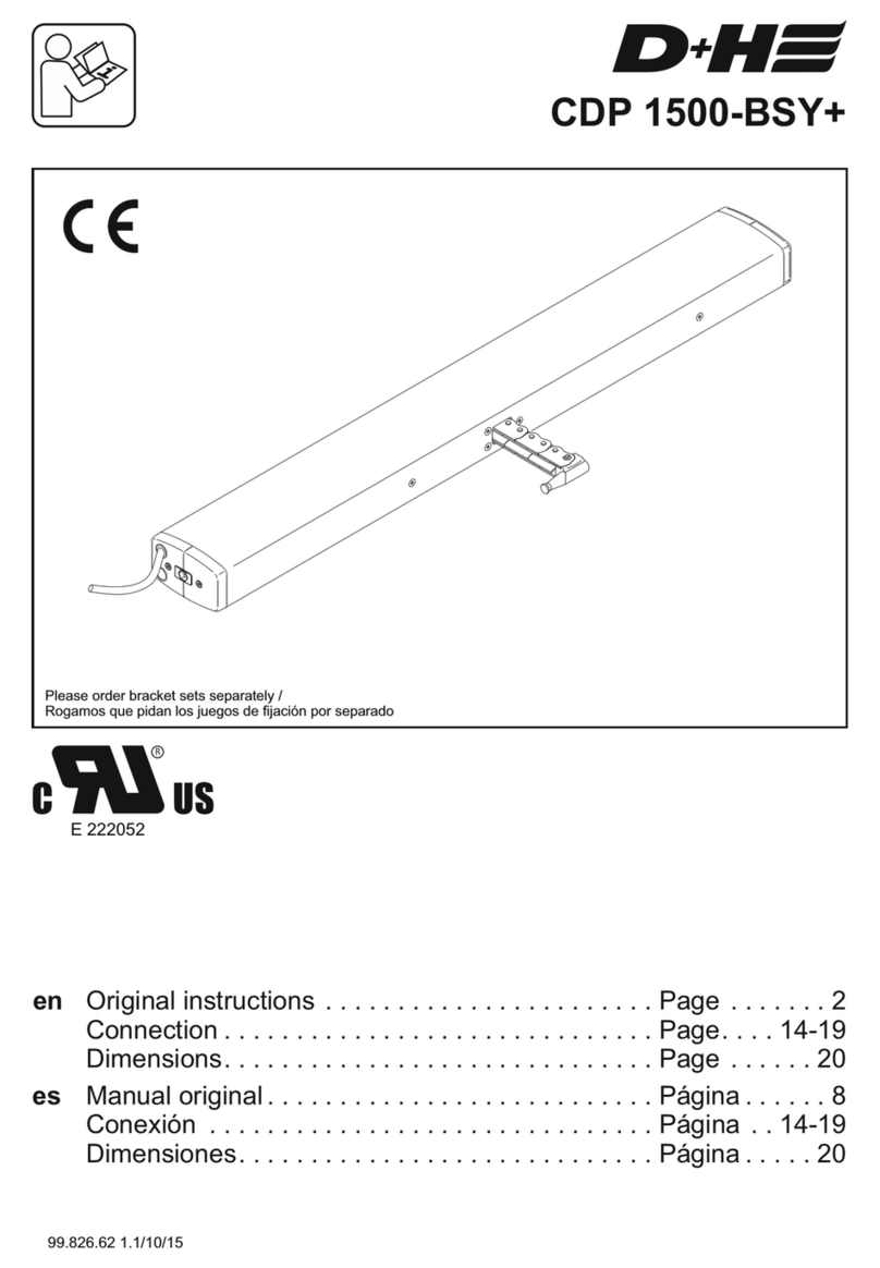
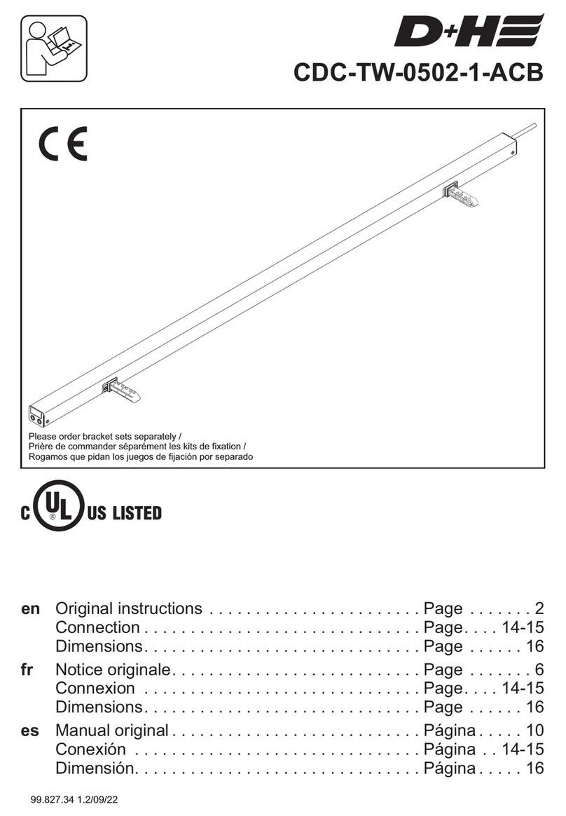
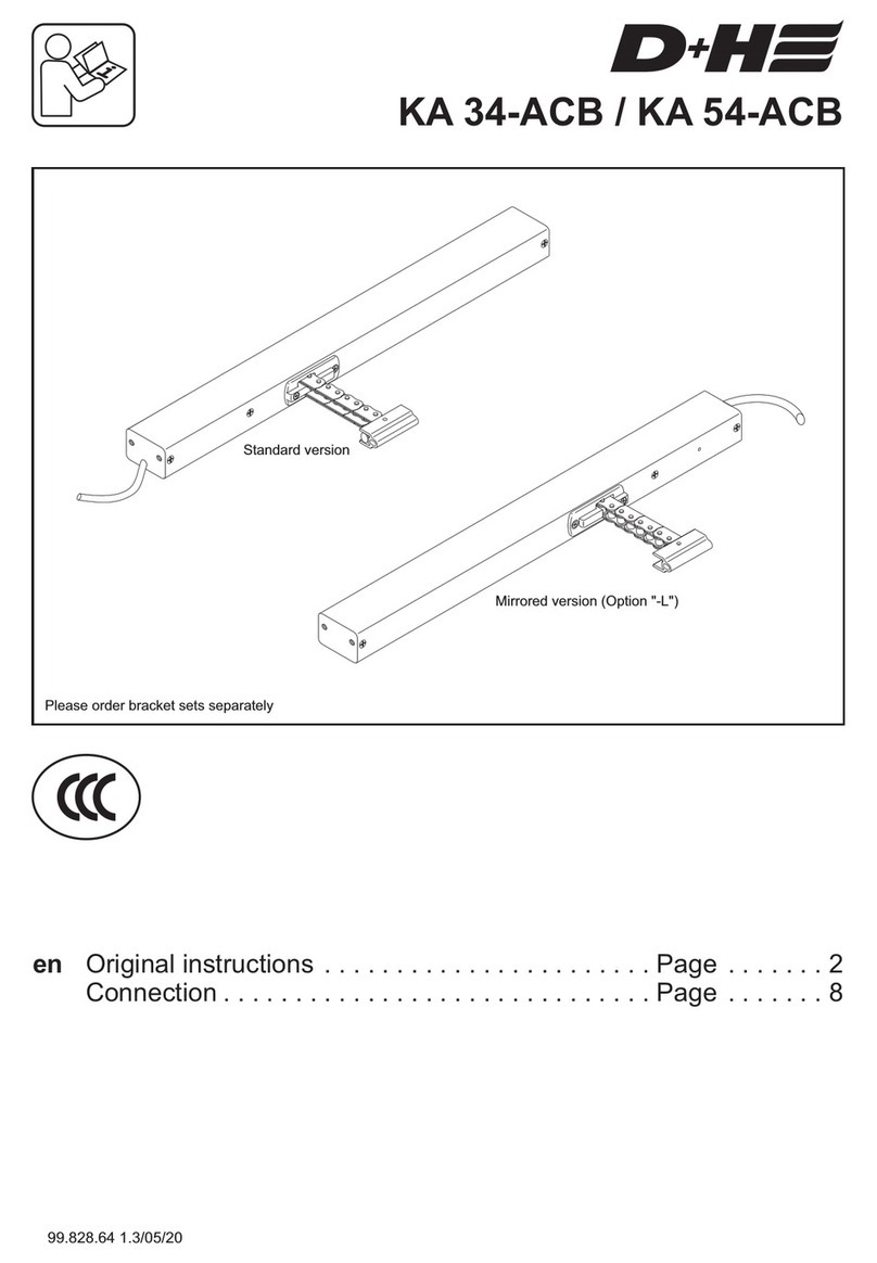
D+H ZA 35-K-BSY+ User manual

de
en
fi
es
Originalbetriebsanleitung . . . . . . . . . . . . . . . . . . . Seite . . . . . . . 2
Original instructions . . . . . . . . . . . . . . . . . . . . . . . Page . . . . . . . 6
Käyttöohje . . . . . . . . . . . . .. . . . . . . . . . . . . . . . . . . Sivu . . . . . . . 10
Manual original . . . . . . . . . . . . . . . . . . . . . . . . . . . . Página . . . . . 14
ZA 35/85/105/155-K-BSY+(-HS)
Konsolensätze bitte separat bestellen /
please order bracket sets separately /
Kiinnikesarjat tilattava erikseen. /
Rogamos que pidan los juegos de fijación por separado
Standard Ausführung /
Standard version /
Vakio malli /
Estándar modelo
Ausführung ohne Tubus
Version without tube
versio ilman suojaputkea (option "-OT") /
Modelo sin tubo (opcional "-OT")
(Option "-OT") /
(option "-OT") /
99.823.99 1.1/07/11

Deutsch
ZA-K-BSY+
99.823.99 1.1/07/11
2/20
- Der Schwenkraum desAntriebes muss über den
gesamten Hubbereich frei gehen.Anderenfalls
kann die Zahnstange undAufhängung beschädigt
werden.
- Antriebe mit einem Hub 800 mm nicht „unten
aufgehängt“ montieren (z.B. Konsole UK).
- Augenschraube so einstellen, dass derAntrieb bei
geschlossener Klappe über seine innere Endla-
gendämpfung abschaltet. Bei zu fester Ein-
stellung können die Konsolen beschädigt werden!
- DasAntriebsset ist vom Werk aus eingestellt. Bei
Veränderungen des Auslieferzustandes (wie z. B.
Antriebe aus bestehendem Set herausnehmen
bzw. neu eingliedern) müssen dieAntriebe mit
SW-BSY+ neu programmiert werden.
- NurAntriebe mit gleicher Kraft verwenden.
- Gleichmäßige Lastverteilung auf alleAntriebe
beachten.
Montagehinweise
Antriebseinheit mit 2,5 m Silicon-Kabel. Abhängig
vom Fenstertyp sind verschiedene Konsolensätze
separat erhältlich.
Lieferumfang
Die maximale Drucklast der Zahnstange entspricht
nicht automatisch der maximalen Druckkraft des
Antriebes!
Lasten von über 1000 N bis zu 1500 N sind nur
kurzzeitig zulässig (z. B. zum Schneeabwerfen oder
bei Windbelastungen). Diese dürfen bis zu einem
Hub von 800 mm auftreten.
Drucklast-Diagramm
500
600
800
1000
1100
1200
1300
1400
1500
1600
0
200
400
600
800
1000
1200
1400
max. Last (N)
Hub (mm)
dauerhaft
kurzzeitig
Sicherheitshinweise
Betriebsspannung 230 VAC!
Verletzungsgefahr durch Stromschlag!
L+N nicht vertauschen! PE anschließen!
230V liegen auch am BSY+ Datenbus an!
- Anschluss darf nur durch eine autorisierte
Elektrofachkraft erfolgen.
- Quetschgefahr im handzugänglichen Bereich.
- Personen aus dem Fahrbereich desAntriebes
fernhalten.
- Kinder von der Steuerung fernhalten.
- Nur in trockenen Räumen verwenden.
- Nur für die Innenmontage geeignet.
Bei Gefahr durch Regen (z.B. an Lichtkuppel oder
Dachflächenfenster) Regenmelder verwenden.
- Nur unveränderte D+H-Originalteile verwenden.
- Montageanleitung des Konsolensatzes beachten.
- Drucklast-Diagramm der Zahnstange beachten!
- BeiAußenmontage Option “ -W “ einsetzen!
Beiliegenden roten Sicherheitszettel beachten!
* nur mit BI-BT1 (Galvanische Trennung durch Bluetooth)
- Zahnstangenantrieb zum elektromotorischen
Öffnen und Schließen von Fenstern und Klappen
im Fassaden- und Dachbereich
- Betriebsspannung 230 VAC
- Für bis zu 4Antriebe geeignet
- Einsetzbar für Öffnungen zur Rauchableitung,
D+H Euro-RWAgemäß DIN EN 12101-2 sowie für
täglichen Lüftungsbetrieb
- Nur für die Innenmontage geeignet
Bestimmungsgemäße Verwendung
- Mikroprozessorgesteuerte Synchro-Elektronik
BSY+ für sicheren und präzisen Synchronlauf
von bis zu 4Antrieben
- Individuell programmierbar über Software
SW-BSY+*
- RWA-Highspeed-Funktion (Schnelllauf inAUF-
Richtung)
- Schließkantenschutz für die Hauptschließkante
- Besonders leise im Lüftungsbetrieb durch
reduzierte Motordrehzahl
- Optional mit "-AS2" = Schutzklasse 2 und
"-AS3" sowie "-LS" = Schutzklasse 3
Leistungsmerkmale

Typ
Versorgung 230 VAC, ±10% 230 VAC, ±10% 230 VAC, ±10% 230 VAC, ±10%
Wirkleistung 20 W (35 W) 30W (50 W) 35 W (60 W) 45 W (75 W)
Scheinleistung 30 VA(45 VA) 45 VA(75 VA) 55 VA(85 VA) 70 VA(105 VA)
Nenn-Kraft 300 N 800 N 1000 N 1500 N
Nenn-Verriegelungskraft 1100 N
Lebensdauer >10 000 Doppelhübe
Einschaltdauer 30 %, bei Spielzeit 10 Minuten
Gehäuse Aluminium eloxiert, PC
Schutzart IP 65
Temp. Bereich -5 ... +75°C
Temp. Standsicherheit 30 min / 300°C
Nenn-Hublänge * siehe Typenschild
Zusatzfunktionen * Schließkantenschutz aktiviert (3 Wiederholungshübe)
* Programmierbar mit Software SW-BSY+ und BI-BT1 via Bluetooth
ZA35-K-BSY+(-HS) ZA85-K-BSY+(-HS) ZA105-K-BSY+(-HS) ZA155-K-BSY+(-HS)
Laufgeschwindigkeiten und Kräfte
Normalbetrieb =
RWA- Schnelllauf =
Alle Kräfte
+ ca. 20 % Abschaltreserve
(kurzzeitig)
AUF
Kräfte
SB III
SB II
SB I
300 N
300 N
300 N
300 N
800 N
800 N
800 N
800 N
1000 N
1000 N
1000 N
800 N
1500 N
1000 N
1000 N
800 N
ZA 35 ZA 85 ZA 105 ZA 155
I III
77mm
23mm
7,1 mm/s
5 mm/s5 mm/s
~7,1 mm/s / ~9 mm/s (-HS: ~17 mm/s)
II
Schließbereiche
Technische Daten
ZU
Deutsch
ZA-K-BSY+
99.823.99 1.1/07/11
3/20
Schließkantenschutz
In Laufrichtung "ZU" verfügt der Antrieb über einen
aktiven Schutz für die Hauptschließkante. Bei einer
Überlast im Schließbereich 3 und 2 fährt der Antrieb
für 10 Sekunden wieder "AUF". Danach fährt der
Antrieb wieder "ZU". Sollte nach drei Versuchen ein
Einfahren nicht möglich sein, bleibt der Antrieb in
dieser Stellung stehen.
Zusätzlich verfügt der Antrieb über einen passiven
Klemmschutz. Die Schließgeschwindigkeit wird im
Schließbereich 2 und 1 auf 5 mm/s reduziert.
An den Nebenschließkanten können
deutlich höhere Kräfte auftreten.
Quetschgefahr im handzugänglichen
Bereich.
Hauptschließkante
Nebenschließkante
Nebenschließkante

Deutsch
ZA-K-BSY+
99.823.99 1.1/07/11
4/20
Aderbelegung Stecker
Anschluss: Seite 18 - 19
*wird auf L-ZU und L-AUF
gleichzeitig Strom gelegt
fährt derAntrieb in HS
Einbaubeispiele
Dreieckspyramide*
Lichtkuppel Pyramide*
schwerer
Fensterflügel
Unkritische Lastverteilung Kritische Lastverteilung
* Bei kompletten Anheben der Pyramide/Lichtkuppel ist wegen der zu erwartenden seitlichen
Windlast eine bauseitige Führung notwendig!
YE/GN (PE)
zweites Anschlusskabel
WH (n.c.)
GY (n.c.)
YE (+SGI)
GN (-SGI)
zweites Anschlusskabel
GN (SZ)
GY (SZ)
YE (SA)
WH (SA)
Option -SZ-SA
GN (Data B)
YE (Data A)
BN (L - ZU)*
BK (L - AUF)*
BU (N)
230 VAC
Option -SGI
GN (Data B)
YE (Data A)
BN (L - ZU)*
BK (L - AUF)*
BU (N)
230 VAC
230 VAC
Standard
GN (Data B)
YE (Data A)
BN (L - ZU)*
BK (L - AUF)*
BU (N)

Deutsch
ZA-K-BSY+
99.823.99 1.1/07/11
5/20
Konformitätserklärung
Wartung und Reinigung
Die Inspektion und Wartung hat gemäß den D+H-
Wartungshinweisen zu erfolgen. Es dürfen nur
original D+H-Ersatzteile verwendet werden. Eine
Instandsetzung erfolgt ausschließlich durch D+H.
Wischen Sie Verschmutzungen mit einem trock-
enen, weichen Tuch ab.
Verwenden Sie keine Reinigungs- oder Lösemittel.
Garantie
Auf alle D+H-Artikel erhalten Sie Garantie
ab belegter Übergabe der Anlage bis max. 3 Jahre
nach Auslieferungsdatum, wenn die Montage bzw.
Inbetriebnahme durch einen von D+H autorisierten
durchgeführt
wurde.
Bei Anschluss von D+H-Komponenten an
Fremdanlagen oder Vermischung von D+H-
Produkten mit Teilen anderer Hersteller erlischt die
D+H-Garantie.
2 Jahre
Service- und Vertriebspartner
Wir erklären in alleiniger Verantwortung, dass das
unter „Technische Daten“ beschriebene Produkt mit
den folgenden Richtlinien übereinstimmt:
2004/108/EG, 2006/95/EG
Technische Unterlagen bei:
D+H MechatronicAG, D-22949Ammersbek
Thomas Kern Maik Schmees
Vorstand Prokurist, Technischer Leiter
12.10.2009
Elektrogeräte, Zubehör und Verpackungen sollen
einer umweltgerechten Wiederverwertung zugeführt
werden.
Werfen Sie Elektrogeräte nicht in den
Hausmüll!
Nur für EU-Länder:
Gemäß der Europäischen Richtlinie
2002/96/EG über Elektro- und
Elektronik-Altgeräte und ihrer
Umsetzung in nationales Recht müssen nicht mehr
gebrauchsfähige Elektrogeräte getrennt gesammelt
und einer umweltgerechten Wiederverwertung
zugeführt werden.
Entsorgung
Eine ZA-K-BSY+ (-HS) Synchrongruppe kann aus
bis zu 4 Antrieben bestehen, welche über einen Bus
kommunizieren. Jeder Antrieb hat seine eigene
Adresse. Diese ist mittels Software SW-BSY+ und
BI-BT1 konfigurierbar. Der letzte Antrieb einer
Synchrongruppe ist der Master, welcher die
restlichen Antriebe, die Slaves, steuert. Kraftdiffer-
enzen zwischen den Antrieben einer Synchron-
gruppe werden durch eine intelligente Kraft- und
Positionsregelung ausgeglichen. Bei Störung bzw.
Ausfall eines Antriebes werden alle Antriebe
automatisch abgeschaltet.
Funktionsbeschreibung
Sichtprüfung:
Verdrahtung:
Nullabgleich:
D+H Service anrufen:
Es darf nur ein MasterAntrieb vorhanden sein.
Der Master hat, entsprechend derAnzahl der
gesamtAntriebe, die letzteAdresse.
DieAdresse ist auf denAntrieb aufgeklebt.
SlaveAntriebe sind abwärts durchnummeriert.
Bsp.: In einer Gruppe, bestehend aus 3Antrieben,
gibt es einen Master 3, einen Slave 2 und einen
Slave 1Antrieb.
Achtung: gilt nur beiAuslieferzustand. Sobald die
Antriebe mittels SW-BSY+ neu konfiguriert wur-
den gilt die werksseitigeAdressierung nicht mehr!
Ist die Gruppe ordnungsgemäß verdrahtet?
Siehe dazuAnschlusspläne
Nullabgleich durchführen.
Software SW-BSY+ mit BI-BT1 oder spezieller
Magnet MAG 502 wird benötigt.
Konfigurierung derAntriebe erforderlich.
Die Software SW-BSY+ und BI-BT1 inkl.
Verbindungskabel (30.006.23) wird benötigt.
Störungssuche

English
ZA-K-BSY+
99.823.99 1.1/07/11
6/20
500
600
800
1000
1100
1200
1300
1400
1500
1600
0
200
400
600
800
1000
1200
1400
max. Load (N)
Stroke (mm)
durable
temporary
Drive unit with 2.5 m silicone cable. Depending on
the type of window, different bracket sets are
available separately.
Scope of supply
Mounting information
Pressure load diagram
Safety notes
Operating voltage 230 VAC!
Risk of injury from electric shock!
Do not reverse L+N! Connect PE!
The BSY+ bus also operates with 230V!
Observe enclosed red safety note!
- Connection must be carried out by a certified
electrical technician
- Danger of crushing hands and fingers!
- Keep people away from the operating area of
the drive
- Keep children away from the control
- Observe pressure load diagram of the gear rack!
- Use only in dry rooms
- Suitable for indoor mounting only. Use rain
detector in the event that there is a risk of rain
- Use option "-W" if mounted outdoors!
- Use unmodified original D+H parts only
- Observe the bracket-set mounting instructions
* only with BI-BT1 (electronically isolated due to Bluetooth)
- Rack and pinion drive for electric opening and
closing of windows and flaps in the facade and
roof area
- Operating voltage 230 VAC
- Up to 4 drives possible
- Useable for smoke extraction, D+H Euro-SHEV in
accordance with DIN EN 12101-2 as well as daily
ventilation
- Suitable for indoor mounting only
Intended use
- Microprocessor-controlled synchronous
electronics BSY+ for safe and precise
synchronous running of up to 4 drives
- Individually programmable via software SW-BSY+*
- SHEV-high speed function (fast-running feature in
OPEN-direction)
- Closing edge protection for the main closing edge
- Especially quiet motor running in ventilation mode
- Optinal with "-AS2" = protection class 2 and
"-AS3" as well as "-LS" = protection class 3
Features
- Swivel radius of the drive must go free over entire
range of stroke. Otherwise, the toothed rack and
the suspension can be damaged.
- Drives with a stroke of must not be moun-
ted „hung up at the bottom“ (e.g. bracket UK).
- Eyebolt has to be adjusted so, that the drive is
disconnected with closed flap through it’s inside
stop position damping. Brackets can be damaged
by to rigid adjustment!
800 mm
- The drive set will be full configured by factory.
The drives must be reconfigured in case of
alterations (e.g. removing of drives from existing
set or integrating a new drive) with SW-BSY+*.
- Use only drives with the same force.
- Ensure evenly load distribution on all the drives.
Maximum pressure load of the toothed rack is not
automatically identical with maximum pressure force
of the drive!
Loads from over 1000 N to 1500 N are only briefly
permissible (e.g. to throwing off snow or with wind
loads). These may arise up to a stroke of 800 mm.

English
ZA-K-BSY+
99.823.99 1.1/07/11
7/20
Type
Supply 230 VAC, ±10% 230 VAC, ±10% 230 VAC, ±10% 230 VAC, ±10%
Active power 20 W (35 W) 30W (50 W) 35 W (60 W) 45 W (75 W)
Apparent output 30 VA(45 VA) 45 VA(75 VA) 55 VA(85 VA) 70 VA(105 VA)
Nominal force 300 N 800 N 1000 N 1500 N
Nominal locking force 1100 N
Service life >10 000 double strokes
Duty cycle 30 %, with cycle time 10 minutes
Housing aluminium anodized / polycarbonate
Ingress protection IP 65
Temperature range -5 ... +75°C
Fire stability 30 min / 300°C
Nominal stroke length * see type plate
Additional functions * Closing edge protection activated (3 stroke repeatings)
* programmable with software SW-BSY+ and BI-BT1 via Bluetooth
ZA35-K-BSY+(-HS) ZA85-K-BSY+(-HS) ZA105-K-BSY+(-HS) ZA155-K-BSY+(-HS)
All forces + approx.
20% cut-off reserve
(temporary)
OPEN
Forces
CR III
CR II
CR I
300 N
300 N
300 N
300 N
800 N
800 N
800 N
800 N
1000 N
1000 N
1000 N
800 N
1500 N
1000 N
1000 N
800 N
ZA 35 ZA 85 ZA 105 ZA 155
I III
77mm
23mm
7,1 mm/s
5 mm/s5 mm/s
II
Closing ranges
Technical data
CLOSE
Closing edge protection
In the "CLOSE" direction the drive has an active
protection for the main closing edge. If there is an
overload in the closing range 3 and 2, the drive runs
"OPEN" for 10 seconds, then "CLOSE" again. If after
three attempts closing is not possible, the drive
remains in this position.
In addition, the drive is equipped with passive pinch
protection. The closing speed in closing range 2 and
1 is reduced to 5 mm/s.
Significantly greater forces can be
exerted at the secondary closing
edges. Danger of crushing hands and
fingers!
main closing edge
beside closing edge
beside closing edge
Normal operation =
fast-mode SHEV =
Running speeds and forces
~7,1 mm/s / ~9 mm/s (-HS: ~17 mm/s)

English
ZA-K-BSY+
99.823.99 1.1/07/11
8/20
Pin Assignment
Connection: Page 18 - 19
*if power is set on L-CLOSE
and L-OPEN simultaneously,
the drive opens in HS
YE/GN (PE)
second connecting cable
GN (SZ)
GY (SZ)
YE (SA)
WH (SA)
second connecting cable
WH (n.c.)
GY (n.c.)
YE (+SGI)
GN (-SGI)
Option -SZ-SA
GN (Data B)
YE (Data A)
BN (L - CLOSE)*
BK (L - OPEN)*
BU (N)
230 VAC
Option -SGI
GN (Data B)
YE (Data A)
BN (L - CLOSE)*
BK (L - OPEN)*
BU (N)
230 VAC
230 VAC
Standard
GN (Data B)
YE (Data A)
BN (L - CLOSE)*
BK (L - OPEN)*
BU (N)
Mounting examples
triangular pyramid *
domelight pyramid * weighty wing
Uncritical load distribution Critical load distribution
* Guiding device required by customer in case of complete lift-off of pyramid/domelight,
because of possible lateral load due to wind pressure!

English
ZA-K-BSY+
99.823.99 1.1/07/11
9/20
Visual inspection:
Wiring:
Adjustment of zero point:
Call D+H Service:
Only one master-drive allowed.
The master has, according to common drives,
the last adress.
The adress is sticked on the drive. Slaves are
nubered downwards.
Example: In a group, composed of 3 drives,
there is a master 3, a slave 2 and a slave 1drive.
Attention: only applies by factory set. as soon as
the drives were reprogramized with SW-BSY+
he factory set adressing does not apply any
longer.
Is the group wired correctly? Please refer to the
connection diagrams in this regard
Adjust the zero point.
Software SW-BSY+ with BI-BT1 or the
special magnet MAG 502 is required
Drives must be configured.
Software SW-BSY+ and BI-BT1 incl. connection
cable (30.006.23) is required
Troubleshooting
A synchronous group ZA-K-BSY+ (-HS) can contain
up to 4 drives, which communicate via bus. Each
drive has its own address, configurable with SW-
BSY+ and BI-BT1. The last drive of a synchronous
group is the master, which controls the other drives,
the slaves. Differences in forces between the drives
of a group are balanced by means of intelligent force
and position control. In the event that a drive
malfunctions, all the drives are automatically cut off.
Functional description
Declaration of Conformity
We declare under our sole responsibility that the
product described under “Technical Data” is in
conformity with the following directives:
2004/108/EC, 2006/95/EC
Technical file at:
D+H MechatronicAG, D-22949Ammersbek
Thomas Kern Maik Schmees
Member of the Board Authorized signatory, Technical Director
12.06.2010
Electrical devices, accessories and packaging
should be sorted for environmental-friendly recycling.
Do not dispose electrical
devices into household waste!
Only for EC countries:
According the European Guideline
2002/96/EC for waste electrical and
electronic equipment and its implemen-
tation into national right, electrcal
devices that are no longer usable must be collected
separately and disposed of in an environmentally
correct manner.
Disposal
Maintenance and cleaning
Inspection and maintenance has to be carried out
according to D+H maintenance notes. Only original
D+H spare parts may be used. Repair is to be carried
out exclusively by D+H.
Wipe away debris or contamination with a dry, soft
cloth.
Do not use cleaning agents or solvents.
Guarantee
You will get for all D+H products
from date of verified handing over of the system up to
maximal 3 years after date of delivery, when
mounting and starting has been carried out by
D+H guarantee is expired, with connection of D+H
components with external systems or with mixing of
D+H products with parts of other manufacturers.
2 years guarantee
an
authorized D+H-distributor.

Suomi
ZA-K-BSY+
99.823.99 1.1/07/11
10/20
Hammastangon maksimi kuormitus ei ole automaattisesti
sama kuin moottorin maksimi kuormitus.
Kuormat 1000-1500Novat sallittuja vain lyhytaikaisesti
(esim. lumikuorman poisto tai tuulikuorman kumoaminen).
Tällaista voi ilmetä aina 800mm likemittaan asti.
500
600
800
1000
1100
1200
1300
1400
1500
1600
0
200
400
600
800
1000
1200
1400
voima max. (N)
liikemitta (mm)
jatkuva
hetkellinen
Kuormitustaulukko
*Vain BI-BT1:n kanssa (Sähköinen erotus Bluetoothin välityksellä)
-Hammastankoavaaja seinä-ja kattoluukkujen
sähköiseen avaamiseen ja sulkemiseen
-Toimintajännite 230 VAC
-Max. 4 avaajaa mahdollisuus kytkeä yhteen
-Soveltuu savunpoistoon,DIN EN 12101-2 mukaisesti,
kuten myös päivittäistuuletukseen.
-Soveltuu vain sisäasennukseen,EI ulkokäyttöön.
Käyttötarkoitus
Avaajalaite jossa 2,5msilikonikaapeli.
Useita eri kiinnikesarjoja saatavilla eri tyyppisiin
rakenteisiin. Kiinnikesarjat tilattava erikseen.
Toimitussisältö
Ominaisuudet
-Mikroprosessori ohjattu synkroinointi elektroniikka
tarkkaan ja turvalliseen hallintaan max. 4:lle
avaajalle
- Yksilöllisesti ohjelmoitavissa SW BSY+* ohjel -
malla
- -HS toiminto nopeaan avaukseen savunpois-
totilanteessa
-‘sormisuoja’ ominaisuus sulkeutumisjaksolla
- Erittäin hiljainen moottori tuuletuskäytössä
- Saatavissa myös “-AS 2”= suojausluokka 2,
sekä “-AS3” kuten “-LS”= suojausluokka 3
Turvallisuusohjeita
Käyttöjännite 230 VAC!
Sähköiskun vaara! Älä vaihda L ja N paikko-
ja! Kytke PE!
BSY+ väylä toimii myös 230V jännitteellä!
Noudata avaajaan liitettyä punaista turvaohjetta!
-Kytkennän saa suorittaa vain asianmukaisen
koulutuksen saanut sähkömies
- Puristumisvaara
- Ihmisten pysyttävä poissa avaajan toiminta-
alueelta
- Lapset pidettävä poissa asennuspaikalta
- Huomio tankoon kohdistuva kuormitus
- Käyttö vain kuivissa tiloissa
- Vain sisäasennukseen. Sadetunnistinta
tulee käyttää mikäli on riski avaajan altis-
tumiselle sateelle
- Käytä optiolla -W varustetua avaajaa mikä
li avaaja asennetaan ulkotilaan
- Käytä vain alkuperäisiä D+H varaosia
- Noudata kiinnikkeiden asennusohjeita
- Avaajan kääntösäteen tulee olla vapaa koko liikemitan
matkalta. Muutoin hammastanko tai tuenta voi vauri-
oitua.
- Avaajat joissa liikemitta 800mm tai suurempi,ei tulisi
asentaa “häntäpään”kiinnityksellä (esim. kiinnike UK).
- Avaaja kokonaisuudet konfiguroidaan tehtaalla. Avaa-
jat tulee konfiguroida uudelleen mikäli kokoonpanoa
muutetaan (esim. vanha avaaja vaihdetaan uuteen)
SW BSY+* ohjelmistolla
-Käytä vain saman voimaisia avaajia pareina.
- Varmista avaajille tasainen kuormitus
-Silmukka ruuvi tulee säätää niin,että ikkunan ollessa
täysin kiinni,avaaja on täysin sisään ajaneessa tilassa.
Muutoin kiinnikkeet voivat vaurioitua.
Asennusohjeita

Suomi
ZA-K-BSY+
99.823.99 1.1/07/11
11/20
Normaali toiminta =
Nopea -HS toiminto =
Type
Syöttöjännite 230 VAC, ±10% 230 VAC, ±10% 230 VAC, ±10% 230 VAC, ±10%
Tehonkulutus 20 W (35 W) 30W (50 W) 35 W (60 W) 45 W (75 W)
Näennäisteho 30 VA (45 VA) 45 VA (75 VA) 55 VA (85 VA) 70 VA (105 VA)
Nimellisvoima300 N 800 N 1000 N 1500 N
1100 N
Kestoikä>10 000 auki- kiinni kertaa
Käyttöaste 30%,10 minuutin käyttösyklillä
Kotelo anodisoitu alumiini /polykarbonaatti
SuojausluokkaIP 65
Käyttö lämpötila -5 ... +75°C
Palonkesto 30 min / 300°C
Nimellis liikepituus *Kts. tyyppikilpi
Lisätoiminnor *Sormisuoja konedirektiivin mukaisesti (3toistokertaa)
*Ohjelmoitavissa SW-BSY+ ohjelmiston ja BI-BT1Bluetoothin kanssa
ZA35-K-BSY+(-HS) ZA85-K-BSY+(-HS) ZA105-K-BSY+(-HS) ZA155-K-BSY+(-HS)
Lukitusvoima
Voimat
PF III
PF II
PF I
300 N
300 N
300 N
300 N
800 N
800 N
800 N
800 N
1000 N
1000 N
1000 N
800 N
1500 N
1000 N
1000 N
800 N
ZA 35 ZA 85 ZA 105 ZA 155
IIII
77mm
23mm
7,1 mm/s
5 mm/s
5mm/s
II
s
ulkeutumisalueet
Tekniset tiedot
Sormisuojaus
KIINNI suunnassa moottori on varustettu aktiivisella
sulkeutuvan reunan suojauksella. Mikäli suljettaessa tapahtuu
ylikuormitus tilanne alueilla 3 ja 2, ajaa avaaja itseään AUKI
10s. ja yrittää uudelleen sulkutoimintoa. Mikäli avaaja ei kol-
mella yrittämällä onnistu sulkemaan itseään, se pysähtyy.
Lisäksi avaaja on varustettu passiivisella puristumisen esto
suojauksella. Sulkeutumis nopeus alennetaan alueilla 2 ja 1
nopeuteen 5mm/s.
Saranapuolella voi esiintyä huomattavasti
suurempia puristusvoimia, joten sillä osalla
on puristumisvaara suuri! Sormia ei tule
työntää saranan puoleiselle sivulle luukun
sulkeutuessa!
sulkeutuva reuna
suleutuvan reunansivu
A
vautumis nopeudet ja voimat
Kaikki voimat +20%,
tilapäisesti korotettavissa.
AUKI
KIINNI
~7,1 mm/s /~9 mm/s (-HS: ~17 mm/s)

Suomi
ZA-K-BSY+
99.823.99 1.1/07/11
12/20
Kytkentäliittimet
Kytkentä: sivu 18 - 19
*Jos jännite syötetään yhtä
aikaa AUKI-ja KIINNI
suuntaan,avautuu avaaja
-HS toiminnolla nopeasti
KE/VI (PE)
Toinen kytkentäkaapeli
VIHR.(SZ)
HARM. (SZ)
KELT.(SA)
VALK. (SA)
Toinen kytkentäkaapeli
VALK. (n.c.)
HARM. (n.c.)
KELT. (+-SGI)
VIHR. (-SGI)
Optiot -SZ-SA
VIHREÄ(Data B)
KELTAINEN (Data A)
RUSKEA (L - KIINNI)*
MUSTA (L - AUKI)*
SININEN (N)
230 VAC
Optio -SGI
VIHREÄ(Data B)
KELTAINEN (Data A)
RUSKEA (L - KIINNI)*
MUSTA (L - AUKI)*
SININEN (N)
230 VAC
230 VAC
Vakio
VIHREÄ(Data B)
KELTAINEN (Data A)
RUSKEA (L - KIINNI)*
MUSTA (L - AUKI)*
SININEN (N)
Asennus esimerkkejä
Kolmio pyramidi*
KattovalokupuPyramidi*Raskas ikkuna
Vähemmän kriittinen painonjako Kriittinen painonjako
*Ohjainputki tulee asentaa mikäli pyramidi/kattokupu nostetaan kokonaisuudessaan ilmaan,koska suuria
vaakasuuntaisia voimia voi esiintyä esim. tuulikuorman johdosta!

Suomi
ZA-K-BSY+
99.823.99 1.1/07/11
13/20
Synkronoitu ryhmä ZA-K-BSY+ (-HS)voi sisältää max. 4
moottoria, jotka kommunikoivat väylän välityksellä.Jo-
kaisella moottorilla on on osoitteensa, jota voi muokata
SW-BSY+ ohjelmistolla BI-BT1 bluetooth yksikön välityk-
sellä. Viimeinen moottori synkroniryhmässä on aina
master, joka ohjaa muita avaajia (Slave). Ryhmän sisällä
olevien moottoreiden voimaerot tasoitetaan älykkäällä
voiman ja asennon ohjauksella. Mikäli avaajaryhmässä yk-
sikin moottori vikaantuu, pysähtyvät kaikki synkroniryh-
män moottorit automaattisesti.
Toimintakuvaus
Sähkölaitteet,tarvikkeet ja pakkausmateriaalit tulee
lajitella ympäristöystävällistä kierrätystä varten.
Älä hävitä sähkölaitteita kaatopaikkajätteen mu-
kana!
Vain EU maat:
Eurooppaneuvoston ohjeistuksen
2002/96/CE sähkö- ja elektroniikkajätteel-
le sanoo seuraavaa.
Käyttökelvottomat sähkö- ja elektroniik-
kalaitteet tulee purkaa ja erotella, sekä
toimittaa asianmukaisesti kierrätettäväksi.
Vakuutamme,että myymämme tuotteen tekniset
tiedot vastaavat seuraavan direktiivin vaatimuksia:
2004/108/EG,2006/95/CE
Mittauspöytäkirjan sijainti
D+HMechatronic AG,D-22949Ammersbek
Thomas Kern Maik Schmees
Hallituksen jäsen valtuutettu allekirjoittaja,tekninen johtaja
12.06.2010
Vaatimuksenmukaisuus Hävittäminen
Tarkastukset ja huollot tulee suorittaa D+H:n
huoltoohjeiden mukaisesti. Korjauksissa saa käyttää vain
alkuperäisiä D+Hvaraosia. Fyysiset korjaukset saa
suorittaa vain D+Htai valtuutettu maahantuoja.
Puhdista lika pyyhkimällä kuivalla ja pehmeällä liinalla.
Älä käytä pesuainetta tai liuotusainetta puhistukseen.
Huolto ja puhdistus
Kaikille D+H tuotteille myönnetään 2:den vuoden
takuu vahvistetusta luovutuspäivästä lukien., sekä
maksimissaan 3 vuotta toimituspäivästä, kun asen-
nuksen ja käyttöönoton on suorittanut D+H:n val-
tuuttama asennus- / huoltoliike.
D+H takuu raukeaa, jos D+H tuotteita liitetään ul-
kopuolisiin järjestelmiin tai sekoitetaan D+H tuottei-
ta muiden valmistajien tuotteisiin.
Takuu
Vianhaku
Silmämääräinen tarkastus:
Kaapelointi :
Nollakohdan asetus:
Soita D+Hhuoltoon kun:
Vain yksi master avaaja sallitaan.
Master avaajassa tulee aina olla viimeinen
osoitenumero.
Osoite on merkattu tarralla avaajaan. Slave avaajat
on numeroitu alenevasti.
Esimerkki: Ryhmässä, jossa 3 moottoria, siellä master
on nro 3, slave 2 ja slave 1.Huom. Tämä pätee vain
tehdasasetettuihin moottoreihin, mikäli avaajat ohjel-
moidaan uudelleen SW BSY+ ohjelmistolla, ei osoite
määrittely le enää voimassa.
Onko johdotukset tehty oikein? Tarkista kytken-
nät tähän ohjeen mukaisiksi.
Säädä nollapiste.
SW-BSY+ ohjelmisto ja BI-BT1 kaapeleineen
tai magneetti MAG 502 tarvitaan.
Avaajat pitää konfiguroida uudelleen.
SW-BSY+ ohjelmisto ja BI-BT1 kaapeleineen
(30.006.23)tarvitaan.

Español
ZA-K-BSY+
99.823.99 1.1/07/11
14/20
- El espacio de giro del accionamiento debe estar
libre en el rango completo de la carrera. De lo
contrario es posible que se dañe la cremallera y
la fijación
- Los accionamientos con una carrera de 800 mm
no se deben montar "colgados en la parte
inferior" (p.ej.,soporte UK)
- El juego de motores se ajustan de fábrica. En caso
de modificarse el suministro (como puede ser el
cambio de un motor por uno nuevo), los motores
deberán reprogramarse con el SW-BSY+*
- Únicamente deben utilizarse motores con la
misma fuerza
- Asegure una distribución uniforme de la carga en
todos los accionamientos
- El cáncamo se debe ajustar de tal manera que el
accionamiento se desconecte con la aleta cerrada a
través de su posición de parada interna de
amortiguación. Un ajuste demasiado rígido puede
dañar los elementos de fijación
≥
Instrucciones de montaje
Motor con 2,5 m de cable de silicona. Dependiendo
del tipo de apertura, pueden obtenerse por
separado, diferentes juegos de fijación.
Extensión de suministro
¡La carga de compresión máxima de la cremallera no
corresponde automáticamente a la fuerza de
compresión máxima del motor! Cargas superiores a los
1000 N y hasta los 1500 N solo son admisibles
provisionalmente (p. ej. para eliminar la nieve o en
casos de cargas por viento). Estas pueden darse con
una carrera máxima de hasta 800 mm.
Diagrama de carga de compresión
500
600
800
1000
1100
1200
1300
1400
1500
1600
0
200
400
600
800
1000
1200
1400
Carga máx. (N)
Carrera (mm)
* solo con BI-BT1 (aislado eléctricamente mediante Bluetooth)
- Accionamientos de cremallera para la apertura y
el cierre motorizado de ventanas y compuertas en
fachadas y techos
- Tensión de servicio 230 VAC
- Apropiado para un máximo de 4 motores
- Se puede utilizar en aperturas de extracción de
humos, D+H Euro-SVHC conforme a la norma
DIN EN 12101-2, así como para la ventilación
natural diaria
- Adecuado únicamente para el montaje interior
Utilización reglamentaria
Características
- Electrónica de sincronización controlada por
microprocesador BSY+ para un funcionamiento
sincronizado seguro y preciso de un máximo de 4
motores
- Programación individual mediante el software
SW-BSY+*
- Función de alta velocidad para SVHC (marcha
rápida en direcciónABRIR)
- Protección de cantos de cierre para el canto de
cierre principal
- Especialmente silencioso en el modo ventilación
- Opcionalmente con "-AS2" = clase de protección 2
y "-AS3" así como "-LS"= clase de protección 3
Notas de seguridad
¡Tensión de servicio 230 VAC!
Riesgos de lesiones por descarga eléctrica
¡No confundir L+N! ¡Conectar la puesta a tierra!
¡Respetar las indicaciones de la hoja de
serguridad adjunta!
230V estan tambien emplazado en BSY+ bus de
datos!
- La conexión deberá ser realizada únicamente por
un técnico electricista
- Peligro de aplastamiento en la zona accesible
a las manos
- Mantener a las personas alejadas del área de
trabajo del accionamiento
- Mantener alejados a los niños de los dispositivos
de control
- Usar solo en lugares secos
- Sólo es apropiado para el montaje interior.
En casos de peligro por lluvia, deberán utilizarse
sensores de lluvia
- ¡Utilizar la opción "-W" en caso de montaje
exterior!
- Emplear únicamente piezas originales D+H no
modificadas
- Observar las instrucciones de montaje del juego
de fijaciones
- ¡Observar el diagrama de carga de compresión de
la cremallera!
Permanente
temporalmente

Español
ZA-K-BSY+
99.823.99 1.1/07/11
15/20
Tipo
Alimentación 230 VAC, ±10% 230 VAC, ±10% 230 VAC, ±10% 230 VAC, ±10%
Potencia activa 20 W (35 W) 30W (50 W) 35 W (60 W) 45 W (75 W)
Potencia aparente 30 VA(45 VA) 45 VA(75 VA) 55 VA(85 VA) 70 VA(105 VA)
Fuerza nominal 300 N 800 N 1000 N 1500 N
Fuerza de bloqueo nominal 1100 N
Tiempo de vida >10 000 dobles carreras
Tiempo de funcionamiento 30 % (en ciclo de 10 minutos)
Carcasa aluminio, anodizado plateado / policarbonato
Protección IP 65
Temperatura -5 ... +75°C
Resistencia al fuego 30 min / 300°C
Carrera nominal * véase la placa de características
Funciones adicionales * Activada la protección del canto de cierre (tres carreras de repetición)
* programable con el software SW-BSY+ y BI-BT1 (Bluetooth)
ZA35-K-BSY+(-HS) ZA85-K-BSY+(-HS) ZA105-K-BSY+(-HS) ZA155-K-BSY+(-HS)
Todas las fuerzas
+ aprox. 20% de reserva
de desconexión (temporal)
ABRIR
Fuerzas
RCIII
RCII
RCI
300 N
300 N
300 N
300 N
800 N
800 N
800 N
800 N
1000 N
1000 N
1000 N
800 N
1500 N
1000 N
1000 N
800 N
ZA 35 ZA 85 ZA 105 ZA 155
I III
77mm
23mm
7,1 mm/s
5 mm/s5 mm/s
II
Rango de cierre
Datos técnicos
CIERRE
Protección en el borde al cerrar
En la dirección "CIERRE", el motor dispone de una
protección activa del canto principal de cierre. En caso de
darse una sobrecarga en el sector de cierre 3 y 2, el motor
parará y funcionará durante 10 segundos en dirección
opuesta. A continuación volverá a funcionar en dirección
"CIERRE". Si después de tres intentos no ha sido posible
cerrar, el motor se detendrá en esta posición.
Además, el motor dispone de una protección pasiva anti-
pinzamiento. La velocidad de cierre se reduce a 5 mm/s en el
rango de cierre 2 y 1.
En los cantos de cierre secundarios
pueden darse fuerzas considerablemente
más altas. Peligro de aplastamiento en el
área accesible para las manos.
Canto de cierre principal
Canto de cierre secundario
Canto de cierre secundario
Servicio normal =
marcha rápida SVHC =
Velocidades de funcionamiento y fuerzas
~7,1 mm/s / ~9 mm/s (-HS: ~17 mm/s)

Español
ZA-K-BSY+
99.823.99 1.1/07/11
16/20
Asignación de cables
Conexión: Página 18 - 19
*si el interruptor está situado en
L-CERRADO y L-ABIERTO
simultáneamente, el
accionamiento se abre en HS
YE/GN (PE)
segundo cable de conexión
GN (SZ)
GY (SZ)
YE (SA)
WH (SA)
segundo cable de conexión
WH (n.c.)
GY (n.c.)
YE (+SGI)
GN (-SGI)
Opcional -SZ-SA
GN (Data B)
YE (Data A)
BN (L - CIERRE)*
BK (L - ABRIR)*
BU (N)
230 VAC
Opcional -SGI
GN (Data B)
YE (Data A)
BN (L - CIERRE)*
BK (L - ABRIR)*
BU (N)
230 VAC
230 VAC
Estándar
GN (Data B)
YE (Data A)
BN (L - CIERRE)*
BK (L - ABRIR)*
BU (N)
Ejemplos de montaje
Pirámide triangular *
Claraboya Pirámide * Hoja de ventana pesada
Distribución de carga no crítica Distribución de carga crítica
* En caso de elevación completa de la pirámide/claraboya será necesario un guiado de seguridad por la
posible carga lateral de viento (a suministrar por el propietario).

Español
ZA-K-BSY+
99.823.99 1.1/07/11
17/20
Inspección visual:
Cableado:
Ajuste a cero:
Llamar al servicio de atención al cliente D+H:
Solo debe existir un accionamiento maestro. El
maestro tiene, en correspondencia con el
número total de accionamientos, la última
dirección. La dirección está indicada sobre el
accionamiento. Los accionamientos esclavos
están numerados en orden decreciente.
Ejemplo: en un grupo formado por tres
accionamientos existe un accionamiento
maestro 3, un accionamiento esclavo 2 y un
accionamiento esclavo 1. Atención: el juego de
accionamientos se ajusta de fábrica. En cuanto
se vuelvan a configurar los accionamientos con
el software SW-BSY+, las direcciones de fábrica
ya no serán válidas.
¿Es correcto el cableado del grupo? Para ello
deberá consultarse el diagrama de cableado
Realizar el ajuste a cero.
Se requiere el software SW-BSY+ con BI-BT1 o
el imán especial MAG 502.
Es necesario configurar los accionamientos.
Se requiere utilizar el software SW-BSY+ y BI
BT1, incluido el cable de conexión (30.006.23)
Solución de problemas
2 años de garantía para todos los productos D+H
desde la fecha de su puesta en marcha, hasta un
máximo de 3 años de la fecha de la entrega, siempre
que el montaje y la puesta en marcha hayan sido
realizados por un .
La garantía de D+H expira, en el caso de conexión
de componentes de D+H con otros equipos o
cuando se mezclan los productos de D+H con los de
otros fabricantes.
distributor autorizado de D+H
Declaramos bajo nuestra responsabilidad, que
el producto descrito bajo “Datos técnicos” está
en conformidad con las regulaciones:
2004/108/EG, 2006/95/EG
Expediente técnico en:
D+H MechatronicAG, D-22949Ammersbek
Thomas Kern Maik Schmees
Junta directiva Apoderado, Director técnicor
12.06.2010
Declaración de conformidad
Recomendamos que los aparatos eléctricos,
accesorios y embalajes sean sometidos a un
proceso de recuperación que respete el medio
ambiente.
¡No arroje las herramientas eléctricas a la basura!
Sólo para los países de la UE:
Conforme a la Directriz Europea
2002/96/CE sobre aparatos eléctricos
y electrónicos inservibles, tras su
transposición en ley nacional,
deberán acumularse por separado las
herramientas eléctricas para ser sometidas a un
reciclaje ecológico.
Eliminación
La inspección y el mantenimiento deben realizarse
conforme a las instrucciones de mantenimiento de
D+H. Únicamente se utilizarán piezas de recambio
originales D+H. Los trabajos de reparación serán
realizados exclusivamente por D+H.
Elimine cualquier tipo de suciedad con un paño seco y
suave.
Mantenimiento y limpieza Garantía
Un grupo sincronizado ZA-K-BSY+ (-HS) puede
estar formado por un total de hasta 4 motores, que
se comunican a través de un bus. Cada motor tiene
su propia dirección, la cual puede configurarse
mediante el software SW-BSY+ y BI-BT1.
El último motor de un grupo sincronizado es el
maestro, que controla los demás motores, en este
caso esclavos. Las diferencias de fuerza entre los
motores de un grupo se compensan mediante una
regulación inteligente de posición y de fuerza. En
caso de averiarse un motor, se desconectarán
automáticamente todos los motores.
Descripción del funcionamiento

ZA-K-BSY+
99.823.99 1.1/07/11
18/20
DE/EN/F
I
/ES
Anschluss / Connection / Kytkentä / Conexión
High-Speed
High-Speed
Normalbetrieb /
/
/
Normal operation
normaali nopeus
Servicio normal
RWA- Schnelllauf /
fast-mode SHEV /
-HS toiminto /
marcha rápida SVHC
*Gegen Kurzschluss sichern /Protect against short circuit / Suojattava
oikosululta /Proteger contra cortacircuitos
** Programmierbar über Software SW-BSY+ und BI-BT1/
Programmable via SW-BSY+ and BI-BT1software /
ProOhjelmoitavissa SW-BSY+ et BI-BT1/
Programable con el software SW-BSY+ y BI+BT1
(GN) grün / green / vihreä / verde
(YE) gelb / yellow / keltainen / amarillo
(BU) blau / blue / sininen / azul
(BN) braun / brown / ruskea / marrón
(BK) schwarz / black / musta / negro
(WH) weiss / white / valkoinen / blanco
(PK) rosa / pink / pinkki / rosa
(GY) grau / grey / harmaa / gris
Abzweigdose /Junction box /
Kytkentärasia /Caja de conexión
*
*
(BU)
(YE/GN)
(BN)
(YE)
(GN)
N
PE
L
Data a
Data b
ZA-K-BSY+
Master 1** (BK)L
L
N
PE
230 VAC /
50 Hz
12

ZA-K-BSY+
99.823.99 1.1/07/11
19/20
DE/EN/F
I
/ES
Anschluss / Connection / Kytkentä / Conexión
+
BI-BT1 Nur im Spannungsfreien Zustand anschließen
SONSTGEFAHR VON STROMSCHLAG! /
Plug in the BI-BT1 only under tempered conditions.
OTHERWEISE THERE ISTHE DANGER OF GETTINGAN ELECTRIC SHOCK! /
Kytke BI-BT1 vain lämpimässä tilassa,
MUUTOIN ON MAHDOLLISTA SAADA SÄHKÖISKU! /
Conecte el BI-BT1 únicamente sin tensión eléctrica.
EN CASO CONTRARIO EXISTE RIESGO DE ELECTROCUCIÓN!
Abzweigdose / Junction box /
Kytkentärasia / Caja de conexión
L
N
PE
230 VAC /
50 Hz
1 2
(BU)
(YE/GN)
(BN)
(YE)
(GN)
N
PE
Data a
Data b
ZA-K-BSY+
Slave 1** (BK)
(BU)
(YE/GN)
(BN)
(YE)
(GN)
N
PE
Data a
Data b
ZA-K-BSY+
Master 2** (BK)
L
L
L
L
Connected
Power
BI-BT1
Bus Interface
D+HMechatronic AG •www.dh-partner.com •+49(0)40 605 65 0
MOTOR
Data a
Data b
(30.006.23)
BI-BT1

D+H MechatronicAG
Georg-Sasse-Str. 28-32
22949Ammersbek
Tel. 40-605 65
Fax 40-605 65 254
, Germany
: +49 239
: +49
E-Mail: info@dh-partner.com
www.dh-partner.com
© 2011 D+H Mechatronic AG, Ammersbek
.
Technische Änd e r u n g en vorbehalten / Rights
to technical modifications reserved / Oikeudet
teknisiin muutoksiin pidetään / Derecho re-
servado a modificaciones técnicas
99.823.99 1.1/07/11
Abmessungen / Dimensions / Mitat / Dimensiones
216
9
13
30 - 55
15 - 35
225
12
160
46
104
9
13
Ø 6
30
30
9
7
Hub / stroke / liikemitta / carrera 165 mm Hub / stroke / liikemitta / carrera 82 mm, 100 mm
Nennhub /nominal stroke /Nimellis liikemitta /Carrera nominal
+162
Ausführung ohne Tubus
Version without tube
Versio ilman suojaputkea (optio "-OT") /
Modelo sin tubo (opcional "-OT")
(Option "-OT") /
(option "-OT") /
Other manuals for ZA 35-K-BSY+
1
This manual suits for next models
7
Table of contents
Languages:
Other D+H Industrial Equipment manuals
Popular Industrial Equipment manuals by other brands
tricab
tricab X30 user guide

Ebmpapst
Ebmpapst A2E250-AJ40-08 operating instructions
Ebmpapst
Ebmpapst G1G133-DE19-02 operating instructions
Oriental motor
Oriental motor GFS5G FR Series operating manual
aquamundus
aquamundus GreaseShield 1000 AST-PF installation guide
Alfalaval
Alfalaval FrontLine WideGap 100 instruction manual
