manuals.online logo
Brands
  1. Home
  2. •
  3. Brands
  4. •
  5. D+H
  6. •
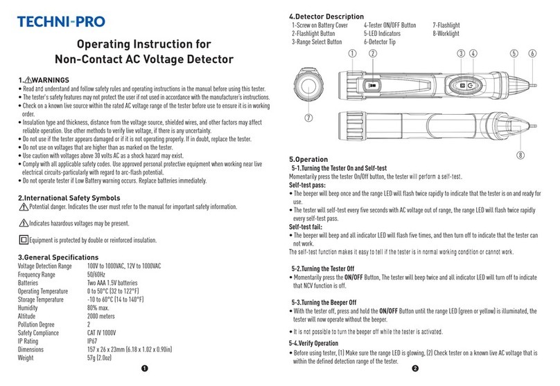
  7. Security Sensor
  8. •
  9. D+H RT BE42-ST User manual

D+H RT BE42-ST User manual

RT BE42-ST
- Anschluss darf nur durch eine autorisierte
Elektrofachkraft erfolgen!
- Betriebsspannung 24 V DC!
- Leitungen nicht mit Starkstromleitungen zusammen verlegen!
- Nur in trockenen Räumen verwenden
Sicherheitshinweise Safety notes
- Connection must be carried out by a
certified electrical technician!
- Operating voltage 24 V DC!
- Do not run cables with together power lines!
- Use only in dry rooms
RT BE42-ST 1/2
99.820.02 3.2/01/23 Deutsch / English
Bestimmungsgemäße Verwendung
- RT-Bedieneinheit zum einsetzen in Leergehäuse RT GEH02-ALU oder
in Verbindung mit der Lüftungstaster-Bedieneinheit RT LT 45 in ein
Leergehäuse RT GEH02-LT-ALU
- Für 24 V DC D+H-Rauchabzugszentralen
- Funktionen:
· AUF-ZU
· Alarm-, Kontroll- und Störungsanzeige
· Abschaltbare akustische Alarm- und Störungsmeldung
- ZU-Taste und akustische Alarmabschaltung verdeckt liegend
Lieferumfang
- Bedieneinheit mit Platinenhalter. Ohne Gehäuse und ohne RT LT45.
Scope of supply
- Operating unit with board holder. Without housing and without RT LT45.
Intended use
- RT operating unit for insertion into empty housing RT GEH02-ALU or in
connection with vent button operating unit RT LT 45 into empty housing
RT GEH02-LT-ALU
- For 24 VDC D+H smoke vent control panels
- Functions:
· OPEN-CLOSE
· alarm-, control- and fault display
· acoustical alarm and fault signal disconnectable
- CLOSE button and acoustical alarm switching off concealed
Lüftungstaster-Bedieneinheit /
vent button operating unit
RT LT45
Bedieneinheit mit Summer /
operating unit with buzzer
RT BE42-ST
Leergehäuse für RT BE mit Öffnung für Lüftungstaster /
empty housing for RT BE with notch for vent button
RT GEH02-LT-ALU
Leergehäuse für RT BE /
empty housing for RT BE
RT GEH02-ALU
oder / or
Technische Daten
Funktionen : Alarm,
Rücksetzen über verdeckt liegende Zu-Taste
Anzeigen : Kontrolle, Alarm, Störung
Die Anzeige ist zusätzlich mit einem abschalt-
baren akustischen Signal ausgestattet.
Lautstärke : 75 dB(a)
Summerfrequenz : 3500 Hz
Impulsfrequenz : 5 Hz
Spannung : 24 V DC
Standby Strom : 8 mA
Alarmstrom : 20 mA
Alarmwiderstand : 1 kΩ
Anschluss : Schraubklemmen 2,5 mm² steckbar
Temperaturbereich : -10°C ... 50°C
Technical Data
Functions : alarm,
reset via recessed Off-button
Indications : control, alarm, malfunction
Indication is additionally provided
with a disconnectable sound signal.
Loudness : 75 dB(a)
buzz frequency : 3500 Hz
impulse frequency : 5 Hz
voltage : 24 V DC
stand-by current : 8 mA
alarm current : 20 mA
alarm resistor : 1 kΩ
connection : terminal screws 2,5 mm² pluggable
temperatur range : -10°C ... 50°C
Originalanleitung
Original instructions
Notice originale
Manual original
D+H Downloads
Anschluss / Connection
18
18
18
18
Anzeigen und Bedienung / Displays and operation
OK
** Control panel only conditional fit for useZentrale ist nur bedingt einsatzfähig /
= Anzeige leuchtet / display lightens = Anzeige blinkt / display flashes (1 Hz)
Wartung der Anlage fällig / Maintenance of system due
Störung / Malfunction
Alarm / Alarm
Anlage ist betriebsbereit / System is operable
grün /
green
rot /
red
gelb /
yellow
Beschreibung /
Description
Taster "RWA-AUF,
Alarm" /
Button "open SHEV,
alarm"
Grüne Anzeige
"Betrieb OK" /
Green indicator
"operation OK"
Taster "RWA-ZU,
Rücksetzen" /
Button "close SHEV,
reset"
Schalter "Akustische Störungs-
meldung AN - AUS" /
Switch "acoustical fault signal
ON - OFF"
Gelbe Anzeige"Akustische
Störungsmeldung AUS" / /
Yellow indicator "acoustical
fault signal OFF"
Gelbe Anzeige
"Störung" /
Yellow indicator
"malfunction"
Rote Anzeige
"Alarm" /
Red indicator
"alarm"
ON
OFF
= Anzeige leuchtet nicht / display does not lightens
Entriegelung /
release button
99.820.02 3.2/01/23
OK OK
2 2
7 7
8 83 31 16 64 45 5
12345678
RZN -K / -M / -T
RT / LE
T – K A Z S
2 28 83 31 16 64 47 75 5
10kW* 10kW*
123
RZN 43xx-E
X5 (VE 520 / VE 530)
Störung / malfunction
123 4 5 6 7 89
CPS-B
RT
T – K A Z SFE R –
* Endwiderstand wird nur in der letzten
oder einzigen Bedienstelle eingesetzt. /
Terminal resistor is only used for the
last or only operating panel.
D+H Mechatronic AG • Georg-Sasse-Str. 28-32 • 22949 Ammersbek • Germany • Tel.: +4940-605 65 239 • Fax: +4940-605 65 254 • E-Mail: [email protected] • www.dh-partner.com
© 2023 D+H Mechatronic AG, Ammersbek • Technische Änderungen vorbehalten. / Rights to technical modifications reserved.
Deutsch / English
2/2 RT BE42-ST
RT BE42-ST
letzter /
last
RT BE42-ST
erster bis vorletzter /
first to penultimate
RM
123 44 55
TMA-1-D4-D12 (CPS-M1)
X2(X5)
TKA ZSFE–
X1(X6)
S......Störung / malfunction
A......Alarm
K......Kontrolle / control
Z......ZU / close
– ......Bezugspotential / reference potential
T......Linie / line
FE ...Funktionserde / functional earth
ST – K A Z
ST – K A Z
ST – K A Z
ST – K A Z

Other D+H Security Sensor manuals

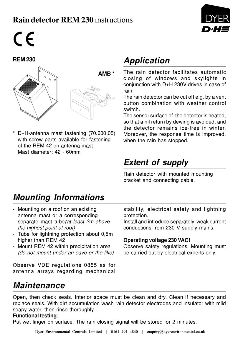
D+H REM 230 User manual

D+H

D+H REM 230 User manual

D+H REM 42 User manual

D+H

D+H REM 42 User manual

D+H PD-C180i/16 DH User manual

D+H

D+H PD-C180i/16 DH User manual

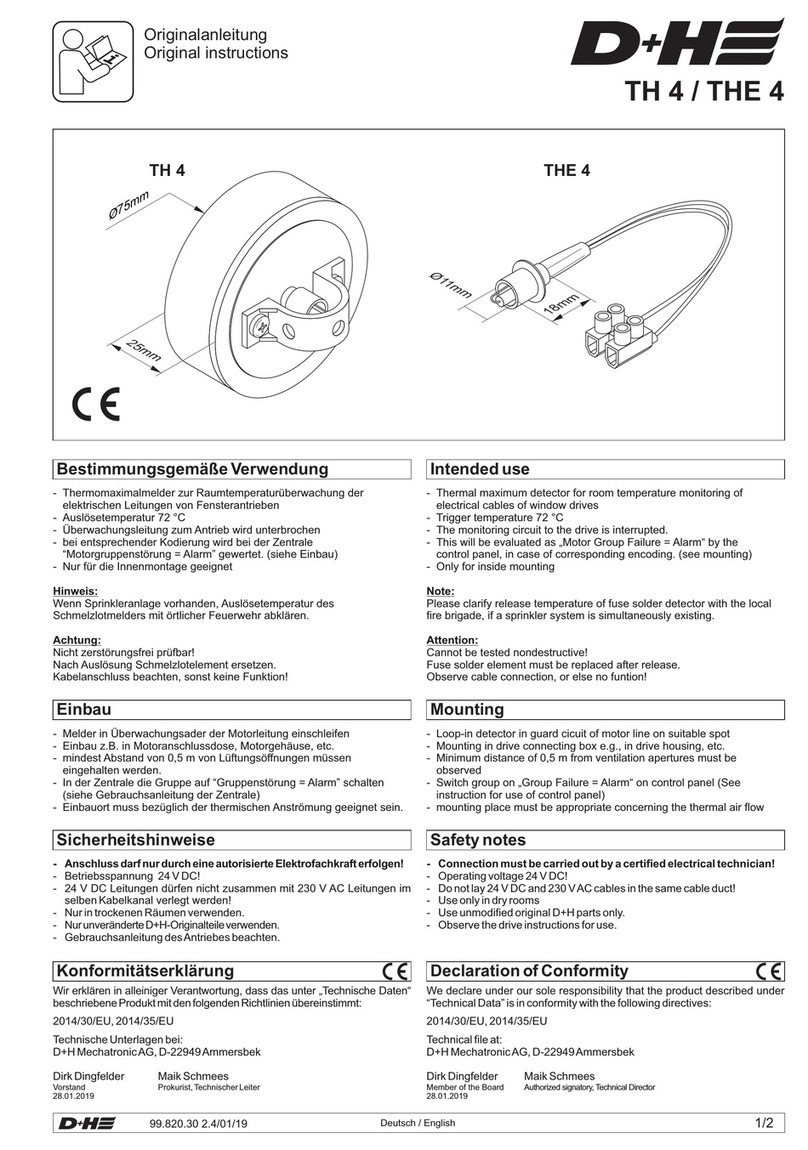
D+H TH 4 User manual

D+H

D+H TH 4 User manual

D+H VRS 10 User manual

D+H

D+H VRS 10 User manual

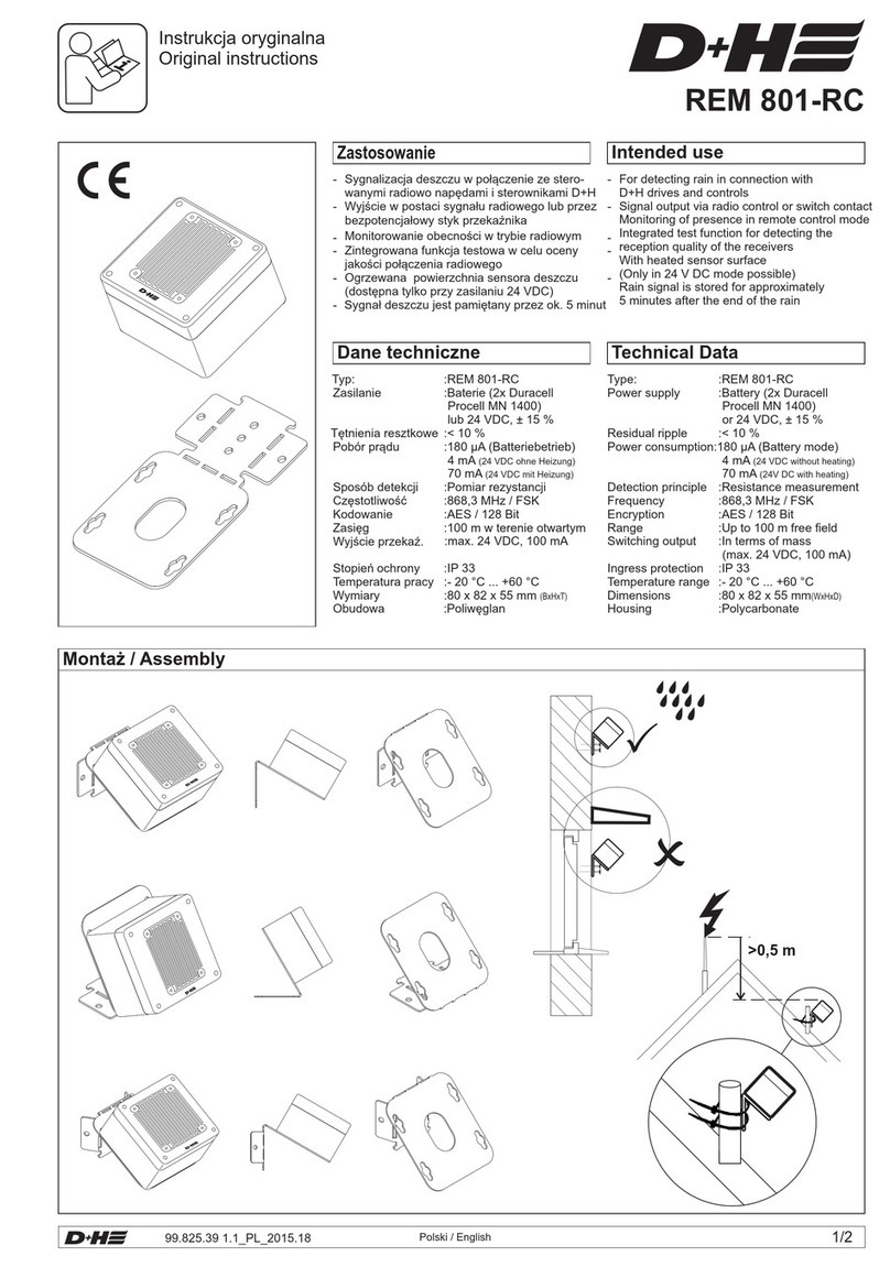
D+H REM 801-RC User manual

D+H

D+H REM 801-RC User manual

Popular Security Sensor manuals by other brands

Endress+Hauser Prosonic FDU83 Safety instructions for electrical apparatus certified for use in explosion-hazardous areas

Endress+Hauser

Endress+Hauser Prosonic FDU83 Safety instructions for electrical apparatus certified for use in explosion-hazardous areas

Busch-Jaeger Prasenz tech 6813-101 manual

Busch-Jaeger

Busch-Jaeger Prasenz tech 6813-101 manual

elobau N3 Series manual

elobau

elobau N3 Series manual

Elko inels RFSF-1B quick start guide

Elko

Elko inels RFSF-1B quick start guide

Ryobi ESF5000 Operator's manual

Ryobi

Ryobi ESF5000 Operator's manual

Roger Technology R90 Series INSTRUCTIONS AND RECOMMENDATIONS FOR THE INSTALLER

Roger Technology

Roger Technology R90 Series INSTRUCTIONS AND RECOMMENDATIONS FOR THE INSTALLER

tams elektronik RCD-1 manual

tams elektronik

tams elektronik RCD-1 manual

THORLABS PDA500 Setup

THORLABS

THORLABS PDA500 Setup

Velleman High-Q Velleman-kit K8086 Illustrated assembly manual

Velleman

Velleman High-Q Velleman-kit K8086 Illustrated assembly manual

Rielta PYRONE-SH installation guide

Rielta

Rielta PYRONE-SH installation guide

Siemens Cerberus CS1140 Planning

Siemens

Siemens Cerberus CS1140 Planning

Inficon Contura S400 Translation of the original operating instructions

Inficon

Inficon Contura S400 Translation of the original operating instructions

Radiodetection RD7100 user guide

Radiodetection

Radiodetection RD7100 user guide

Optex Fiber SenSys Laser Defender LD308SH Application note

Optex

Optex Fiber SenSys Laser Defender LD308SH Application note

GST I-9602LW Installation and operation manual

GST

GST I-9602LW Installation and operation manual

ABLE Ultima OPIR-5 Installation & maintenance instructions

ABLE

ABLE Ultima OPIR-5 Installation & maintenance instructions

AVE AF974R-DB manual

AVE

AVE AF974R-DB manual

kobi LX20 quick start guide

kobi

kobi LX20 quick start guide

manuals.online logo
manuals.online logoBrands
  • About & Mission
  • Contact us
  • Privacy Policy
  • Terms and Conditions

Copyright 2025 Manuals.Online. All Rights Reserved.