DR. BENDER BELUGA WX2 User manual

DR. BENDER GmbH
Innovative Elektrowerkzeuge
Manual for
driving machines
beluga wx2
230 V
beluga wx8
400 V
1750 1500 2400 3750 min-1
Valid from 06.2005 WX2 Art.-No. 101187 101188 Subject to alterations
WX2 FH Art.-No. 101096 101092
WX2 B Art.-No. 101382
WX8 Art.-No. 101085 101183 100387
WX8 FH Art.-No. 101118 101093
WX8 B Art.-No. 101305
BELUGA WX2 230V BELUGA WX8 400V
All rights reserved
DR. BENDER GmbH • D-75382 Althengstett • Tel 07051-9291-0 • Fax 07051-9291-91
Our website address is: http://www.dr-bender.de • e-mail: info@dr-bender.de

2
Conformity Declaration
DR.BENDER GmbH
Innovative Elektrowerkzeuge
EC Conformity Declaration
for the following DR.BENDER stone processing machines
BELUGA WX2, WX2 FH, WX2 B
BELUGA WX8, WX8 FH, WX8 B
DR.BENDER GmbH, as manufacturer, hereby declares that the electrical stone drilling machines
mentioned above comply with the requirements of the following guidelines:
-Machine guidelines (98/37/EC)
-Electromagnetic compatibility (EMC) (89/336/EEC)
-Low voltage guideline (73/23/EEC)
The following standards were applied for evaluating the machines:
a) with regard to the machine guidelines:
VDE 0740 21-22: 1994-1991
VDE 0701 Part 1: 1993
VDE 0702 Part 1: 1995
DIN EN 50144-1: 1999
DIN EN 50144-2-1: 2000
b) with regard to electromagnetic compatibility
Interfering emissions
DIN EN 55014-1: 2000 + A1: 2001 = VDE 0875 Part 14-1
DIN EN 61000-3-2: 2000
DIN EN 61000-3-3: 1995 + Cor.1: 1997 + A1: 2001
Interference immunity
DIN EN 55014-2: 1997 + A1: 2001 = VDE 0875 Part 14-2
c) with regard to the low voltage guideline
EN 61029-1: 2001
DR.BENDER GmbH
Althengstett, 26.05.2003
Industriestraße 22
D-75382 Althengstett
Tel. 07051/9291-0, Fax 07051/9291-91
B. Brehm, Management
This declaration implies no assurance of properties.
Please observe the safety regulations of the attached product documentation.

3
Contents
Page
Conformity declaration 2
Contents 3
1.0 Symbol- and Pictograph description 4
1.1 Function description 4
2.0 General instructions 5
2.1 Technical description 5
2.2 Application 5
2.3 Safety 6
3.0 Transport and storage 6
3.1 Transport 6
3.2 Storage 6
4.0 Main dimensions and technical data 7
4.1 Dimensions 7
4.1.1 Beluga WX2, 230V 7
4.2.2 Beluga WX2 FH, 230V 7
4.1.3 Beluga WX2 B, 230V 7
4.1.4 Beluga WX 8, 400V 8
4.1.5 Beluga WX8 FH, 400V 8
4.1.6 Beluga WX8 B, 400V 8
4.2 Technical Data 9
4.2.1 Beluga WX2, WX2 FH, WX2 B, 230V 9
4.2.2 Beluga WX8, WX8 FH, WX8 B, 400V 9
4.3 Noise emissions and vibrations [EN 50144] WX2, WX2 FH 9
4.4 Noise emissions and vibrations n [EN 50144] WX2 B, WX8, WX8 FH, WX8 B 9
4.5 Operating temperatures 10
5.0 Commissioning 10
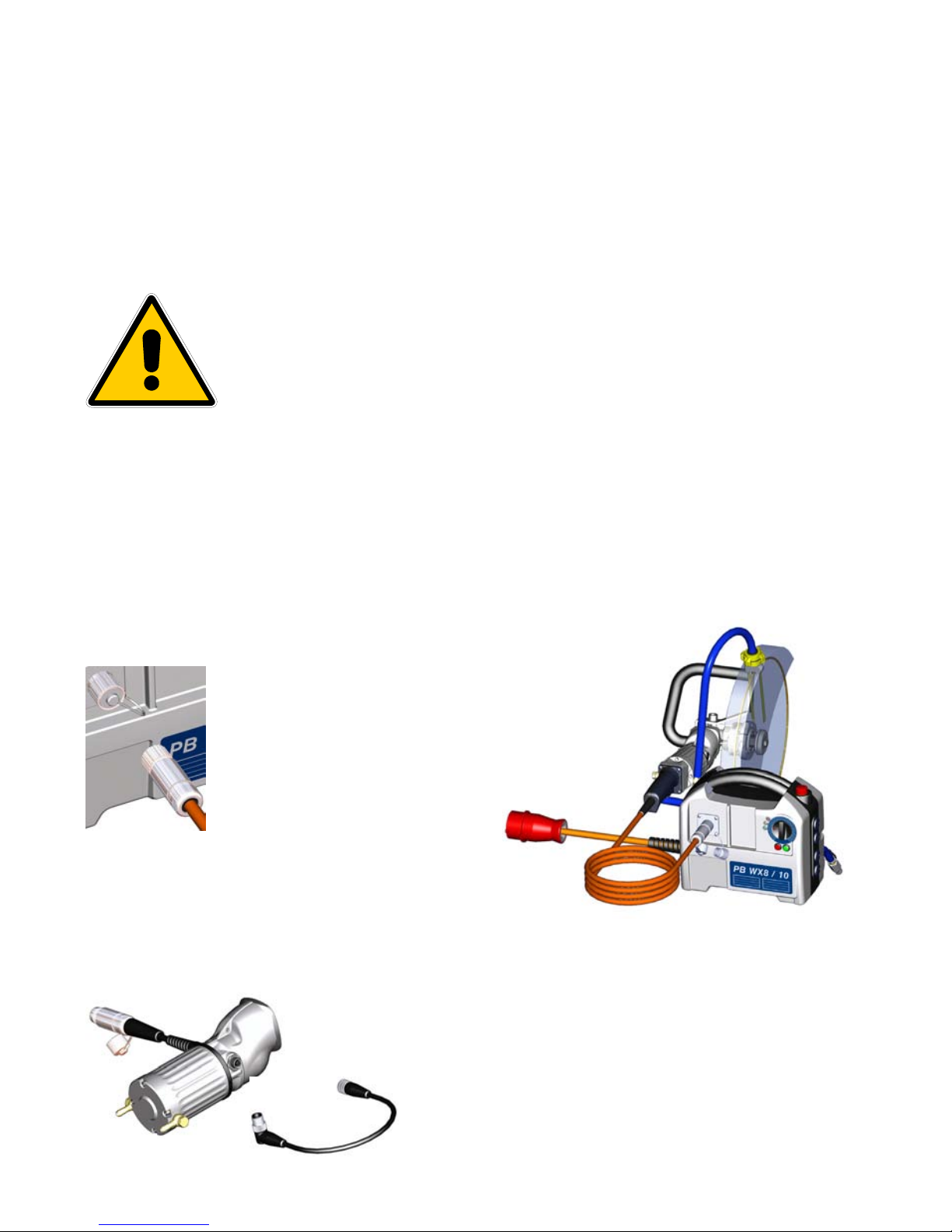
5.1 Mains connection 10
5.2 Control connecting sleeve - WX2, WX8 10
5.3 Water connection 11
5.4 Bayonet catch 11
5.5 Handle adjustment - WX8 FH 12
5.6 Saw blades and core bits 12
6.0 Safety instructions 12
7.0 Maintenance and care 13
7.1 Daily care 13
7.2 After approx. 150 hours of use 13
7.3 Quarterly 13
8.0 Speed adjustment dependent on the cutting speed 13
9.0 Warranty 13
10.0 General safety instructions 14
11.0 Spare parts lists 16
11.1 Beluga WX2, 230V 16
11.2 Beluga WX2 FH, 230V 16
11.3 Beluga WX2 B, 230V 18
11.4 Beluga WX8, 400V 18
11.5 Beluga WX8 FH, 400V 20
11.6 Beluga WX8 B, 400V 22
11.7 Motor, compl. WX2, WX2 FH, 230V 24
11.8 Motor, compl. WX8, WX8 FH, 400V 26
11.9 Motor, compl. WX2 B, 230V 28
11.10 Motor, compl. WX8 B, 400V 30
11.11 Gear compl. WX2, WX8 32
11.12 Gear compl. WX2FH, WX8B 34

4
Warning
It is compulsory to observe the safety instructions included in this manual!
Special designs and versions may differ from the standard models in terms of their technical
details. If any points are unclear, we urgently recommend that you contact DR.BENDER GmbH,
indicating the machine type and machine number.
1.0 Symbol- and Pictograph description
This sign tells you rules, if you not pay attention for this your health and the function of
the machine is in danger. You have no warranty if the machine breaks down because
you not looking about this.
1.1 Function description
Control box mains
connection: 230V
1000 Hz
Motor controller
on/off switch
Bayonet
connection
Control box mains
connection: 400V
1000 Hz
Bayonet
connection
Handle
Handle
Motor controller
on/off switch
Handle
Control line connection
for external on/off
switch and motor
controlle
r
Water
connection

5
2.0 General instructions
2.1 Technical description
BELUGA represents a completely new generation of driving machines used for stone processing. The
highly extensive modular design principle provides the nowadays so important flexibility in performing
cutting operations in concrete and stone. In the process, quite newly developed high frequency elements
are employed in the motor. The frequency range is adjusted within 0 – 1000 Hz by means of the frequency
changer integrated in the Powerbox. At 1000 Hz, the rotor reaches a speed of 30,000 min-1. A main
advantage results from a weight / performance ratio (ORCA: motor output = 11 kW / weight = 21.5 kg ->
0.51) so far unequaled with the conventional technology, such as the BBM33extra type (motor output = 2.4
kW / weight = 13.5 kg -> 0.17). This means that the weight of the machine could be reduced three times by
means of the high frequency technology. Further advantages result from the infinitely variable speed
regulation. Thus, each tool diameter may be assigned its optimum speed, in order to achieve the best
cutting speed possible at the tool. Furthermore, the speed may be continuously reduced in the process
when steel reinforcements appear, thus providing its optimum adaptation to the working progress. In this
case, it is possible to run at much higher cutting speeds (Caution! They depend on the tool), achieving an
up to 150% faster working progress. In the case of conventional machines, the torque dramatically
decreases at high speeds, rendering this advantage impossible.
2.2 Application
The BELUGA driving machines and the appropriate Powerboxes can be used for the purposes outlined by
the data on the model plate. If you are using special machines, the details in the quotation and order
confirmation also apply.
The driving machines and the Powerboxes are supplied as standard in protection class I; only this can
guarantee the full high quality protection of the FI switch.
If you use suitable saw blades and core bits, you will be able to cut in the most diverse material types:
- concrete (even if it contains thick reinforcement steel)
- sandstone and limestone
- all building materials for solid walls
- asphalt carpets
The machines must be connected as follows:
-BELUGA WX2:
to the PB WX2 type Powerbox;
-BELUGA WX8:
to the PB WX8/10 or PB WX8/10 VB type Powerboxes.

6
2.3 Safety
Warning
Before using the machine for the first time, check the conformity of the data on
the model plate with the mains voltage and frequency. Voltage deviations of
± 5 % and/or voltage deviations of ± 2 % are permissible. Repairs may be
carried out only by adequately qualified persons, based on their training and experience.
The following points are to be given special attention:
- the technical data and information on the permitted use of the machine (commissioning, ambient
and operating conditions) which are set out, among others, in the catalogue, the operating manual,
the model plate data and the other product information;
- the relevant accident prevention regulations;
- the professional use of tools;
- the use of personal safety equipment.
3.0 Transport and storage
3.1 Transport
Warning
The driving machines are to be checked for signs of transport damage on
receipt. Possibly existing damages must be basically documented in writing.
3.2 Storage
If possible, the storage site should be dry, clean and have a constant temperature. To ensure that the film
of lubricant in the bearings and sealing system is not lost, the motor shaft should be turned through several
revolutions by hand after a lengthy period of storage, for example at monthly intervals. The roller bearings
in the motors should be replaced (or re-greased) if the period between delivery and commissioning is over
four years. If the machines are stored in adverse conditions, this period will be considerably reduced.

7
4.0 Main dimensions and technical data
4.1 Dimensions
4.1.1 Beluga WX2, 230V
4.1.2 Beluga WX2 FH, 230V
4.1.3 Beluga WX2 B, 230V

8
4.1.4 Beluga WX8, 400V
4.1.5 Beluga WX8 FH, 400V
4.1.6 Beluga WX8 B, 400V

9
4.2 Technical Data
4.2.1 Beluga WX2, WX2 FH, WX2 B, 230V
Gearbox variant 1500 1750 2400 3750 min-1
Rated voltage 230 V
Current consumption 16 A
Power requirement 3,500 W
Frequency 1000 Hz
Idling speed 0 - 1500 0 – 1750 0 - 2400 0 – 3750 min-1
Full speed 0 - 1500 0 – 1750 0 - 2400 0 – 3750 min-1
Output rating 2.400 W
Torque 20 17.5 12.5 8 Nm
Protection class IP 67 -
Cooling medium air water air air -
Weight WX2 3.0 kg
Weight WX2 FH 3.1 kg
Weight WX2 B 3.6 kg
4.2.2 Beluga WX8, WX8 FH, WX8 B, 400V
Gearbox variant 1500 1750 2400 3750 min-1
Rated voltage 400 V
Current consumption 15 A
Power requirement 8,000 W
Frequency 1000 Hz
Idling speed 0 - 1500 0 - 1750 0 - 2400 0 – 3750 min-1
Full speed 0 - 1500 0 - 1750 0 - 2400 0 – 3750 min-1
Output rating 5,400 W
Torque 40 35 25 16 Nm
Protection class IP 67 -
Cooling medium water -
Weight WX8 3.3
Weight WX8 FH 3.5
Weight WX8 B 3.6 kg
4.3 Noise emissions and vibrations [EN 50144]
WX2, WX2 FH
Noise pressure level Noise power level Vibration
db(A) dB m/s2
84 98 < 2.5
4.4 Noise emissions and vibrations [EN 50144]
WX2 B, WX8, WX8 FH, WX8 B
Noise pressure level Noise power level Vibration
db(A) dB m/s2
72 84 < 2.5

10
4.5 Operating temperatures
In case of sufficient cooling of the system, the Beluga WX8, WX8 FH, WX8 B and WX2 B take on the
cooling water temperature. The plastic casing of the hand-guided Beluga WX2 and WX2 FH take on
temperatures of up to 35°C. The gear box of Beluga may take on temperatures of up to 80°C. You should
not worry about this, as it is normal. That is why you should hold the machine by the handles.
5.0 Commissioning
5.1 Mains connection
Important
Check that the mains voltage ids identical to the voltage specified on the model
plate. Also check that the frequency is identical to the frequency specified on
the model plate. Use only original mains cables:
230V connection cable - WX2, WX2 FH Art.-No. 801806
400V connection cable - WX8, WX8 FH Art.-No. 801792
The Beluga WX2 B and WX8 B type driving machines are designed for freehand cutting applications in
terms of their sense of rotation. This means that in case of a drilling application, there appears an incorrect
sense of rotation for drilling. For this purpose, a small phase changer is available, which is simply screwed
in between the plug connection of the Beluga and the Powerbox. Always pay attention to the correct sense
of rotation for each application.
230V phase changer - Art.-No. 802097
400V phase changer - Art.-No. 801812
Remove the protecting caps from
the plug connections. These
protecting caps prevent the
penetration of water in unplugged
condition, thus increasing the
service life of the high-grade cable
connections considerably.
Connect the lead of the Beluga
driving machine (e.g.. Squatina
400, see illustration on the right) to
the round socket situated on the front side of the
Powerbox. Tighten up the castle nut of the screwed
cable joint in order to obtain the required IP 67
protection.
5.2 Control connecting sleeve - WX2, WX8
The Beluga WX2 and WX8 type driving machines are not provided with
on/off switch and speed control system. That is why they have a control
connecting sleeve. It is through this sleeve that the driving machines may be
supplied with the on/off and speed control functions. This control cable will
be used, for instance, when employing the built-on gearbox
or the Squatina 350.
Use only original control lines:
Control cable – WX2, WX8 Art.-No. 802096

11
5.3 Water connection
The water should flow first through the Powerbox,
then through the driving machine and only afterwards
reach the saw blade or core bit. Therefore, connect
the water supply to the water inlet (with ball plug
valve) provided on the Powerbox. The water outlet of
the Powerbox will be connected to the water inlet of
the Beluga (for instance Squatina 400, see
illustration on the left).
Caution: if possible, do not exceed the maximum
water pressure of 3 bar.
The Powerbox and the Beluga WX2 B, WX8, WX8
FH, WX8 B type driving machines are water-cooled.
Therefore, make sure to provide sufficient cold water
in operation (the cooling water should not exceed
30°C). The machine must be operated with at least
1/2 liter water per minute at full load. Use only pure
tap water, no dirty water or sewage, otherwise the
heat transfer at the cooling surfaces is no longer ensured and the motor may be damaged irreparably.
The PB WX2 type Powerbox and the Beluga WX2, WX2 FH type driving machines are air-cooled and
consequently require no water connection.
5.4 Bayonet catch
The Beluga driving machines are provided with bayonet catch. Consequently,
several mounted tools may be operated.
Grease the shaft connecting joint.
Insert the shaft connecting joint with the adjusting spring in the bore of Beluga's
output shaft. Turn the mounted tool so that the screw heads may fit in the slots of
the bayonet.
Join the mounted tool to the Beluga.
Turn the mounted tool by 12° to the right, up to the limit.
Tighten the four M5 Allen screws by means of a plug spanner. The
water connection ring of the mounted tool may be turned by 360;
arrange the grooves as required in order to provide the optimum
access of the plug spanner to the screw heads.
Disassembly is performed in reverse order.

12
5.5 Handle adjustment - WX8 FH
5.6 Saw blades and core bits
You may use any saw blade having a connection bore of 1“ ( 25.4 mm). Use only saw blades that are
suitable for the type of stone. You will keep the driving machine in good condition if you use only saw
blades that are concentric and not deformed ones. Make sure that the diamond segments have an
adequate undercut against the saw blade.
You may use any core bits having a connection thread of 1 ¼ ” UNC or R ½ “. Use only core bits that are
suitable for the type of stone.
You will keep the driving machine in good condition if you use only core bits that are concentric and not
deformed ones.
Make sure that the diamond segments have an adequate undercut against the core bit body.
6.0 Safety instructions
Important
Only use the hand saw under supervision. Disconnect the mains plug and
check that the switch has been turned off,
-when the tools remain unsupervised,
-during setup and disassembly works,
-in case of voltage drops (PB WX8/10 below 340V),(PB WX2 below 200V),
-in case of uneven mains voltage (phase dissymmetry) or interruption of a phase (phase failure),
-for adjusting or fitting an accessory,
Switch off the machine if it stops for any reason. This will prevent its sudden starting when unsupervised.
Do not use the tool if
-a part of the casing is missing or defective,
-the switch, lead or plug connector has suffered damage (conduct a visual inspection every day!),
-when operating the equipment, no cooling water may penetrate into the motor or the electrical
components in any position of employment,
-if water drips out of the tool, stop working and have the tool inspected by an authorized service
workshop,
-after a fault, switch on the machine again only when the saw blade or the core bit can be turned
easily,
- Check the working area with a line detector to prevent cutting through electric cables, water or gas
lines, etc.

13
7.0 Maintenance and care
Warning
Pull out the mains plug before beginning any maintenance or repair work. You
must have the equipment checked by a specialized electrician after every repair
(statutory regulation pursuant to VBG4 since 1.1.1990).
7.1 Daily care
Make sure no water flows out of the tool. This will cause gear damage and may adversely affect the
electrical safety of the equipment. In this case, please seek assistance from an authorized service
workshop.
Visually inspect the switch, supply lead or plug connector for damage.
After completing the work, clean the equipment.
Make sure that no water penetrates into the tools during the cleaning process.
Empty the cooling water after using the machine. (For this, open the ball cock and completely blow off the
cooling water with compressed air). This is very important particularly in winter months because of ice
formation.
7.2 After approx. 150 hours of use
After the first 150 operation hours the transmission oil and wearing parts must be replaced if necessary.
After further in each case 250 operation hours a service is necessary.
Use only original spare parts.
7.3 Quarterly
Have the cable, switch and plug connectors inspected by a specialist (regulation pursuant to VBG4) and
document this inspection. Changing the transmission oil will produce a considerable increase in the service
life of the gear.
8.0 Speed adjustment dependent on the cutting speed
The driving machines of the Beluga type series allow for an infinitely variable speed regulation. Herewith
you may adjust the optimum cutting speed of your saw blade or core bit. This also ensures a perfect rapid
cut and it is quite easy on the tool.
9.0 Warranty
In keeping with our terms of sale, we offer a warranty for twelve months from the date of sale. This refers to
the free repair of material and workmanship defects, which were verifiably caused before the sale.
An original purchase document must always be submitted in case of a warranty claim. It has to contain the
full address of the dealer, the date of purchase and the type designation of the product. The operating
instructions of the particular product and the safety instructions must have been followed.
Damages resulting from operational faults cannot be acknowledged as warranty cases.
The products of the manufacturer have been developed and produced for specific applications. No
warranty claim is accepted in case of non-compliance with the due employment according to the operating
instructions, in case of the employment for other purposes than originally intended or the employment of
inadequate accessories.

14
The periodical maintenance and cleaning of the products according to the directions of the operating
instructions is absolutely necessary. The intervention of third persons (opening the machine) renders any
warranty claim void.
Maintenance and cleaning operations cannot be claimed on the basis of warranty.
Make sure only original spare parts and original accessories are used. They are available at the authorized
specialized product dealer. If non-original parts are used, consequential damages and increased hazard
cannot be ruled out. The producer is not liable for such damages. Disassembled or partially disassembled
hand saws and those repaired with non-original parts are excluded from the warranty.
Certain components, such as carbon brushes, ball bearings, switches, power-supply lines, gaskets, etc.,
are exposed to usage dependent or to normal wear. These wearing parts are not object of this warranty.
Wearing parts are marked on the spare parts lists.
10.0 General safety instructions
1. Read and follow these instructions before you use the tool. Keep these safety instructions in a safe
place.
2. Keep your workplace tidy. Untidiness in the workplace can cause accidents.
3. Protect yourself from electric shocks. Observe the applicable regulations. Avoid physical contact with
earthed parts, such as pipes, heaters, furnaces and refrigerators.
4. Keep children away. Do not allow other people to touch the tool or cable, keep away from your work
area.
5. Keep your tools in a safe place. Unused tools should be kept in a dry, locked room out of the reach of
children.
6. Do not overload your tool. It will work better and more safely in the specified capacity range.
7. Use the correct tool. Do not use tools that are too weak or mounted tools for heavy work. Do not use
tools for purposes and work they have not been designed for.
8. Wear suitable working clothes. Do not wear excessively baggy clothing or jewelry, which may be
caught by moving parts. For working outdoors, we recommend the use of rubber gloves and sturdy
shoes. Wear a hairnet if you have long hair.
9. Use goggles. Use a breathing mask for work that generates dust.
10. Do not use the cable for any purpose other than that for which it is designed. Do not carry the tool by
the cable and do not use it to pull the plug out of the socket. Protect the cable from heat, oil and sharp
edges.
11. Every time before you use the tool, check the connection cable and plug for signs of damage. If they
are damaged, have them replaced by a specialist. Always keep the connection cable away from the
working area of the machine.
12. Secure the work piece. Use clamps or a vice to hold the work piece. Thus it will be held more securely
than in your hand and it will allow you to use both hands to control the machine.
13. Do not overstretch yourself. Avoid abnormal body positions. Ensure that you have a stable standing
position and keep your balance at all times.
14. Look after your materials with care. Keep your tools sharp and clean so that they may work well and
safely. Follow the maintenance instructions and the tool changing indications. Check the plug and
cable at regular intervals and have them replaced by a specialist if they suffer any damage. Check the
extension cable at regular intervals and replace damaged cables. Keep the handles dry and free of oil
and grease.
15. Disconnect the mains plug from the supply when the machine is not in use, before performing
maintenance operations and when changing the tool.
16. Do not leave tool spanners on the machine. Before switching it on, check that the wrenches and
setting tools have been removed.
17. Avoid unintentional starting. Do not carry a tool that is connected to the mains supply with your finger
on the switch. Ensure that the switch is turned off when you connect the tool to the mains supply.
18. Electric tools used outdoors and in wet areas: for additional safety, mobile tools used outdoors should
be connected to the mains supply using stray current circuit breakers (FI or DI). This is particularly
important when working with freehand tools.

15
19. For outdoor work, use only extension cables, which are approved for this purpose and marked
accordingly.
20. Be vigilant at all times. Watch your work. Proceed sensibly. Do not use the tool if you are not
concentrating fully on what you are doing.
21. Important:
Safety equipment (such as overcurrent protection devices, undervoltage trips, safety couplings etc.)
are aids, yet they do not offer guaranteed safety. As a responsible manufacturer, we tailor these tools
to each other so that they offer the best possible protection. But without the care and caution of the
operator, these aids may even cause damage if they are used thoughtlessly. Have the slip couplings,
in particular, checked during the quarterly inspection to ensure that they are correctly adjusted and
function properly. This inspection should be conducted by the manufacturer or by an authorized
service outlet and documented.
22. Check the machine every day for signs of damage, conduct a visual inspection:
Before reusing the tool, carefully check the safety equipment or slightly damaged parts to ensure that
they offer perfect and proper function. Check that all moving parts function correctly, that they do not
jam and that none of the parts are damaged. All parts must be correctly fitted and satisfy all the
conditions to ensure the perfect operation of the tool. Damaged safety equipment and parts must be
repaired or replaced properly by a specialist service contractor. Do not use any tools, which cannot be
turned on and off using the switch. Pay particular attention to ensuring electrical safety: Cables?
Plugs? Switches? Do all the components satisfy safety regulations?
23. Repairs may only be carried out by trained personnel. Before being used for the first time and after all
repair work, the safety of electric tools must be checked by an electrician pursuant to VBG 4, § 5. This
inspection must also be conducted and documented at regular intervals – at least once per year.
24. Please note that as an operator, you are responsible for complying with any additional regulations. For
example, if electric tools are used in a wet and/or damp environment, the regulations of the ”Stone
and Earth” Professional Association must be satisfied.
25. Electrical safety and fire safety: just as DR. BENDER did in the last 20 years, the new version of VDE
0100 also recommends the additional safety protection and fire protection of each tool achieved by
using low cost FI and DI/PRCD circuit-breakers.

16
11.0 Spare parts lists
11.1 Beluga WX2, 230V
11.2 Beluga WX2 FH, 230V

17
Pos. Art.-No. Art.-No. Art.-No. Description Pcs.
Grb. 1500 2400 3750 min-1
1 101187 101188 - Driving machine, complete 1
2 101185 Motor, complete 1
3 101181 100292 101378 Gear, complete 1
4 900231 Washer 1
5 900181 Elastic washer 1
6 900412 Countersunk screw 1
7 301427 Pipe, complete 1
8 301425 Pipe 1
9 301426 Cover 1
10 800076 Lock washer 11
11 801699 Fillister screw 4
12 100379 Cable gland 1
13 902094 O ring 1 **
14 900337 Hexagon socket head cap screw 4
15 401428 Socket, complete 1
16 802027 Plug-in socket 1
17 801841 O ring 1 **
18 100380 Flange 1
19 902026 Hexagon socket head cap screw 3
20 801369 Cable gland 1
21 101383 Connection cable, complete 1
22 802049 Cover cap 1
Wearing parts **
Pos. Art.-No. Art.-No. Art.-No. Description Pcs.
Grb. 1500 2400 3750 min-1
1 101096 101092 - Driving machine, complete 1
2 101185 Motor, complete 1
3 101731 101732 101752 Gear, complete 1
4 801754 Earth cable 1
5 900231 Washer 1
6 900181 Elastic washer 1
7 900412 Countersunk screw 1
8 301423 Strap 1
9 800076 Lock washer 4
10 801699 Fillister screw 4
11 301424 Strap 1
12 401426 Screwed cable joint 1
13 401540 Threaded bushing 1
14 902088 O ring 1 **
15 802009 Rubber sealing 1 **
16 800162 Shim 1
17 401539 Clamping screw 1
18 100851 R casing 1
19 100986 Fan insert 1
20 801473 Plug switch 1
21 101079 Wiring harness 1
22 802068 Heat shrink hose 1
23 801361 Cap 1
24 100852 L casing 1
25 801755 Slotted cheese head screws 8
26 802049 Cover cap 1
27 802046 Cable plug 1
28 801806 Connection cable, complete 1
Wearing parts **

18
11.3 Beluga WX2 B, 230V
11.4 Beluga WX8, 400V

19
Pos. Art.-No. Description Pcs.
Grb. 1750 min-1
1 101382 Driving machine, complete 1
2 101380 Motor, complete 1
3 101350 Gear, complete 1
4 802082 Blank cover 2
Wearing parts **
Pos. Art.-No. Art.-No. Art.-No. Description Pcs.
Grb. 1500 2400 3750 min-1
1 101085 101183 - Driving machine, complete 1
2 101089 Motor, complete 1
3 101181 100292 100378 Gear, complete 1
4 900231 Washer 1
5 900181 Elastic washer 1
6 900412 Countersunk screw 1
7 100379 Cable gland 1
8 902094 O ring 1 **
9 800076 Lock washer 7
10 900337 Hexagon socket head cap screw 4
11 401428 Socket, complete 1
12 802027 Plug-in socket 1
13 801841 O ring 1 **
14 100380 Flange 1
15 902026 Hexagon socket head cap screw 3
16 801369 Cable gland 1
17 802108 Connection cable, complete 1
18 802066 Plug cap 1
Wearing parts **

20
11.5 Beluga WX8 FH, 400V
This manual suits for next models
16
Table of contents
Other DR. BENDER Power Tools manuals
Popular Power Tools manuals by other brands

Nitta
Nitta FP-120G-60 Operator's manual

Phoenix Contact
Phoenix Contact CF 3000-2,5 user manual

ITATOOLS
ITATOOLS ITA41 Operation manual & spare parts list

Everwin
Everwin FCN90L Operation and maintenance manual

Silverline
Silverline 900798 Original instructions

EIBENSTOCK
EIBENSTOCK PLD 182 Original instructions