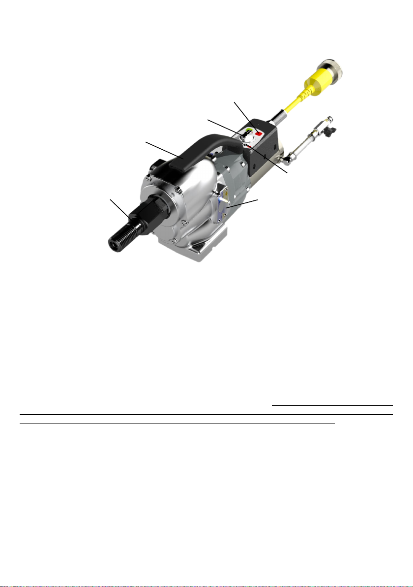
DR. BENDER RX S User manual

DR. BENDER GmbH
Innovative Power Tools
Operating Manual
Drive unit RX S / SL
HF III
Issued 05.2018 Art No.:102165 Subject to change
Art No.: 102429
Alle Rechte vorbehalten / All rights reserved
DR. BENDER GmbH • D-75382 Althengstett • Tel 07051-9291-0 • Fax 07051-9291-91
We are on the internet at http://www.dr-bender.de • email: info@dr-bender.de

2
Declaration of conformity
DR.BENDER GmbH
Innovative Power Tools
EC – Declaration of conformity for machines
Herewith, the manufacturer,
Dr. BENDER GmbH
Industriestrasse 22
75382 Althengstett
declares that the machine
RX S, RX SL
conforms with the aforementioned Directive and the following Directives
- Machinery Directive of the European Parliament and Council (EC-RL 2006/42/EC)
- Electromagnetic compatibility (EMC) (2004/108/EC)
- Low Voltage Directive (2006/95/EC)
The following harmonised standards have been used for assessment of the appliance:
EN 50144-1
EN 50144-2-1
EN 55014-1
EN 61000-3-2
EN 61000-3-3
EN 55014-2
EN 61029-1
Authorised Person for Documentation:
Min Wei
c/o Dr. Bender GmbH
Industriestrasse 22
75382 Althengstett
Deutschland
DR.BENDER GmbH Althengstett, 30.07.2018
Industriestraße 22
D-75382 Althengstett
Tel. 07051/9291-0, Fax 07051/9291-91
Min Wei, Managing Director
This Declaration does not include Assurance of Product Properties.
The Safety Instructions of the enclosed Product Documentation have to be respected.

3
Contents
Page
Declaration of conformity
2
Contents
3
1.0
Symbol and pictogram description
4
1.1
Function description
6
2.0
General instructions
6
2.1
Technical description
6
2.2
Applications
7
2.3
Safety
7
3.0
Transport and storage
7
3.1
Transport
7
3.2
Storage
7
4.0
Main dimensions and technical data
8
4.1
Dimensions
8
4.2
Technical data
8
4.3
Noise emission and vibration [EN 50144]
9
4.4
Operating temperatures
9
5.0
Commissioning
9
5.1
Mains connection
9
5.2
Water connection
9
5.3
Stone drilling machine RX S / SL
10
5.4
Drill bits
11
6.0
Safety instructions
11
7.0
Repair and maintenance
12
7.1
Daily maintenance
12
7.2
Service after approx. 120 operating hours
12
7.3
Quarterly
12
8.0
Speed setting depending on cutting speed
12
9.0
Warranty
13
10.0
General Safety Instructions
13
11.0
Spare parts lists
14
11.1
Stone drilling machine RX SL
14
11.2
Stone drilling machine RX S
15
11.3
Gear RX SL complete
16
11.4
Gear RX S complete
18
11.5
Motor complete RX S / SL
20

4
Attention
The safety instructions included in this operating manual must be followed!
Custom models and design variants may deviate from the basic type in
technical details. In the event of any discrepancies, we recommend that you contact DR.BENDER
GmbH urgently. Always give the machine type and machine number in any correspondence.
1.0 Symbol and pictograph description
Warning
Indicates instructions which may endanger your health or the functionality of the unit if
they are not followed. The warranty shall become null and void if you cause defects to
the unit by non-compliance with these instructions.
Warning
Warning of dangerous electrical voltage.
Before work is performed in this specially marked section, the installation of the device
must be separated completely from current (voltage) and must be secured against un-
intentional power ON.
Disregard can lead to severe or deadly injuries.
Recycling
Please direct waste to recycling.
Disposal
The customary and regional laws shall be observed for disposal.

5
Safety signs on the machine
Wear safety shoes
Wear gloves
Wear a safety helmet
Wear protective goggles
Wear ear protection
Wear a breathing mask
Pull the power plug before work on the device
Read the instructions

6
1.1 Function description
2.0 General instructions
2.1 Technical description
The BELUGA represents a whole new generation of drive units for stone cutting. The exceptionally com-
prehensive modular system offers the flexibility needed today when performing cutting work in concrete
and stone. To achieve this, newly developed high-frequency motor parts are used in the motor. The fre-
quency range is controlled by the frequency converter from 0 - 1000 Hz integrated into the Powerbox. At
1000 Hz, the rotor reaches a speed of 30.000 min-1. A major benefit lies in the exceptional weight / power
ratio (motor power output = 8 kW / weight = 6.5 kg -> 1.2). Using conventional technology e.g. type
BBM33extra (motor power output = 2.4 kW / weight = 13.5 kg -> 0.17) It means that the weight of the ma-
chine has been reduced sevenfold using the high frequency technology. We have succeeded in running the
Powerbox as well as the drive units on a 230V single phase network or on a 400 V three-phase network.
This means that only one piece of equipment is needed for use on both voltage sources. Further benefits
lie in the stepless speed control. This enables the best speed to be assigned to each tool diameter, in order
to attain the best possible cutting speed on the tool. During work, the speed can be steplessly reduced if
you come up against steel reinforcements and thus can be optimised according to the progress of the work.
Here, you can run the unit at much higher cutting speeds (Attention! depends on the tool) and in doing so,
the progress of the job can be speeded up by up to 150%. With conventional machines, the torque drops
very sharply at the higher speeds. Therefore, this advantage does not apply to conventional machines.
UNC 1 ¼“ - Adapter
Lever switch
Speed control
LED indicator
On /off button
Handle

7
2.2 Applications
The drive units BELUGA and the related Powerboxes can be used according to the data attached to the
information plate. When you are using custom-built machines, the details on the quotation and the order
confirmation also apply.
The drive units and the Powerboxes are essentially Class I appliances, only this guarantees the full high-
quality protection of the residual current circuit breaker.
When suitable saw blades and drill bits are used, a wide range of materials can be cut:
- Concrete (even with strong reinforcement)
- Sandstone and limestone
- All building materials for solid walls
- Asphalt road surfacing
The machines must be connected to the Powerbox RX/SX 12.
2.3 Safety
Warning
Before commissioning, check that the mains voltage and frequency match the
data given on the information plate. ± 5 % voltage and/or ± 2 % frequency
deviation are permitted. Repairs may only be performed by suitably qualified
staff based on their training and experience.
Pay particular attention to:
- the technical data and information on the permitted use (commissioning, standard operating
conditions), which are included e.g. in the catalogue, the operating manual, the information plate
details, and other product information.
- the relevant accident prevention regulations
- the correct use of tools
- the use of personal protective equipment
3.0 Transport and storage
3.1 Transport
Warning
The drive units must be inspected for transport damage after receipt.
Any damage present must be recorded in writing.
3.2 Storage
The storage location should be dry, clean, and at a constant temperature wherever possible. In order that
the lubrication film in the bearings and the seal systems does not separate, the drive shaft should be turned
several times manually after a lengthy storage period, e.g. at monthly intervals. The roller bearings of the
devices should be replaced (or re-lubricated) if the period between delivery and commissioning is more
than 4 years. This period will be significantly reduced if the storage conditions are unsuitable.

8
4.0 Main dimensions and technical data
4.1 Dimensions
4.2 Technical data
Gearbox variants
RX S
RX SL
Rated voltage
400V ~3 / 230V ~1
V
Current rating
15 / 16
A
Power consumption
10.000 / 3.200
W
Frequency
1000
Hz
Idle - full load speed Gear 1
0 - 200
0 - 100
min-1
Idle - full load speed Gear 2
0 - 400
0 - 180
min-1
Idle - full load speed Gear 3
0 - 600
0 - 250
min-1
Idle - full load speed Gear 4
0 - 1250
0 - 480
min-1
Power output
8.900 / 2.800
W
Torque 400 V 3~ Gear 1
750
1.500
Nm
Torque 400 V 3~ Gear 2
375
830
Nm
Torque 400 V 3~ Gear 3
250
600
Nm
Torque 400 V 3~ Gear 4
120
310
Nm
Torque 230 V 1~ Gear 1
375
750
Nm
Torque 230 V 1~ Gear 2
190
415
Nm
Torque 230 V 1~ Gear 3
125
300
Nm
Torque 230 V 1~ Gear 4
60
155
Nm
Degree of protection
IP 67
-
Cooling medium
Water
-
Weight RX S / SL
17,0
kg

9
4.3 Noise emission and vibration [EN 50144]
Sound pressure level
Sound power level
Vibration
db(A)
dB
m/s2
72
84
< 2.5
4.4 Operating temperatures
If the system is sufficiently cooled, the RX S / SL attains to the cooling water temperature.
5.0 Commissioning
5.1 Mains connection
Attention
Check whether the mains voltage matches the voltage given on the information
plate. Check whether the mains voltage matches the voltage given on the
information plate.
Remove the protective covers on the plug sockets. These protective covers are designed to protect the
socket against the ingress of water when the plug is not connected. This significantly increases the service
life of the high-quality cable sockets.
Connect the electrical power lead of the Beluga RX S / SL drive unit to the round socket located on the front of
the Powerbox. Lock the bayonet sleeve of the plug socket until you hear it click, in order to maintain the
required IP 67 protection.
5.2 Water connection
The water must first flow through the Powerbox, then through the drive unit, and only then to the saw blade
or the drill bit. Therefore, connect the water supply to the water line (with tap) provided on the Powerbox.
Attention: If possible, do not exceed a maximum water pressure of 3 bar.
The Beluga RX S / SL drive units are water-cooled. During operation, always supply sufficient cold cooling
water (cooling water should not exceed 30 °C). The machine must be operated during full load operation
with at least 1/2 litre of water per minute. Only use clean tap water, no contaminated or waste water, since
otherwise the heat transfer to the cooling surfaces is no longer guaranteed and the motor may suffer
irreparable damage.
The Powerbox PB RX/SX 12 is normally air-cooled and therefore does not require the water connection.
Water supply fittings (part no. 102122) are available as custom accessories. Please take the necessary
information from the Powerbox PB RX/SX 12 operating manual.

10
5.3 Stone drilling machine RX S / SL
The Beluga RX S / SL is a very compact,
completely redeveloped stone drilling
machine for professional use. The machine
can be operated from the 230 V 1~ mains or the
400 V 3~ mains. Thus it has a very broad range of uses. An
outstanding feature is the four-speed gearbox. The slower SL
variant also has a new spindle concept, in order to change to a
four-hole flange system from approx. 400 mm drill bit diameter up. It
has been shown that with a high torque development
in first gear (1,500 Nm), the drill bit bore of 1 ¼“ UNC is no longer
sufficient. The axial forces that result from the thread pitch increase in such a way that the drill bit threaded
bore is expanded by approx. 2-3 mm and the drill bit cannot be separated from the stone drill machine.
The gear shift is a classic transmission shift. The first switch lever (transmission lever) switches from
tortoise (slow speed, high torque) to hare (quick speed, low torque). With the second switch lever, you can
change to an intermediate gear.
Transmission shift Gear change
In the above example, the transmission switch is on the hare symbol (blue) and the gear change lever in
the blue field is on 0 – 250 min-1, i.e. the machine is in third gear and can be regulated from 0 – 250 min-1.
BELUGA RX SL
Transmission switch on tortoise means 1st or 2nd gear 0 - 100 or 0 - 180 min-1.
Transmission switch on hare means 3rd or 4th gear. 0 - 250 or 0 - 480 min-1.
BELUGA RX S
Transmission switch on tortoise means 1st or 2nd gear. 0 - 200 or 0 - 400 min-1.
Transmission switch on hare means 3rd or 4th gear. 0 - 600 or 0 - 1,250 min-1.

11
5.4 Drill bits
You can use any drill bit with a connection thread of 1 ¼“ UNC or with a four-hole flange. Only use drill bits
that are suitable for the stone type. Using only concentric drill bits that are not deformed prolongs the
service life of the drive unit. Ensure that the diamond segments have an adequate undercut in relation to
the drill bits.
6.0 Safety instructions
Attention
The units must be attended when in use. Disconnect the mains plug and check
that the switch is disabled,
- when the units remain unattended
- during assembly and disassembly
- during voltage drop (rated voltage 400 V 3~ under 340 V), (rated voltage 230 V 1~ under 200 V),
- if the mains voltage fluctuates (phase imbalance) or during interruption of a phase (phase failure),
- when adjusting or fitting an accessory.
Switch the machine off when you stop operation for any reason. This prevents the unit from suddenly
starting while unattended.
Do not use the unit if,
- a part of the housing is missing or defective,
- There is damage to switches, lines, or plug connections (daily inspection!)
- when operating the units, cooling water must not penetrate the electrical components in whichever
location the units are used.
- If water is dripping from the unit, stop work and take the unit to an authorised service centre.
- After a break in operation, only switch on again if the saw blade or drill bit can rotate freely.
- Check the work area with a pipe detector in order to avoid cutting into electrical cables, water pipes
or gas pipes etc.

12
7.0 Repair and maintenance
Warning
Always disconnect from the mains before starting repair or maintenance work.
After any repair, the unit must be checked by a qualified electrician (legal
requirement pursuant to VBG4 since 1.1.1990).
7.1 Daily maintenance
Check that no water is leaking out of the unit. This may impair the electrical safety of the unit and lead to
damage to the gearbox. In this case, please contact an authorised service centre.
Visual inspection for damage to the switches, the lines, or the plug sockets.
Clean the units after completion of the work.
Check that no water gets into the units during cleaning.
Drain the cooling water after using the machine. (Open the tap and blow out the water using compressed
air). This is particularly important in case of frost formation in winter.
7.2 Service after 120 operating hours
A service is due after 120 operating hours. The machine counts the operating hours itself and tells you
when 120 operating hours are reached by a blue LED on the handle. All worn parts are replaced during this
service. The next service is carried out at further intervals of 120 operating hours. The service interval may
be extended by max. 10 %, so you can complete your work with the machine at your own convenience.
If the maximun service interval of 120 + 12 operating hours is exceeded, the warranty becomes null and
void.
7.3 Quarterly
Have the cables, switches, plugs checked by a qualified specialist (provision pursuant to VBG4) and record
this. Replacing the gearbox oil significantly increases the service life of the gearbox.
8.0 Speed setting depending on cutting speed
The drive units of the Beluga series allow stepless speed adjustment. You can thus set the best cutting
speed for your saw blade or drill bit. This also provides a perfect, quick cut and the service life of the tool is
also significantly extended.

13
9.0 Warranty
Pursuant to our Terms & Conditions of Sale, we offer a warranty of 12 months from the date of purchase.
This covers the free repair of material and production defects which are shown to have been caused prior
to sale.
An original sales receipt must always be produced when asserting a warranty claim. It must include the full
address of the dealer, purchase date, and type code of the product. The user manual for the relevant prod-
uct as well as the safety instructions must have been followed.
Damage caused by operating errors is not covered by the warranty.
The manufacturer’s products are developed and built for specific applications. If the product is used for
purposes other than the intended purpose based on the user manual, or in the event of misuse, or if unap-
proved accessories are used, the warranty shall become null and void.
The products must be regularly maintained and cleaned according to the instructions in the user manual.
The warranty shall become null and void in the event of an intervention by third parties (opening the ma-
chine).
The warranty does not cover maintenance and cleaning work.
You must ensure that only original spare parts and accessories are used. The products must be purchased
from an authorised dealer. If non-original parts are used, this may result in consequential damage and in-
creased risk of accidents. The manufacturer is not liable for such damage. Disassembled, partially disas-
sembled units, and units repaired with third party parts are not covered by the warranty.
Certain parts are subject to normal wear and tear depending on use. These parts include e.g. carbon
brushes, ball bearings, switches, mains cables, seals, etc. These consumable parts are not covered by the
warranty. Consumable parts are highlighted in the spare parts lists.
10.0 General Safety instructions
The general safety instructions can be found in the supplied safety instruction booklet.

14
11.0 Spare parts lists
11.1 Stone drilling machine RX SL
Item
Part no.
Description
No.
1
102429
Stone drilling machine RX SL
1
2
102428
Gear complete RX SL
1
3
201190
Motor complete
1
4
802403
Water hose
1 **
Wearing parts **

15
11.2 Stone drilling machine RX S
Item
Part no.
Description
No.
1
102431
Stone drilling machine RX S
1
2
102430
Gear complete RX S
1
3
201190
Motor complete
1
4
802403
Water hose
1 **
Wearing parts **

16
11.3 Gear complete RX SL

17
Item
Part no.
Description
No.
Item
Part no.
No.
1
102428
Gear complete
1
56
401684
O-ring
1 **
2
102160
Lower flange
1
57
201189
Housing
1
3
101162
O-ring
1 **
58
800077
Lock washer
4
4
901210
Rotary shaft seal
1 **
59
900321
Allen head screw
4
5
102170
Drill spindle complete
1
60
900708
Rotary shaft seal
1 **
6
102171
Drill spindle
1
61
801144
Lock washer
10
7
401855
Shaft sleeve
1
62
900302
Allen head screw
4
8
401204
Shaft sleeve
1
63
800077
Lock washer
2
9
901179
Tapered roller bearing
1 **
64
900309
Allen head screw
2
10
902120
Snap ring
1
65
101178
O-ring
1 **
11
102172
Idler 4
1
66
101179
Switching handle complete
1
12
802015
Retainer ring
1
67
802577
O-ring
2 **
13
900013
Compression spring
2
68
401808
Plate complete
1
14
900014
Ball
2
69
802055
Raised head screw
8
15
102202
Control sleeve
1
70
102195
Switching handle complete
1
16
102174
Idler 3
1
71
401813
Plate complete
1
17
802016
Retainer ring
1
72
900304
Allen head screw
6
18
901178
Tapered roller bearing
1 **
73
800028
Sealing ring
1 **
19
102179
Gear shaft 2 complete
1
74
902028
Screwed seal plug
1
20
102173
Gear shaft 2
1
75
301613
Handle
1
21
102176
Idler 1
1
76
401807
Soft grip
1
22
802015
Retainer ring
2
77
900323
Allen head screw
4
23
900013
Compression spring
2
78
802402
Quick-lock screw fitting
1
24
900014
Ball
2
79
301646
UNC adapter
1
25
102202
Control sleeve
1
80
401828
Allen head screw
1
26
102177
Idler 2
1
27
901258
Snap ring
1
28
901016
Dowel pin
2
29
102175
Wheel 2
1
30
901178
Tapered roller bearing
2 **
31
102156
Gear housing
1
32
102180
Gear shaft 1 complete
1
33
102178
Pinion shaft
1
34
902093
Groove ball bearing
2 **
35
901247
Shaft key
1
36
301597
Clutch wheel
1
37
900210
Snap ring
1
38
900715
Rotary shaft seal
2 **
39
900716
Retainer ring
1
40
302268
Gear V complete
1
41
201087
Top flange
1
42
901139
Groove ball bearing
2
43
301385
Gear shaft 2V
1
44
901071
Dowel pin
2
45
302267
Gear 2 slip coupling
1 **
46
302249
Hub
1
47
401563
Brake disc
4 **
48
401562
Support washer I
2 **
49
401339
Plate spring
1
50
301252
Hub
1
51
401561
Support washer A
1 **
52
401566
Nut
1
53
101866
Pin
1
54
800107
Shim washer
1
55
900209
Snap ring
1
Wearing parts **
80 401830 Allen head screw 1
option core drill bit short

18
11.4 Gear complete RX S

19
Item
Part no.
Description
No.
Item
Part no.
No.
1
102430
Gear complete
1
57
401684
O-ring
1 **
2
102160
Lower flange
1
58
201189
Housing
1
3
101162
O-ring
1 **
59
800077
Lock washer
4
4
901210
Rotary shaft seal
1 **
60
900321
Allen head screw
4
5
102170
Drill spindle complete
1
61
900708
Rotary shaft seal
1 **
6
102171
Drill spindle
1
62
801144
Lock washer
10
7
401855
Shaft sleeve
1
63
900302
Allen head screw
4
8
401204
Shaft sleeve
1
64
800077
Lock washer
2
9
901179
Tapered roller bearing
1 **
65
900309
Allen head screw
2
10
902120
Snap ring
1
66
101178
O-ring
1 **
11
102172
Idler 4
1
67
101179
Switching handle complete
1
12
802015
Retainer ring
1
68
902094
O-ring
2 **
13
900013
Compression spring
2
69
401808
Plate complete
1
14
900014
Ball
2
70
802055
Raised head screw
8
15
102202
Control sleeve
1
71
102195
Switching handle complete
1
16
102174
Idler 3
1
72
401813
Plate complete
1
17
802016
Retainer ring
1
73
900304
Allen head screw
6
18
901178
Tapered roller bearing
1 **
74
800028
Sealing ring
1 **
19
102179
Gear shaft 2 complete
1
75
902028
Screwed seal plug
1
20
102173
Gear shaft 2
1
76
301613
Handle
1
21
102176
Idler 1
1
77
401807
Soft grip
1
22
802015
Retainer ring
2
78
900323
Allen head screw
4
23
900013
Compression spring
2
79
802402
Quick-lock screw fitting
1
24
900014
Ball
2
80
301646
UNC adapter
1
25
102202
Control sleeve
1
81
401828
Allen head screw
1
26
102177
Idler 2
1
27
901258
Snap ring
1
28
901016
Dowel pin
2
29
102175
Wheel 2
1
30
901178
Tapered roller bearing
2 **
31
102156
Gear housing
1
32
102180
Gear shaft 1 complete
1
33
102178
Pinion shaft
1
34
902093
Groove ball bearing
2 **
35
901247
Shaft key
1
36
301644
Clutch wheel
1
37
402099
Sleeve
1
38
900210
Snap ring
1
39
900715
Rotary shaft seal
2 **
40
900716
Retainer ring
1
41
302270
Gear V complete
1
42
201087
Top flange
1
43
901139
Groove ball bearing
2
44
301643
Gear shaft 2V
1
45
901071
Dowel pin
2
46
302267
Gear 2 slip coupling
1 **
47
302249
Hub
1
48
401563
Brake disc
4 **
49
401562
Support washer I
2 **
50
401339
Plate spring
1
51
401561
Support washer A
1 **
52
301252
Hub
1
53
401566
Nut
1
54
101866
Pin
1
55
800107
Shim washer
1
56
900209
Snap ring
1
Wearing parts **
80 401830 Allen head screw 1
option core drill bit short

20
11.5 Motor complete RX SL / S
This manual suits for next models
3
Table of contents
Other DR. BENDER Power Tools manuals
Popular Power Tools manuals by other brands

GMN
GMN SNAPODRILL SD33 Technical specifications

Porter-Cable
Porter-Cable 7403 instruction manual

BIRD
BIRD Termaline Series Operation manual

Master Appliance
Master Appliance 1425-3550 FPM130-900F instruction manual

Stanley
Stanley FatMax FME340 Original instructions

Master
Master EH 4 operating instructions

Craftsman
Craftsman Hammerhead 320.38600 Operator's manual

Sears
Sears CRAFTSMAN owner's manual

Jet
Jet JWJ-8CS Operating instructions and parts manual

Larzep
Larzep ECE02015-CE instruction manual

Dynaplug
Dynaplug Mini Pro Inflator quick start guide

Worx Professional
Worx Professional Sonicrafter WU678 manual