manuals.online logo
Brands
  1. Home
  2. •
  3. Brands
  4. •
  5. Dräger Medical
  6. •
  7. Oxygen Equipment
  8. •
  9. Dräger Medical EvitaXL Setup guide

Dräger Medical EvitaXL Setup guide

All rights reserved. Copyright reserved • R5664590_Front_panel_L2_Vers_1_0.fm 03.03.03 • Repair instructions • Version 1.0 • Released
Dräger Medical AG & Co. KGaA • EvitaXL 1
Repair instructions General
Front frame, complete 1 General
In case of repair, replace the “complete front frame”.
The “front frame, complete”, comprises the front frame,
the label (EvitaXL), and the front membrane.
1.1 Replacing the front frame
1 Switch off the device.
2 Unplug the power plug of the device from the socket-
outlet.
3 Disconnect the compressed-gas supply hoses from the
central gas supply.
4 Create ESD conditions.
5 Remove the control unit from the interlock of the device
and place it on a static-dissipative mat.
In case of repair, remove the keypad labeling strip
from the faulty front frame and use it in the new front
frame!
Electrostatic discharge may damage electrostatic
sensitive devices. When handling electrostatic
sensitive devices, use a static-dissipative mat
and a static dissipative wrist strap.
All rights reserved. Copyright reserved • R5664590_Front_panel_L2_Vers_1_0.fm 03.03.03 • Repair instructions • Version 1.0 • Released
Dräger Medical AG & Co. KGaA • EvitaXL 2
Repair instructions General
6 Unscrew the screws of the plug-in connector (Fig. 1/1)
on the back of the control unit, and disconnect the
connecting cable from the control unit.
Fig. 1 Plug-in connector
7 Place the control unit on the static-dissipative mat.
8 Remove the screws (Fig. 2/1).
Fig. 2 Rear panel of the control unit
9 Remove the rear panel and put it aside.
10 Pull out the cable connector (Fig. 3/1).
All rights reserved. Copyright reserved • R5664590_Front_panel_L2_Vers_1_0.fm 03.03.03 • Repair instructions • Version 1.0 • Released
Dräger Medical AG & Co. KGaA • EvitaXL 3
Repair instructions General
Fig. 3 Cable connector
11 Hold the flex cable near the connection socket and pull
it out slowly and carefully (Fig. 4).
Fig. 4 Adapter PCB, flex cable
12 Remove the screws (Fig. 5/1).
13 Carefully remove the installation frame with display
from the front frame and place it aside (Note: the
touchscreen is only loosely mounted in the front
frame with a sealing; if the sealing sticks to the
display, the touchscreen could be unintentionally
removed in the process and might fall down!).
All rights reserved. Copyright reserved • R5664590_Front_panel_L2_Vers_1_0.fm 03.03.03 • Repair instructions • Version 1.0 • Released
Dräger Medical AG & Co. KGaA • EvitaXL 4
Repair instructions General
Fig. 5 Front frame; removing the installation frame
14 Remove the “touchscreen” together with the sealing
(Fig. 6) from the faulty front frame.
Fig. 6 Front frame; “touchscreen” with sealing
15 Remove the front membrane connector from the
Adapter PCB.
16 Remove the loudspeaker connector from the Adapter
PCB.
17 Remove the rotary transducer connector from the
Adapter PCB.
18 Remove the Adapter PCB screws.
19 Remove the Adapter PCB from the faulty front frame
and place it aside.
All rights reserved. Copyright reserved • R5664590_Front_panel_L2_Vers_1_0.fm 03.03.03 • Repair instructions • Version 1.0 • Released
Dräger Medical AG & Co. KGaA • EvitaXL 5
Repair instructions General
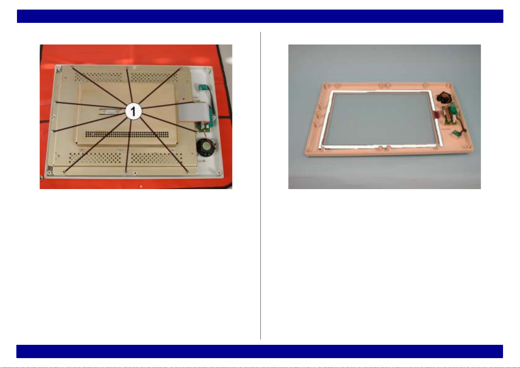
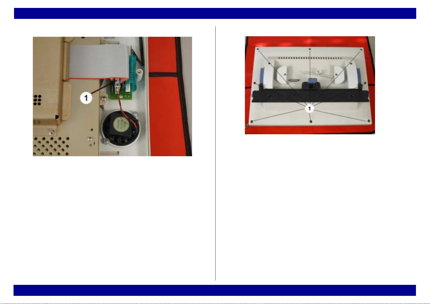
20 Remove the loudspeaker screws.
21 Remove the loudspeaker rom the faulty front frame and
place it aside.
22 Turn the front frame around.
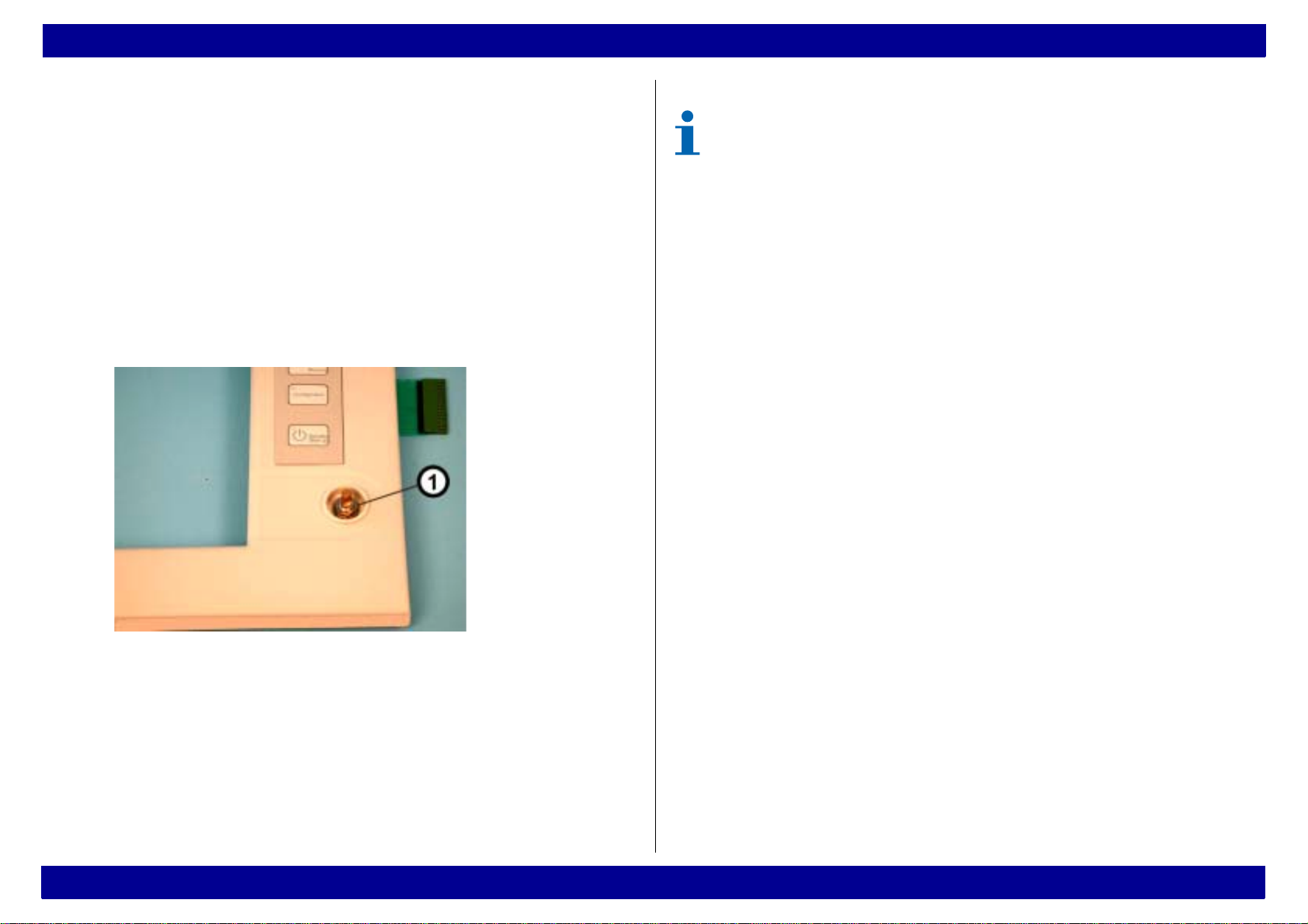
23 Carefully remove the control knob from the rotary
transducer (Note: the control knob contains a loose leaf
spring).
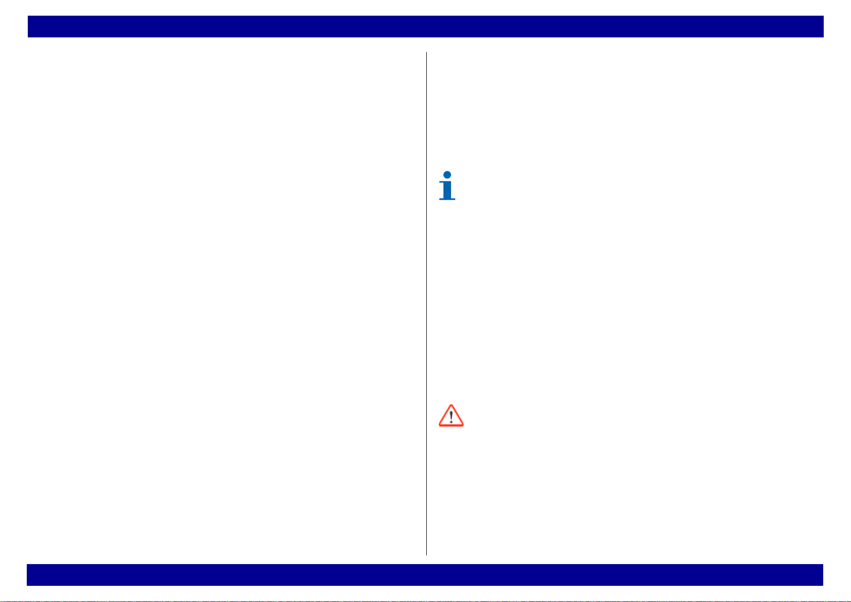
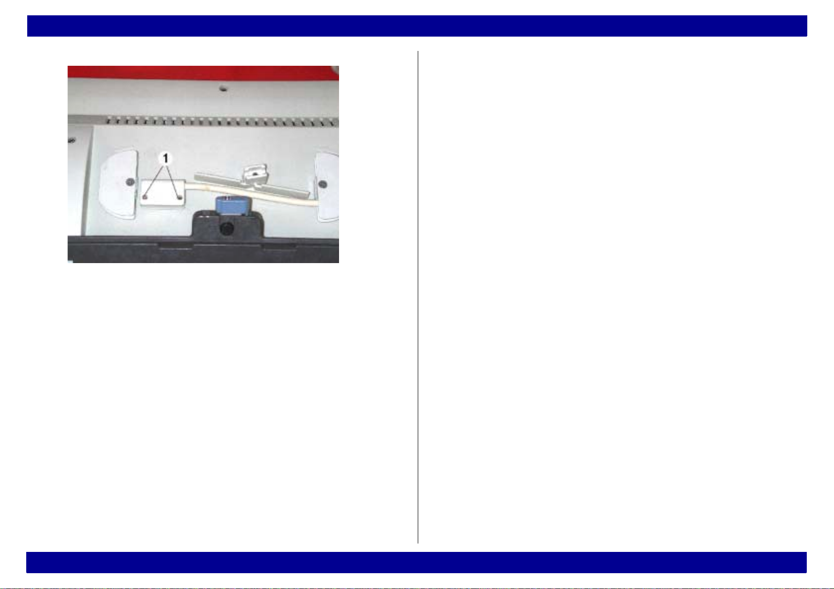
24 Remove the nut and the washer (Fig. 7/1).
Fig. 7 Rotary transducer
25 Remove the rotary transducer from the faulty front
frame and place it aside.
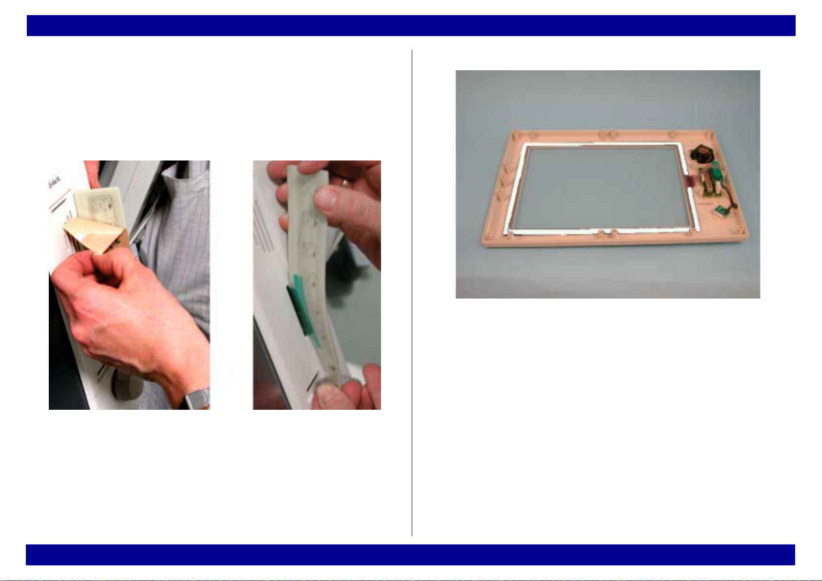
26 Remove the keypad labeling strip from the faulty front
frame and place it aside.
27 Dispose of the faulty front frame including front
membrane according to applicable waste disposal
regulations.
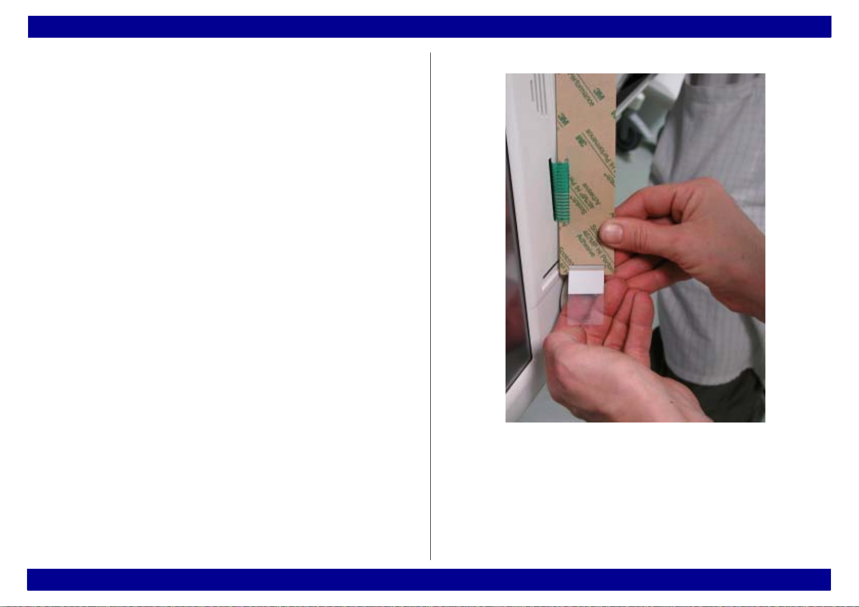
28 Attach the new “EvitaXL” label to the provided indented
space in the top right corner of the front frame.
29 Turn the new front frame around.
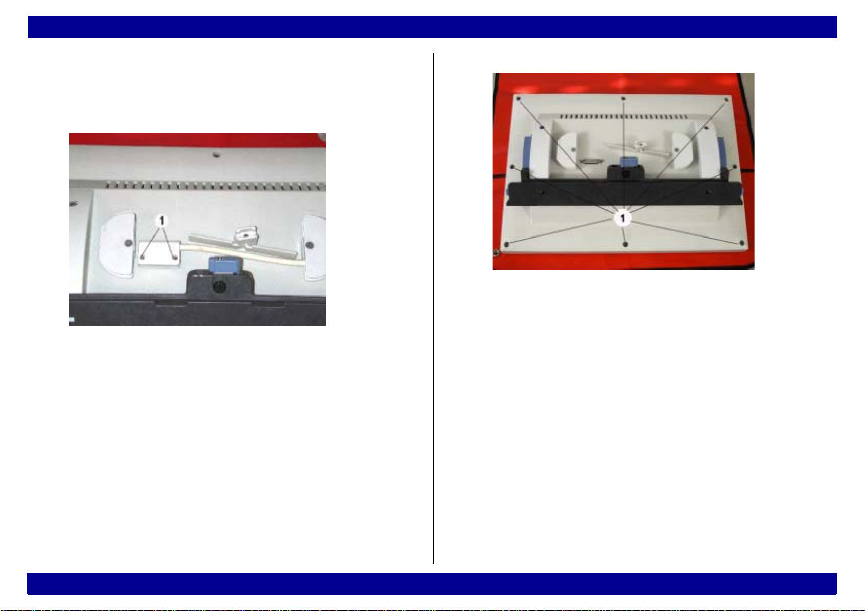
30 Secure the Adapter PCB to the new front frame using
the screws and washers.
31 Secure the loudspeaker to the new front frame using
the screws and washers.
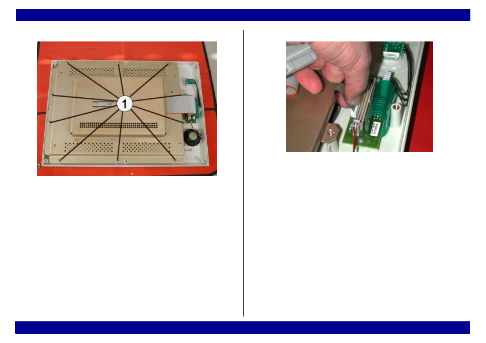
32 Plug the loudspeaker connector onto the plug-in
contact of the Adapter PCB.
33 Secure the rotary transducer to the front frame using
the washer and nut.
34 Plug the rotary transducer connector onto the plug-in
contact of the Adapter PCB.
35 Push the control knob including leaf spring onto the
rotary transducer (Note: Observe clamping position of
the leaf spring, correct if necessary).
A faulty front frame including front membrane is
special waste. Dispose of a faulty front frame
including front membrane according to applicable
waste disposal regulations.
All rights reserved. Copyright reserved • R5664590_Front_panel_L2_Vers_1_0.fm 03.03.03 • Repair instructions • Version 1.0 • Released
Dräger Medical AG & Co. KGaA • EvitaXL 6
Repair instructions General
36 Thread the flex cable of the front membrane (Fig. 8)
through the slot in the front frame, and plug the flex
cable connector onto the plug-in contact on the
Adapter PCB.
37 Push the keypad labeling strip from the old frontframe
(Fig. 8) into the front membrane as far as it will go
(Note: the labeled side must be visible!).
Fig. 8 Keypad labeling strip
All rights reserved. Copyright reserved • R5664590_Front_panel_L2_Vers_1_0.fm 03.03.03 • Repair instructions • Version 1.0 • Released
Dräger Medical AG & Co. KGaA • EvitaXL 7
Repair instructions General
38 Remove the complete protective foil from the front
membrane, insert the protruding end of the keypad
labeling strip through the slot in the front frame, and
attach the front membrane to the front frame making
sure it is aligned properly, see Fig. 9.
Fig. 9 Attaching the front membrane
39 Place the “Touchscreen” (Fig. 10) into the front frame
(Note: the rough side of the “Touchscreen” must
face outward!).
Fig. 10 Front frame; “touchscreen” with sealing
40 Clean the inner side of the “Touchscreen” with a mild
window cleaning agent and a cloth.
41 Secure the installation frame to the front frame using
the screws (Fig. 11/1).
All rights reserved. Copyright reserved • R5664590_Front_panel_L2_Vers_1_0.fm 03.03.03 • Repair instructions • Version 1.0 • Released
Dräger Medical AG & Co. KGaA • EvitaXL 8
Repair instructions General
Fig. 11 Front frame; installing the installation frame
42 Turn the front frame around and check whether the
touchscreen lies flat in the front frame, correct the
position of the installation frame (Note: there should
be no gap between touchscreen and front frame!).
43 Hold the flex cable near the connection socket and
push it slowly and carefully into the connection socket
of the Adapter PCB (Fig. 12).
Fig. 12 Adapter PCB, flex cable
44 Plug the cable connector (Fig. 13/1) into the connection
socket of the Adapter PCB.
All rights reserved. Copyright reserved • R5664590_Front_panel_L2_Vers_1_0.fm 03.03.03 • Repair instructions • Version 1.0 • Released
Dräger Medical AG & Co. KGaA • EvitaXL 9
Repair instructions General
Fig. 13 Cable connector
45 Place the rear panel onto the front frame and secure it
with the screws (Fig. 14/1).
Fig. 14 Rear panel of the control unit
46 Plug the connection cable into the control unit, and
secure the plug-in connector to the rear panel of the
control unit using the screws (Fig. 15/1).
All rights reserved. Copyright reserved • R5664590_Front_panel_L2_Vers_1_0.fm 03.03.03 • Repair instructions • Version 1.0 • Released
Dräger Medical AG & Co. KGaA • EvitaXL 10
Repair instructions General
Fig. 15 Plug-in connector
47 Push the control unit into the interlock of the device.
48 Plug the power plug of the device into the socket-
outlet.
49 Switch the device on.
50 Perform “electrical safety tests” and “function tests” as
described in the PMS procedure. For the USA and
Canada: test according to CAN/CSA-22.2 No. 601.1-
M90.

Other Dräger Medical Oxygen Equipment manuals

Dräger Medical Permox SilentCare User manual

Dräger Medical

Dräger Medical Permox SilentCare User manual

Dräger Medical Vapor 2000 User manual

Dräger Medical

Dräger Medical Vapor 2000 User manual

Popular Oxygen Equipment manuals by other brands

wtw Oxi 330/SET Instruction manuals

wtw

wtw Oxi 330/SET Instruction manuals

Philips EverFlo Q operating instructions

Philips

Philips EverFlo Q operating instructions

Ozotech AIM BTU 1000 Installation and service manual

Ozotech

Ozotech AIM BTU 1000 Installation and service manual

Rosemount 3081FG instruction manual

Rosemount

Rosemount 3081FG instruction manual

Philips SimplyGo user manual

Philips

Philips SimplyGo user manual

SeQual Eclipse 3 user manual

SeQual

SeQual Eclipse 3 user manual

Mobiak Golden Series user manual

Mobiak

Mobiak Golden Series user manual

Respironics EverGo user manual

Respironics

Respironics EverGo user manual

Tecnocontrol TS236 User instructions

Tecnocontrol

Tecnocontrol TS236 User instructions

First Care OT-DOM-T02-TCT-4 user manual

First Care

First Care OT-DOM-T02-TCT-4 user manual

Inogen One G4 Technical manual

Inogen

Inogen One G4 Technical manual

Maxtec MAXO2+A Industrial Guide & Operating Instructions

Maxtec

Maxtec MAXO2+A Industrial Guide & Operating Instructions

AirSep Focus Portable Service manual

AirSep

AirSep Focus Portable Service manual

Emerson OxyBalance instruction manual

Emerson

Emerson OxyBalance instruction manual

manuals.online logo
manuals.online logoBrands
  • About & Mission
  • Contact us
  • Privacy Policy
  • Terms and Conditions

Copyright 2025 Manuals.Online. All Rights Reserved.