Dr. Mach LED 2MC User manual

Mach LED 2MC/SC Dr. Mach
Lamps and Engineering
59160001-MCSC Edition 06 08.05.2013 / Bak page 1/34
Instructions for use
MACH LED 2MC/SC
Mach LED 2MC ceiling light for room heights up to 2,8m
Mach LED 2SC ceiling light for room heights up to 2,8m
Mach LED 2MC ceiling light for room heights between 2,8m – 3m
Mach LED 2SC ceiling light for room heights between 2,8m – 3m
Dr. Mach GmbH u. Co., Floßmannstrasse 28, D-85560 Ebersberg
Tel.: +49 (0)8092 2093 0, Fax +49 (0)8092 2093 50

Mach LED 2MC/SC Dr. Mach
Lamps and Engineering
59160001-MCSC Edition 06 08.05.2013 / Bak page 2/34
List of contents
1.Safety instructions.....................................................................................................5
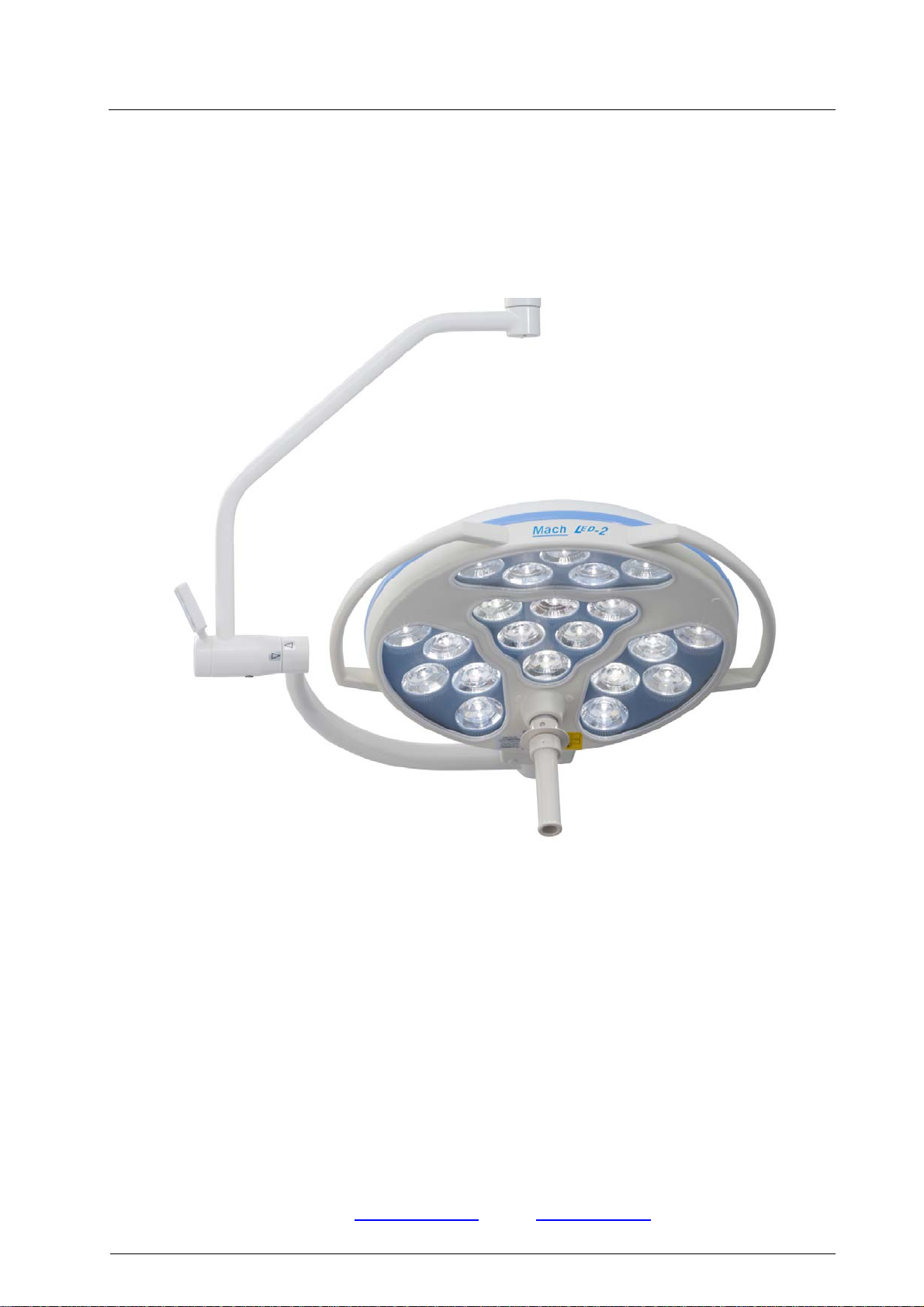
2.Brief description of the light MACH LED 2MC/SC.....................................................7
2.1.Merging of light fields................................................................................................................8
2.2.Light intensity control................................................................................................................8
3.Light functions operated at the sterilisable handle....................................................9
4.Operating the light MACH LED 2MC/SC.................................................................10
4.1.Turning the light ON and OFF...............................................................................................10
4.2.Adjusting the light field with the sterilisable handle............................................................10
4.3.Adjusting the light intensity.....................................................................................................11
4.4.Adjusting the colour temperature (Mach LED 2MC only)..................................................12
4.5.Depth light.................................................................................................................................13
4.6.Integrated OT-laser-pointer (Mach LED 2MC only)............................................................13
4.7.Deactivating all functions on the ring of the handle............................................................14
4.8.Synchronization and / or communication with the wall panel...........................................14
4.9.Basic operating mode of the communication on Dr. Mach LED lights............................15
4.10.Positioning............................................................................................................................19
5.Cleaning..................................................................................................................19
5.1.Sterilisable handle...................................................................................................................19
5.2.Lamp housing, protective disk and support system...........................................................21
6.Maintenance ...........................................................................................................22
6.1.Periodical maintenance work.................................................................................................22
7.Troubleshooting......................................................................................................23
8.Data ........................................................................................................................25
8.1.Technical data..........................................................................................................................25
8.2.Electrical data...........................................................................................................................26
8.3.Information regarding the electrical installation...................................................................26
8.4.Weights.....................................................................................................................................26
8.5.Environmental conditions.......................................................................................................27
8.6.Important remarks....................................................................................................................28
9.CE-mark..................................................................................................................28

Mach LED 2MC/SC Dr. Mach
Lamps and Engineering
59160001-MCSC Edition 06 08.05.2013 / Bak page 3/34
10. Disposal...............................................................................................................28
11. Spare parts..........................................................................................................29
11.1.Mach LED 2MC....................................................................................................................29
11.2. MachLED 2SC....................................................................................................................30
11.3.Transformer housing...........................................................................................................30
12. Spare parts list.....................................................................................................31
13. Electromagnetic compatibility ..............................................................................32

Mach LED 2MC/SC Dr. Mach
Lamps and Engineering
59160001-MCSC Edition 06 08.05.2013 / Bak page 4/34
Dear customer!
Congratulations for acquiring our new OT-light MACH LED 2MC/SC.
The new OT-light generation with LED technology supports your professiona-
lity by innovative technology and design.
The advantages of the LED technology: adjustable light colour, a life-span of
minimum 40.000 hours and an almost nonexistent heat development in the
surgeon’s head area and in the wound field.
The advantages already provided by Dr. Mach’s light technology with halogen
and gas discharge lamps have been maintained: natural colour reproduction,
exact illumination of the wound field and easy positioning of the light head.

Mach LED 2MC/SC Dr. Mach
Lamps and Engineering
59160001-MCSC Edition 06 08.05.2013 / Bak page 5/34
1. Safety instructions
Pay attention to the instructions for use when handling the lamp.
WARNING:
This device has not been designed for use in potentially explosive areas.
According to the Medical Device Regulation the light is classified under class I.
Store the OT-light in its package for at least 24 hours in the respective room before
mounting, in order to equal temperature differences.
Please read the instructions for use carefully to make the most of your lighting
system and to avoid any damages to the device.
The lights may only be repaired and special assembly work may only be carried
out on the reflector or sockets by ourselves or a company that has been expressly
authorized by us.
The manufacturer can only be made responsible for the safety of the light if repairs
and alterations are carried out by the manufacturer himself or a company that
guarantees to observe the safety regulations.
The manufacturer cannot be made liable for personal or material damages if the
light is operated inexpediently or incorrectly or used for purposes other than those
for which it is intended.
The light is to be dismantled from the spring arm in reverse order to its assembly.
This may only be carried out after the spring arm has been adjusted in height at
horizontal position since the arm is under spring tension and can bounce up.
Make sure that the light is in perfect working order before every use.
Attention, external power supply!
The light works only with an external power supply 250VA.
The external power supply used with the OT-light must be tested and validated
according to IEC 60601-1.
Attention!
A main control switch must be installed for turning the system power-off.
ATTENTION!
During the mounting of the OT-lights the entire system
(incl. the ceiling attachment) must be disconnected from mains!
A later dismounting of the lights from the spring arms or dismount-
ing the sliding contacts inside the arms is to be done ONLY AFTER
DISCONNECTING THE ENTIRE SYSTEM FROM MAINS.
Otherwise the main control board will be damaged!

Mach LED 2MC/SC Dr. Mach
Lamps and Engineering
59160001-MCSC Edition 06 08.05.2013 / Bak page 6/34
Symbols and notes used in this user manual:
This symbol means possible hazard sources. Please observe also the safety remarks and
the hazard specifications mentioned in the mounting instructions and user manuals from
Ondal company.
This symbol means possible hazard caused by electric current. Please observe also the
safety remarks and the hazard specifications mentioned in the mounting instructions and
user manuals from Ondal company.
This symbol refers to important mounting indications, useful information and operation hints.
This symbol indicates to observe the user manual.
Alternating current
Bulb
Fuse
Indication on China RoHS / Pollution control Logo China
Temperature range for transport and storage
Indication for disposal

Mach LED 2MC/SC Dr. Mach
Lamps and Engineering
59160001-MCSC Edition 06 08.05.2013 / Bak page 7/34
LASER CLASS 2
Keep the laser beam away from the patient’s and
employee’s eyes.
Danger of injury!
2. Brief description of the light MACH LED 2MC/SC
Mach LED 2MC/SC intended use:
The Mach LED 2MC/SC lighting system is designed for illuminating an examination area and surgical
field at the hospital and doctor’s practice.
Mach LED 2MC/SC indications for use:
The surgical light Mach LED 2MC is intended to illuminate the surgical field and the patient.
The surgical light Mach LED 2SC is intended to illuminate the operating site on the patient’s body with a
high intensity, shadow-free and “cold” light.
General product description
The Mach LED 2MC/SC lighting system is designed for illuminating an examination area and surgical
field at the hospital and doctor’s practice.
This light system can be added to the ceiling mounted suspension system supporting the horizontal arms
and spring arms.
The light system is operated by a keypad on the lamp head or, by special request of the customer, by a
keypad on the wall.
The surgical light Mach LED 2MC/SC is available in following versions:
- Mach LED 2MC with merging of light fields, light intensity control and colour temperature adjustment.
An integrated laser pointer is available as a standard.
- Mach LED 2SC with merging of light fields and light intensity control.
Colour temperature adjustment not available. An integrated laser pointer is available as an option.
The accessories for the Mach LED 2MC/SC lighting systems are as follows:
Camera module
Remote control for camera module
Remote control with network interface for camera module
Single monitor yoke for flat panel monitors
Double monitor yoke for flat panel monitors
Instrument trays
Trays for CRT monitors
24V DC battery backup support
Low profile wall control unit (option)
Integrated laser pointer
Sterile handle sleeves

Mach LED 2MC/SC Dr. Mach
Lamps and Engineering
59160001-MCSC Edition 06 08.05.2013 / Bak page 8/34
2.1. Merging of light fields
The OT-lights Mach LED 2MC/SC offer light
field adjustment by merging the individual
light fields of each LED unit by swiveling
them.
NOTE: This feature is activated by turning the
sterilisable handle.
2.2. Light intensity control
The OT-lights Mach LED 2MC/SC offer the feature of light intensity control.
You can adjust the light intensity between 5% and 100%; according to your requirements

Mach LED 2MC/SC Dr. Mach
Lamps and Engineering
59160001-MCSC Edition 06 08.05.2013 / Bak page 9/34
3. Light functions operated at the sterilisable handle
Depth light
The depth light can be activated by a tight-turn
of the ring at the sterilisable handle. A left-turn
of the ring switches the depth light OFF.
The depth light function on the ring is pre-
set by Dr. Mach at delivery. The customer can
transfer all other available functions of the
LED-light to the ring on request. The transfer
procedure is described in the following chap-
ters.
Merging of light fields
The four light fields of the outer LED-units are
merged to one light field by turning the handle
sleeve.
1 1
2 2

Mach LED 2MC/SC Dr. Mach
Lamps and Engineering
59160001-MCSC Edition 06 08.05.2013 / Bak page 10/34
4. Operating the light MACH LED 2MC/SC
4.1.Turning the light ON and OFF
The push button 1on the control panel turns the light
Mach LED 2MC/SC ON and OFF.
4.2.Adjusting the light field with the
sterilisable handle
The light field can be adjusted by turning the sterilis-
able handle 2.
The current size of the light field is shown by the digi-
tal display 3.
2
3

Mach LED 2MC/SC Dr. Mach
Lamps and Engineering
59160001-MCSC Edition 06 08.05.2013 / Bak page 11/34
4.3.Adjusting the light intensity
Select the desired light intensity before surgery. It is
recommended to start with 80% of the maximum
light intensity and to increase the light intensity in
time.
At these models the adjustment is done by the con-
trol panel at the cardanic bow. The intensity can be
adjusted between 5% and 100%.
By pressing push button 4the light intensity de-
creases.
By pressing the push button 5the light intensity in-
creases.
The current light intensity level is shown by the digi-
tal display 7.
ENDO-Light
By pressing the push button 6the outer LED-units
turn off while the central unit continues to burn.
The ENDO-light function can be deactivated by
pressing the button 6again.
When the ENDO-light function is activated, the
colour temperature information is faded out on
the display of the light.
Transferring the light intensity adjust-
ment function to the ring of the handle
In order to transfer the light intensity adjustment
function to the ring of the sterilisable handle, press
first push button 4or 5and then the ON/OFF button
on the key pad.
The frame around the light intensity level display
is blinking.
The previous function on the ring is de-
activated.
A right-turn of the ring at the handle increases the
light intensity by one step; a left-turn of the ring de-
creases it with one step.
5
4
7
6
Step 2
Step 1

Mach LED 2MC/SC Dr. Mach
Lamps and Engineering
59160001-MCSC Edition 06 08.05.2013 / Bak page 12/34
4.4.Adjusting the colour temperature
(Mach LED 2MC only)
Five different colour temperature values can be set at
the control panel on the lamp housing: 3750, 4000,
4250, 4500 and 4750 Kelvin.
The surgeon has the possibility to choose the opti-
mum OR light according to the tissue type and the
wound field texture.
By pressing push button 8the colour temperature
decreases.
By pressing the push button 9the colour temperature
increases.
The set colour temperature is shown by the digital
display 10.
Transferring the colour temperature
adjustment function to the ring of the handle
In order to transfer the colour temperature adjustment
function to the ring of the sterilisable handle, press
first push button 8or 9and then the ON/OFF button
on the key pad.
The colour temperature display is blinking.
The previous function on the ring is de-
activated.
A right-turn of the ring at the handle increases the
colour temperature by one step; a left-turn of the ring
decreases it with one step.
This function is not available for the
Mach LED 2SC lights.
8
10
9
Step 2
Step 1

Mach LED 2MC/SC Dr. Mach
Lamps and Engineering
59160001-MCSC Edition 06 08.05.2013 / Bak page 13/34
4.5.Depth light
You have the possibility to increase the light intensi-
ty of the central segment of the OT-light. This ena-
bles an optimum illumination of the wound field ac-
cording to its texture and the shadowing effects.
This is very important in case of small and deep
wound channels.
To activate the depth light press push button 11 on
the control panel.
4.6.Integrated OT-laser-pointer (Mach
LED 2MC only)
The built-in laser pointer always indicates the middle
of the light field and helps the surgeon to find the
optimal position of the OT-light to the wound field.
The push button 12 on the control panel turns the
laser pointer ON and OFF.
The integrated laser pointer can be activated by a
left-turn of the ring at the sterilisable handle.
The laser pointer turns off after approx. 30 seconds.
When the laser–pointer is turned on the
light intensity decreases automatically by three
steps. This is shown also by the digital display.
The light intensity can still be adjusted.
After the laser-pointer is turned off the light in-
tensity increases to the initial setting.
LASER CLASS 2
Keep the laser beam away from
the patient’s and employee’s
eyes.
Danger of injury!
The Mach LED 2SC has no integrated
laser-pointer. It is available against sur-
charge.
11
OT-lase
r
-
p
ointe
r
12

Mach LED 2MC/SC Dr. Mach
Lamps and Engineering
59160001-MCSC Edition 06 08.05.2013 / Bak page 14/34
Transferring the colour laser pointer
function to the ring of the handle
In order to transfer the laser pointer function to the
ring of the sterilisable handle, press first push button
12 and then the ON/OFF button on the key pad.
The “LASER” display is blinking.
The previous function on the ring is de-
activated.
A right-turn of the ring at the handle activates the
laser pointer; a left-turn of the ring turns it off.
4.7.Deactivating all functions on the
ring of the handle
The functions on the ring of the handle can be com-
pletely deactivated. Press first of all push button 6
(ENDO) and then the ON/OFF button on the key
pad.
The ring on the handle is without function.
In order to transfer a function on the ring, please
proceed as described in the chapters before.
4.8.Synchronization and / or commu-
nication with the wall panel
The lights Mach LED 2MC/SC can be equipped
against surcharge with the function of synchroni-
zation (combinations only) and / or communica-
tion with a wall panel.
The synchronization of two, three or four OT-
lights enables the transmission of the light inten-
sity or color temperature values set at one light to
the other OT-lights.
Additionally, the communication allows operating
the single lights from a wall panel. The settings
from the wall panel can be transmitted to the
other lights by pressing the „SYNC“ button.
The transmission of the settings to the other
lights is done by pressing the „SYNC“ button on
the key pad.
Step 2
Step 1Step 1
Step 2
Step 1

Mach LED 2MC/SC Dr. Mach
Lamps and Engineering
59160001-MCSC Edition 06 08.05.2013 / Bak page 15/34
4.9.Basic operating mode of the communication on Dr. Mach LED lights
The communication of the Dr. Mach LED lights is realized with a single-wire bus.
The members of the communication bus have star-shaped connections. All the members of the commu-
nication bus need an explicit communication number which is to be set with the first two dip-switches on
the control board. Due to the fact that two dip-switches are reserved for addressing, maximum four inde-
pendent lights can be connected to the communication bus. The communication number of each light is
pre-set by the factory and can be changed during installation on site only by opening the light head. The
communication number is shown by the sticker “Sync address” on each 5-pole light head. Usually at Dr.
Mach the LED 3 lights have the pre-set sync address = 0 and the LED 5 lights have the pre-set sync ad-
dress = 1. Although the sticker is labeled “Sync Address”, it refers not only to the communication between
the light heads, but also to the communication to the wall panel. The light heads of a system must have
different sync addresses, otherwise the communication is not working perfectly. If it is known after placing
the order that a combination LED 3 / LED 3 and another combination LED 5 / LED 5 was ordered, these
combinations will be pre-set with different sync addresses. This way it is ensured that the lights must not
be opened at installation. It means also that in case of deliveries with many lights for many operation the-
atres it must be observed very carefully, which lights are going to be combined.
The communication of the lights with the wall panel works with the same single-wire bus. On the control
board inside the wall panel there is the dip switch 4 which defines that this control board is working as a
wall panel. The dip switch inside the wall panel must be in “ON” position. The control boards inside the
wall panel must have the same sync address as the lights they are assigned for. The same communica-
tion address on the control board inside the light and the control board inside the wall panel makes sure
that the communication with the wall panel is working.
Technical remarks regarding the communication
The communication between the lights and between lights and wall panels is working through one cable.
The voltage on this cable in standby modus is approx. 5-6V.
The communication wire can be found on the control board besides the connections for the power supply.
The wire leads directly to the controller chip. The controller pin is quite sensitive to negative voltages. This
means that if there is a negative voltage bigger than –0,3V on the communication pin, this pin gets dam-
aged and lies on a voltage of approx. 1V.
After a correct installation and during regular operation no negative voltages occur. However, during the
light installation and wiring equalizing currents can appear, which lead to a negative potential on the
communication pin relative to the 0V wire. In this case the pin gets damaged. This is the reason why dur-
ing installation the power supply of the entire system must be completely switched off and there must be
no residual energy in the capacitors (electronic power supply and light head). The electronic power sup-
plies are equipped with quite big-sized capacitors, which have high voltages for several minutes after
switching off the primary voltage. The capacitors must be discharged before the communication lines of
the light and the wall panel are connected.
The reference potential for the communication is the 0V wire of the power supplies. Due to the fact that
each light needs its own power supply, the 0V wires of the power supplies must be connected to each
other in order to create the same reference potential for the communication. Usually the wiring on the
flange is factory-made. However during installation it should be observed that the 0V wires of all the pow-
er supplies that are used for lights with communication, are bridged.
The protective conductor (green-yellow) has no use for the communication. There must not be any con-
nection between the protective conductor and the communication line, because it cannot be ensured that
the protective conductor has a 0V potential all the time. In case the communication line is in contact with
the protective conductor due to an installation error it is possible that the communication does not work
correct. Eventually the function failure is not directly visible and consists of sporadic malfunction or re-
peated pressing of the keys on the keypad in order to control the light.

Mach LED 2MC/SC Dr. Mach
Lamps and Engineering
59160001-MCSC Edition 06 08.05.2013 / Bak page 16/34
Information about the power supply
The Dr. Mach LED lights need a direct current voltage of 24V-30V DC for correct operation. The undula-
tion of the direct current voltage should not exceed 5%. The LED control inside the light is current-
operated, that means that a change of the supply voltage does not lead to a change of the light intensity.
Due to the fact that the power requirement of the light is constant, an increase in the supply voltage
means a decrease of the total current of the light and therefore to a decrease of the heat development
inside the light. That is why it is recommended to supply the light with a high voltage, so the life span of
the component parts is not shortened by an exceeding heat development.
The control electronics of the light has an initial voltage at starting of approx. 17V. This voltage value is
too low for the light operation. The light can be operated with 20V DC for a short time, but in this case the
heat development will be very high, which has a negative influence on the life span of the component
parts. The initialisation phase of the control electronics is approx. 1 second. In case that the supply volt-
age does not reach 24V-30V within this second, the cluster board of the lights can be damaged. This is
the reason why a soft start, which makes sense for halogen lights, is not allowed for LED lights.
The capacitances inside the light and the LED control cause quite high current peaks when turning on the
power supply. The current peaks are in the range of the sevenfold rated current. A current limiting and a
protection of the lights should not delimitate the current peak, because the electronic boards would even-
tually consider this delimitation as a failure in power supply and would change to emergency operation
mode. The emergency operation mode does not ensure a normal functionality of the lights and must be
avoided.
Swapping the polarity at the LED light does not lead to a malfunction. After the polarity is changed, the
light works perfectly. A wrong polarity can happen by swapping the wires inside the spring arm, horizontal
arm or ceiling flange tube, but also inside the transformer housing or the light. The error code for wrong
polarity on the light display is C0--. The display is on, but the light is not working. If the polarity is swapped
only at one of the lights and the lights are equipped with communication, caution is advised when chang-
ing the polarity at the ceiling flange. If the polarity at the power supplies is correct and the polarity on the
ceiling flange is changed only for one light, it may happen that due to the bridge between the 0V lines of
the power supplies the 28V line of one power supply is connected to the 0V line of the other power sup-
ply. The function of the lights is OK, the connection of the power supplies is not. The power supplies are
working one against the other.
Troubleshooting
If a communication error on an installed system must be found, first of all the neutral point,
where all communication lines are connected, must be disconnected. The disconnection must
be done only after the primary supply voltage was turned off. On the free lines the open-
circuit voltage must be checked. After switching on the supply voltage all displays must work
and the voltage measured on every communication line must be 5V-6V. The voltage is meas-
ured with the OV line of the power supplies (normally the blue terminals on the flange).
If the measured voltage is not correct (i.e. 1V), the communication pin is damaged and the con-
trol board of the light must be exchanged. If the measured voltage is 0V, the line is not connect-
ed to the communication pin of the control board.
If the measured voltages are correct, please connect first of all the communication lines of the
lights and check their correct function. If there is a wall panel on site, do not connect it yet to the
communication line. Transmit the values of one light to the other lights and check the function. If
the communication is not working, the malfunction must be located in the light attachment. In
order to resolve the problem, the spring arms, the horizontal arms and the ceiling tube cables
must be changed individually and one after another.
If the communication between the lights is working, the wall panel can be connected and the
function can be tested. If the communication is not working, please check the connections in the
wall panel and the settings of the DIP switches. Please look also for damaged crimp connec-
tions, where single strands can cause a short circuit.

Mach LED 2MC/SC Dr. Mach
Lamps and Engineering
59160001-MCSC Edition 06 08.05.2013 / Bak page 17/34
Installation instructions for LED-lights with communication / synchronization
After installing the ceiling flange, the central axis, the horizontal arm and the power supplies, the lights
must not be mounted to the spring arms yet.
Insert the 5-pole test adapter into the spring arm. The test adapter can be purchased at Dr. Mach. Then
the ceiling attachment is connected to mains. On the marked terminals of the test adapter the voltages +
28V DC and 0V must be checked.
In the next step it must be checked if there is a connection between the communication wire on the test
adapter and the corresponding wires on the ceiling flange. The communication wires on the flange are not
yet connected. All the communication wires in the flanges are loosen.
If the supply line with + 28V and 0V is correct, the light head can be mounted and connected. That means
that the test adapter has to be removed and the light head has to be connected.
Before connecting the light head please disconnect the ceiling attachment from mains. That means that
the power supply must be disconnected from mains on the primary side.
After disconnecting from mains please wait 20-30 seconds, until the capacitances on the power supplies
are discharged. In order to speed up this process, the light can be turned on.
After the light head has been mounted and connected, connect the power supply to the mains and check
the function of the light. All the functions on the keypad must work, there must be no error code on the
display, no triangle must be shown on the display.
If the light function is OK, then proceed the same way with the other lights of that ceiling attachment. The
communication wires are not yet connected. That will follow with the next step.
After all the lights of the ceiling attachment are working, please measure the voltages on the communica-
tion lines. The measured voltage on the communication line must be between 5V and 6V. The voltage
must be measured between the communication line and the blue terminals on the flange. This is the 0V
line (or in correct electrical terms the minus-line).
If these 5-6V are not measured on the communication line, then there is a fault on the communication
line. In the worst case the communication pin on the control board is damaged. If the communication pin
on the control board is damaged, the measured voltage is 0,6V up to 1,2V.
The 5-pole sliding contacts have 3 supply lines, one communication line and a fifth line which is not allo-
cated today. This fifth line is not connected in the light head either. There must not be measured any po-
tential on this line. This means that in case a measurement is done on this line, the measured value must
be 0V.
Due to the possibility of checking the lines by measuring the potential on them, the colour markings of the
wires are no longer the only criteria to install and connect the lights in a correct way.
Unfortunately we discovered that in the past the colours have been swapped because of changes of the
colours of the wires and because of wiring errors at spring arms and horizontal arms.
In case the 5-6V are measured on the communication lines of each single light, it means that the commu-
nication line is working correctly. Please disconnect the primary side of the power supplies from mains
again, so all light heads are current less.
Please wait again for 20-30 seconds, until the capacitances on the power supplies are discharged. In
order to speed up this process, the light can be turned on. Then the communication wires can be con-
nected to the orange terminals on the ceiling flange.

Mach LED 2MC/SC Dr. Mach
Lamps and Engineering
59160001-MCSC Edition 06 08.05.2013 / Bak page 18/34
After the communication wires have been connected, connect the primary side of the power supplies to
the mains and the check the synchronisation function between the light heads.
If the synchronisation is working, it means that the wiring of the communication wires is correct and the
signal transmission is OK.
In case the synchronisation is not working, a troubleshooting must be performed.
Assuming that the communication is working and a wall panel must be connected, the next step is to
supply the wall panel with 28V DC. The wall panel is connected with four lines. Two of these lines are for
the power supply.
The lights are turned off, the power supply must be disconnected on the primary side from mains. Wait
20-30 seconds, until the capacitances on the power supplies are discharged. In order to speed up this
process, the light can be turned on.
Now the supply line for the wall panel is to be connected.
Connect these two lines on the ceiling flange, so you can measure + 28V DC and 0V at the wall panel.
Do not connect the communication line for the wall panel yet.
After the connection has been done, the power supplies are connected to mains. Turn on the lights and
check if the wall panel is supplied with power.
Please check if all functions are shown correctly on the display. A communication with the lights doesn’t
work yet, since the communication line is not yet connected.
If the wall panel is working correctly, disconnect the power supplies from mains and wait until the capaci-
tances on the power supplies are discharged. In order to speed up this process, the light can be turned
on.
Now connect the communication line from the wall panel to the orange terminals on the ceiling flange.
Connect the primary side of the power supplies to mains and check if the communication between wall
and light is working.

Mach LED 2MC/SC Dr. Mach
Lamps and Engineering
59160001-MCSC Edition 06 08.05.2013 / Bak page 19/34
4.10. Positioning
Use the sterile handle 14 or the handle rails 13 to
position the lamp.
Use the handle rail to position the lights before the
operation.
Use the sterile handle for positioning during the oper-
ation. This handle can be removed for sterilization.
5. Cleaning
5.1.Sterilisable handle
At delivery the lamp is equipped with the handle
sleeve 14. The handle sleeve is removable and
sterilisable. Before using the first time and before
every use the handle sleeve must be cleaned, disin-
fected and sterilised.
The handle sleeve must be removed for sterilisation:
To remove press the lock Vand pull off the steri-
lisable handle sleeve 14 while keeping the lock
pressed.
To attach, push on and slightly twist the handle
until the lock Vengages securely.
Handles often become unsterile during an
operation. Therefore always keep additional handles
available for exchange.
Cleaning / disinfection and sterilisation
Basics
Efficient cleaning / disinfection is an essential requirement for effective sterilisation of the handle.
Within the scope of responsibility for the sterility of the products it should be noted that only sufficiently
validated equipment and product specific processes are used for cleaning / disinfection and that the vali-
dated parameters are complied with in every cycle.
In addition, the hospital / clinic hygiene regulations must be observed.
13
14
13
14
V

Mach LED 2MC/SC Dr. Mach
Lamps and Engineering
59160001-MCSC Edition 06 08.05.2013 / Bak page 20/34
Cleaning / disinfection
Cleaning and disinfection must be carried out immediately after use.
A mechanised process (disinfector) should be used for cleaning / disinfection. The efficiency of the pro-
cess used must be recognised and validated in principle (e.g. listed under disinfectants and disinfection
procedures tested and recognised by Robert-Koch-Institute / DGHM).
When using other procedures (e.g. a manual procedure), proof and process efficiency in principle must
be provided within the scope of validation.
Proof in principle of the suitability of the handles for efficient cleaning / disinfection was provided using a
cyclic cleaning system (Netsch-Bellmed T-600-IUDT/AN, programme 2 for small parts; code B).
It is not allowed to use agents / disinfectants, which contain the following substances, as these may
cause changes in the material:
- High-concentration organic and inorganic acids
- Chlorinated hydrocarbons
- 2-ethoxyethanol
When cleaning / disinfecting, the following procedures must be followed:
Process Time (sec.)
13BZone 1 Pre-rinse, external, cold, 10 – 15°C 45
Washing, acidic, external 35°C 120
Draining time 10
Re-rinse, external approx. 80°C *10
Draining time *15
Re-rinse, external approx. 80°C *15
Draining time 15
28BZone 2 Washing, alkaline, external, 93°C 135
Draining time 10
Re-rinse, external, acidic, 90°C 10
Draining time 15
Re-rinse, external 90°C 15
Draining time 15
41BZone 3 Drying, external 100 – 120°C 200
44BZone 4 Drying, external 100 – 120°C 200
Door open / close & transport 60
(sluice discharge)
Cycle time overall ca. 290
5 minutes
* When occupying the disinfection zone (washing zone 2), the re-rinse and draining times will depend on
the respective objects being washed therein!
This manual suits for next models
3
Table of contents
Other Dr. Mach Lighting Equipment manuals