Dr. Mach Quintaflex R96 Manual

Quintaflex R96 Ceiling, Wall Model Dr. Mach
Lamps and Engineering
59250001 Edition 01 21.02.2002 / Bak Page1/18
DIRECTIONS FOR USE
Quintaflex R96
Single Ceiling Lamp_______________________________Order No. 5502 3031 27
Order No. 5502 3031 30
Ceiling Lamps -Combinations
Dr. Mach GmbH u. Co., Flossmannstrasse 28, D-85560 Ebersberg
Tel.: +49 (0)8092 2093 0, Fax +49 (0)8092 2093 50

Quintaflex R96 Ceiling, Wall Model Dr. Mach
Lamps and Engineering
59250001 Edition 01 21.02.2002 / Bak Page2/18
Internet: www.dr-mach.com, E-mail: info@dr-mach.de

Quintaflex R96 Ceiling, Wall Model Dr. Mach
Lamps and Engineering
59250001 Edition 01 21.02.2002 / Bak Page3/18
List of contents
1. Safety instructions .............................................................................................Page 3
2. Operating the lamp Quintaflex R96..................................................................Page 4
2.1 Checking the lamp Quintaflex R96 with light intensity control.................Page 4
2.2 ON/OFF switch............................................................................................Page 6
2.3 Positioning...................................................................................................Page 6
2.4 Light field adjustment (merging of light fields)..........................................Page 6
3. Cleaning .............................................................................................................Page 7
3.1 Sterilizable handle.......................................................................................Page 7
3.2 Lamp head, splinter protection disk..........................................................Page 9
4. Maintenance.......................................................................................................Page 10
4.1 Adjustments at the ceiling attachment......................................................Page 10
4.2 Adjustments at the lamp head...................................................................Page 12
4.3 Changing of spare parts.............................................................................Page 13
4.3.1 Changing the halogen bulbs............................................................Page 13
4.3.2 Changing the fuses...........................................................................Page 13
4.3.3 Changing the filter disk....................................................................Page 14
4.3.4 Changing the splinter protection disk.............................................Page 14
5. Data ....................................................................................................................Page 15
5.1 Technical data.............................................................................................Page 15
5.2 Environmental conditions...........................................................................Page 15
6. Marking...............................................................................................................Page 16
6.1 Specification of bulb...................................................................................Page 16
6.2 CE-mark.......................................................................................................Page 16
7. Disposal.............................................................................................................Page 16
8. Spare parts........................................................................................................Page 17
9. Spare part list.....................................................................................................Page 18

Quintaflex R96 Ceiling, Wall Model Dr. Mach
Lamps and Engineering
59250001 Edition 01 21.02.2002 / Bak Page4/18
Dear customer!
Congratulations! You have just bought Dr. Mach’s newly developed light system R96. The
outstanding feature of this light system is its general colour rendition factor Ra=96 which
had hitherto been unattainable for examination and surgery purposes. This means, that the
colours are rendered naturally and in full contrast, with a pleasant light around the
operating site.
In particular, the differing red shades in the operating field can be recognised with
accuracy. For the doctor, this means considerably improved recognition of detail
features in the operating site.
The light system R96 uses newly computer-optimised cold light filter which minimise
unwanted heat congestion in the head and reduce the radiation of heat onto the
illuminated operating site.
With this lighting system you profit from a whole range of new developments, based on 50
years of experience in the production of operating and doctor's lights.
Please read the safety instructions and product description carefully before
working with these lights for the first time.
Please follow the separate mounting instructions for ceiling-and wall-mounted lamps, and
for fitting the stand foot andpipe.
1. Safety instructions
Please pay attention to the directions for use when handling the lamp.
Attention:
This device is not suitable for use in hazardous locations.
The lamp is classified as a Group 1 device according to the regulations for
EEMP.
Repairs to the lamp and special installation work on the reflector or plug-in
socket should only be carried out by ourselves or a company expressly
authorised by ourselves.
The manufacturer is only responsible for the safety of the lamp if repairs and
alterations have been carried out by themselves or a company who can
guarantee that the safety regulations have been observed.
The manufacturer is not liable for personal or material damages if the lamp is
misappropriately or incorrectly operated or misused.
Make sure that the lamp is in perfect working order before use.

Quintaflex R96 Ceiling, Wall Model Dr. Mach
Lamps and Engineering
59250001 Edition 01 21.02.2002 / Bak Page5/18
2. Operating the lamp Quintaflex R96
2.1 Checking the lamp Quintaflex R96 with light intensity control
The lamp Quintaflex is optionally equipped with the function of electronic light intensity control. You can
adjust the light intensity at the key pad on the cardan bow.
♦Voltage measurement and setting
Before using the OT-lamps, a voltage measurement and, if necessary, a voltage setting has to be done.
Only in this way a perfect functioning can be ensured.
If the location of the lamp is changed, the voltage measurement and setting must be repeated.
♦Voltage measurement at the halogen bulbs
To measure the voltage proceed as follows:
Mount the lamp to the ceiling or wall attachment.
Switch on the lamp.
In order to make the measurement, remove the
cover.
The cover is fixed with two screws, as shown in the
figure. Loosen the two screws, remove them and
take off the cover.
The measuring points for checking the voltage are in
the same position at all Quintaflex-lamps.
The measuring points are shown in the figure.
At measuring points 1 + 2measure the voltage
applied at the halogen bulbs. The lamp is set to the
maximum light intensity.
The AC or DC voltage depends on the external power
supply.
Rated voltage 22,8 –23,8V.
♦Voltage setting at the halogen bulbs
If the voltage measured is too high or too low, the
value must be adjusted at the power supply.
The setting at the transformer is made by
reconnecting the wires on the secondary side.
Measuring points
1+2
Measuring points
Measuring points
Screw
Screw

Quintaflex R96 Ceiling, Wall Model Dr. Mach
Lamps and Engineering
59250001 Edition 01 21.02.2002 / Bak Page6/18

Quintaflex R96 Ceiling, Wall Model Dr. Mach
Lamps and Engineering
59250001 Edition 01 21.02.2002 / Bak Page7/18
♦Voltage measurement at the control board
Please check, whether the power supply is supplying AC or DC.
Voltage measurement at DC
Pay attention to the polarisation during the installation.
If the light intensity control does not function as desired, the PLUS-and MINUS-pole at the power supply
have to be changed.
Voltage measurement at AC
For installation at AC proceed as described below:
•Preparation
The lamp is already switched on. Set the lamp to the
lowest light intensity.
•Measurement
Measure the voltage at measuring points 3 + 4. The
voltage must be less than 40V DC.
If this value is exceeded, reset it as described below:
♦Voltage setting at the control board
Switch the lamp off.
The position of the control board is shown in the
figure.
Adjust the standard setting by changing the jumpers
(see arrow).
Three settings enable you to ideally set your lamp
system (J4 and J5).
Take off one jumper and put it into position as shown
in figure II. or III.
Switch on the lamp. Set the lamp to the lowest light
intensity.
Repeat the voltage measurement at measuring
points 3 + 4.
If the voltage is less than 40V DC, keep the chosen
setting.
If you measure a voltage in excess of 40V DC, switch off the lamp.
Replace the first jumper to the initial position.
Take off the second jumper and place it back on one of the two pins.
Switch on the lamp again. Finally repeat the voltage measurement. The voltage is now adjusted.
Close the lamp by replacing the cover.
Measuring points 3+4
J4 J5
J4
J5
J4
J5
J4
J5
J4
J5
III.II.I.
Control board

Quintaflex R96 Ceiling, Wall Model Dr. Mach
Lamps and Engineering
59250001 Edition 01 21.02.2002 / Bak Page8/18
2.2 ON/OFF switch
There are no ON/OFF switches on the lamp head.
The customer must provide a two-pole ON/OFF
switch.
2.3 Positioning
For positioning use sterilizable handle 1.
Handle rail 2is used for adjusting the lights from the
outside.
The cardan bow 3is used for convenient, fully
cardanic adjustment of the lamp.
In case of low room heights the lamp is delivered with
a central spring arm. The spring arm has only one
joint.
The coupling for the bow of the lamp body is fitted
with a needle bearing. The inner ring 4of this needle
bearing has already been pushed on the axis of the
lamp bow.
Remark:
The instructions mentioned above refer to
ceiling and wall models.
2.4 Light field adjustment
(merging of light fields)
The lamps Quintaflex R96 are equipped with the
function of light field realignment.
That means, you can merge the separated light fields
to one spot as shown in the figure.
To activate the light field realignment turn sterilizable
handle 1.
1
1
2
3
4

Quintaflex R96 Ceiling, Wall Model Dr. Mach
Lamps and Engineering
59250001 Edition 01 21.02.2002 / Bak Page9/18
3. Cleaning
3.1 Sterilizable handle
At delivery the lamp is equipped with the handle
sleeve 1. The handle sleeve is removable and
sterilisable. Before using the first time and before
every use the handle sleeve must be cleaned,
disinfected and sterilised.
The handle sleeve must be removed for sterilisation:
•To remove press the lock Vand pull off the
sterilisable handle sleeve 1while keeping the
lock pressed.
•To attach, push on and slightly twist the handle
until the lock V engages securely.
Handles often become unsterile during an OP;
therefore always keep additional handles available for
exchange.
Cleaning / disinfection and sterilisation
Basics
Efficient cleaning / disinfection is an essential requirement for effective sterilisation of the handle.
Within the scope of responsibility for the sterility of the products it should be noted that only sufficiently
validated equipment and product specific processes are used for cleaning / disinfection and that the
validated parameters are complied with in every cycle.
In addition, the hospital / clinic hygiene regulations must be observed.
Cleaning / disinfection
Cleaning and disinfection must be carried out immediately after use.
A mechanised process (disinfector) should be used for cleaning / disinfection. The efficiency of the process
used must be recognised and validated in principle (e.g. listed under disinfectants and disinfection
procedures tested and recognised by Robert-Koch-Institute / DGHM).
When using other procedures (e.g. a manual procedure), proof and process efficiency in principle must be
provided within the scope of validation.
Proof in principle of the suitability of the handles for efficient cleaning / disinfection was provided using a
cyclic cleaning system (Netsch-Bellmed T-600-IUDT/AN, programme 2 for small parts; code B).
It is not allowed to use agents / disinfectants, which contain the following substances, as these may cause
changes in the material:
-High-concentration organic and inorganic acids
-Chlorinated hydrocarbons
-2-ethoxyethanol
1
V

Quintaflex R96 Ceiling, Wall Model Dr. Mach
Lamps and Engineering
59250001 Edition 01
21.02.2002 / Bak Page
10/18
When cleaning / disinfecting, the following procedures must be followed:
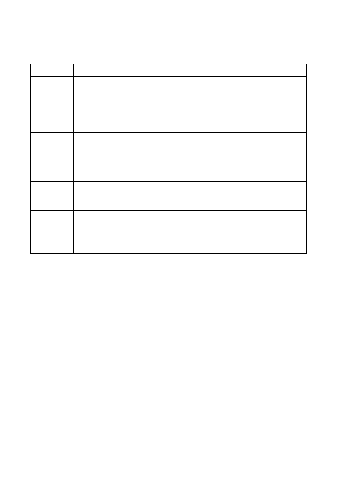
Process Time (sec.)
Zone 1 Pre-rinse, external, cold, 10 –15°C 45
Washing, acidic, external 35°C 120
Draining time 10
Re-rinse, external approx. 80°C *10
Draining time *15
Re-rinse, external approx. 80°C *15
Draining time 15
Zone 2 Washing, alkaline, external, 93°C 135
Draining time 10
Re-rinse, external, acidic, 90°C 10
Draining time 15
Re-rinse, external 90°C 15
Draining time 15
Zone 3 Drying, external 100 –120°C 200
Zone 4 Drying, external 100 –120°C 200
Door open / close & transport 60
(sluice discharge)
Cycle time overall ca. 290
≈5 minutes
* When occupying the disinfection zone (washing zone 2), the re-rinse and draining times will depend on the
respective objects being washed therein!
Sterilisation
Only previously cleaned and disinfected handles may be sterilised.
The handles are placed in a suitable sterilisation pack (one-way sterilisation pack, e.g. foil / paper
sterilisation bags, single or double pack) in accordance with DIN EN 868 / ISO 11607 for steam sterilisation
and then sterilised.
Use only the sterilisation procedure listed below for sterilisation. Other sterilisation procedures (e.g.
ethylene oxide, formaldehyde and low-temperature plasma sterilisation) are not permissible.
Steam sterilisation procedure
Validated in accordance with DIN EN 554/ISO 11134
Maximum sterilisation temperature 134°C
Proof in principle of the handles’ suitability for effective sterilisation was provided using a fractional vacuum
process (Euroselectomat 666 by MMM Münchner Medizin Mechanik GmbH, sterilising temperature 134°C,
holding time 7 min.)
Inspection / durability
The handles should be inspected for damage and changed before re-use, if required.
The handles may be cleaned / disinfected, sterilised and re-used for a maximum of 1000 times. If the
handles are re-used more than 1000 times, then this will be the responsibility of the hospital / clinic.

Quintaflex R96 Ceiling, Wall Model Dr. Mach
Lamps and Engineering
59250001 Edition 01
21.02.2002 / Bak Page
11/18
3.2 Lamp head, splinter protection disk
The lamp head 2has a high quality surface, which
can be cleaned with conventional cleaning agents.
The splinter protection disks 3are made of a high
quality plastic. Pay attention to the following during
cleaning:
•Wipe the splinter protection disks 3always with
a wet cloth. Do not wipe dry!
•Only use disinfectant with less than 20%
alcohol.
After cleaning wipe the splinter protection disks 3
with an antistatic, non-fluffy cloth.
Alc. ≤20 %
2
3

Quintaflex R96 Ceiling, Wall Model Dr. Mach
Lamps and Engineering
59250001 Edition 01
21.02.2002 / Bak Page
12/18
4. Maintenance
The lamp has been designed and built so that regular maintenance intervals are not necessary.
In order to keep the system easy running throughout its life span, we recommend that the hinges be
greased once a year with an acid-free grease.
4.1 Adjustments at the ceiling
attachment
♦Adjusting the spring arm
Note:
Maximum additional load at spring arms: Spring
arms are equipped with different springs to
compensate the lamp / device weight.
To adjust the spring force make sure that the spring
arm with the lamp / device can come to rest in any
desired position.
•A hole 1
is located at the position marked by
detail X.
•Position the spring arm 2
with the lamp / device
approximately 10° above horizontal.
•
Insert Allan key (width 5, included in the scope
of supply) into the hole 1.
If the spring arm drops, the spring force is too low:
-Rotate the adjustment screw to the left (coun
ter
clockwise) in the +direction.
If the spring arm rises, the spring force is too high:
-Rotate the adjustment screw to the right
(clockwise) in the -direction.
If the spring arm w
ith the lamp / device cannot
come to rest in any desired position after the
spring force has been adjusted, the springs must
be replaced by a service technician.
10°
-
+
2
1
X
Hole 1
Width 5

Quintaflex R96 Ceiling, Wall Model Dr. Mach
Lamps and Engineering
59250001 Edition 01
21.02.2002 / Bak Page
13/18
♦Adjusting the central spring arm
To adjust the spring force make sure
that the
spring arm with the lamp / device can come to
rest in any desired position.
•Insert the Allan key width 5 in the hole 6.
If the spring arm drops, the spring force is too low:
-
Rotate the adjustment screw to the left (counter
clockwise) in the +direction.
If the spring arm rises, the spring force is too high:
-
Rotate the adjustment screw to the right
(clockwise) in the -direction.
If the spring arm with the lamp / device cannot
come to rest in any desired position after the
spring force has been
adjusted, the springs must
be replaced by a service technician.
-
+
3
Hole 3
Width 5

Quintaflex R96 Ceiling, Wall Model Dr. Mach
Lamps and Engineering
59250001 Edition 01
21.02.2002 / Bak Page
14/18
4.2 Adjustments at the lamp head
♦Adjusting the lamp bow
For adjusting the lamp bow proceed as follows:
•Turn off the lamp.
•Loosen the countersunk screws 1(covered by
seal 4) using a cross screw driver and carefully
lift the upper housing part off the seal.
•Screw the nuts 2on both sides a little tighter
using an open-ended or ring wrench SW14, or
loosen these nuts while at the same time holding
the screw slot 3in each case with a screw
driver.
•Once the adjustment has been made, place seal
4correctly on the housing lower part.
•Replace the upper part of the lamp housing, so
that the seal lies cleanly around the
circumference.
•Using a round object (drawing pin or small screw
driver), lift the seal and lower the lamp housing
upper part until it sits evenly around the whole
circumference.
•Tighten using the countersunk screws 1.
•Press into place seal 4where widened.
1
4
3
2
1
1

Quintaflex R96 Ceiling, Wall Model Dr. Mach
Lamps and Engineering
59250001 Edition 01
21.02.2002 / Bak Page
15/18
4.3 Changing of spare parts
4.3.1 Changing the halogen bulbs
Dr. Mach uses special halogen bulbs as illuminants.
Only original Dr. Mach replacement bulbs may
be used.
The use of other bulbs can lead to a considerable
reduction of the light power and increase in the
thermal load.
To change the halogen bulbs proceed as follows:
•Turn off the lamp.
•Rotate the three quick-release fasteners 1
half a
turn anticlockwise so that the corresponding disk
bearer can be removed from the bottom part of
the lamp housing.
•Press outward security clip 2and turn shade-
holder 3down.
•Carefully remove the halogen bulb 4(22,8-
24V/
50W) from its socket, change and replace.
•
Replace shadeholder and the disk bearer onto
the bottom part of the lamp housing and rotate
the quick-release fasteners 1clockwise.
Do not touch the halogen bulb with naked
hands.
Remove stains with a clean cloth and alcohol,
since otherwise these can burn into the glass
and lead to early failures.
Remark:
The halogen bulbs have a service life of
approx. 1000 hours without any deterioration
in their luminosity.
If after approx. ½ year of average use of eight hours
daily one of the halogen bulbs should fail, we
recommend that the whole set should be replaced.
4.3.2 Changing the fuses
The necessary fuses are provided by the customer.
Pay attention to the instructions from the local
installer!
2
3
4
1

Quintaflex R96 Ceiling, Wall Model Dr. Mach
Lamps and Engineering
59250001 Edition 01
21.02.2002 / Bak Page
16/18
4.3.3 Changing the filter disk
The dielectric filter disk between reflector and splinter
protection disk prevents a damaging heating of the
illuminated area.
The lamp may not be used without this filter.
For changing the filter disk proceed as follows:
•Turn off the lamp.
•Rotate the three quick-release fasteners 1half a
turn anticlockwise so that the corresponding disk
bearer can be removed from the bottom part of
the lamp housing.
•Slightly loosen nuts 2, carefully bend the
retaining springs 3apart, change and replace the
filter disk 4.
Only use filter disks which have been
cleaned accordingly.
4.3.4 Changing the splinter protection
disk
In case you notice a reduced light quality because of
a dull splinter protection disk, it may be necessary to
change the disk.
To change the splinter protection disk proceed as
follows:
•Turn off the lamp.
•Rotate the three quick-release fasteners 1half a
turn anticlockwise so that the corresponding disk
bearer can be removed from the bottom part of
the lamp housing.
•Remove filter disk 4as described at point 4.3.3.
•Loosen the three nuts 2M3, remove retaining
spring 3and retaining ring 5.
•Change and replace splinter protection disk 6
and lay stay tube 7, retaining ring and retaining
spring in the correct order on the disk bearer
according to the illustration.
•Place nuts 2onto the threaded bolts according
to the illustration and tighten.
•Carefully bend the retaining springs 3apart and
replace filter disk.
Only use filter disks which have been
cleaned accordingly.
•Replace disk bearer and fasten by turning the
three quick-release fasteners 1.
4
4
2
3
5
6
7
1

Quintaflex R96 Ceiling, Wall Model Dr. Mach
Lamps and Engineering
59250001 Edition 01
21.02.2002 / Bak Page
17/18
5. Data
5.1 Technical data
alternating current
rated voltage
rated current
frequency Hertz
fuse
class of protection
5.2 Environmental conditions
Operation
Min. Max.
Temperature +10°C +40°C
Relative atmospheric
humidity 30% 75%
Air pressure 700 hPa 1060 hPa
Transport / Storage
Min. Max.
Temperature -10°C +50°C
Relative atmospheric
humidity 20% 90%
Air pressure 700 hPa 1060 hPa

Quintaflex R96 Ceiling, Wall Model Dr. Mach
Lamps and Engineering
59250001 Edition 01
21.02.2002 / Bak Page
18/18
6. Marking
6.1 Specification of bulb
voltage, power
socket
mode of operation
6.2 CE-mark
The products Quintaflex R96 comply to the standards 93/42/EEC for medical products of the
European Community’s Council.
7. Disposal
The OT-lamp Quintaflex R96 does not contain any danger goods.
The components of the OT-lamp should be properly disposed at the end of their shelf life.
Make sure that the materials are separated accordingly.
For disposal proceed as follows:
•PC-boards should be submitted to an appropriate recycling.
•The rest of the components should be disposed according to the contained materials.

Quintaflex R96 Ceiling, Wall Model Dr. Mach
Lamps and Engineering
59250001 Edition 01
21.02.2002 / Bak Page
19/18
8.Spare parts
Power supply with 24V –ceiling model

Quintaflex R96 Ceiling, Wall Model Dr. Mach
Lamps and Engineering
59250001 Edition 01
21.02.2002 / Bak Page
20/18
9.Spare part list
Item
Qty.
Name EDVNO Remarks
01 1 Lamp bow, complete 25100001
02
03 2 Sliding contact -connector 07102001 1x in 1 and 25 or 26
04 1 Bolt 22080203
05 2 Corrugated washer 65542002
06 2 Pressure washer 07011204
07 2 Hexagonal nut M10x1 DIN 439 67900001
08 1 Sterilizable handle sleeve 21150002
09
10 1 Handle coupling 23052001
11
12
13 1 Seal 25000201
14 1 Housing lower part 25012003
15 2 Bolt, complete 23082202
16
17 1 Housing upper part 25011001
18 2 Countersunk screw for att. the housing upper part 65102005
19 5 Reflector, complete 25060002
20
21 5 Glass reflector 10060201
22 5 Flange23060208
23 5 Cooling body 23060214
24 1 Handle bow, complete 25040001
25 1 Cardan bow, complete 25110001
26
27 1 Inner ring for needle bearing in part 25/26 23110202
28
29
30 5 Socket 67320005
31 5 Halogen bulb 22,8V/50W 67100201
32 5 Tracer pin 25080202
33
34 1 Focussing gear, complete 25050001
35 1 Housing 25050201
36 1 Cap 25054001
37 1 Centring disc 25053202
38 1 Gear set 25055202
39 5 Segment with inner contour 25080206
40 5 Link with screw thread 25080208
41 5 Link without screw thread 25080207
42 5 Support 25080204
43
44 5 Disc bearer, complete 23160002
45 5 Disc bearer ring with quick-release fastener 23161001
46 15 Tubular rivet 65702003
47 5 Splinter protection disc 23200201
48 5 Dielectric filter disc 23250201
49 5 Retaining ring 23160205
50 15 Retaining spring 23160202
This manual suits for next models
2
Table of contents
Other Dr. Mach Lighting Equipment manuals