Dr. Mach Mach 120F User manual

MACH 120F/120
Ceiling, Wall, Stand model
Dr. Mach
Lamps and Engineering
59080001 Edition 08 06.02.2010 / Bak Page 1/19
Instructions for use
MACH 120F/120
Ceiling, Wall, new-type stand model
Mach 120F ceiling lamp ____________________________Order No. 1202 2033 30
Mach 120 ceiling lamp _____________________________Order No. 1201 1033 30
Mach 120F wall lamp ______________________________Order No. 1202 2022 02
Mach 120 wall lamp _______________________________Order No. 1201 1022 02
Mach 120F, new-type stand model ___________________Order No. 1202 2013 00
Mach 120, new-type stand model ____________________Order No. 1201 1013 00
Dr. Mach
GmbH u. Co. KG, Flossmannstrasse 28, D-85560 Ebersberg
Tel.: +49 (0)8092 2093 0, Fax +49 (0)8092 2093 50
Internet: www.dr-mach.com, E-mail: info@dr-mach.de

MACH 120F/120
Ceiling, Wall, Stand model
Dr. Mach
Lamps and Engineering
59080001 Edition 08 06.02.2010 / Bak Page 2/19
List of contents
1. Safety instructions ........................................................................................ Page 3
2. Operating the lamp Mach 120F/120.............................................................. Page 4
2.1 ON/OFF switch....................................................................................... Page 4
2.2 Positioning.............................................................................................. Page 4
2.3 Light field adjustment (focusing)............................................................. Page 4
3. Cleaning ....................................................................................................... Page 5
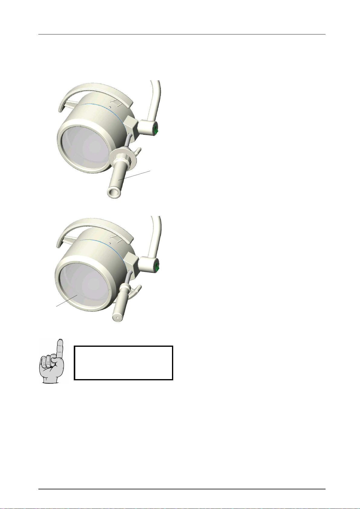
3.1 Sterilisable handle .................................................................................. Page 5
3.2 Lamp head, protective disk..................................................................... Page 5
4. Maintenance................................................................................................. Page 6
4.1 Adjustments at the ceiling/wall attachment and new-type stand.............. Page 6
4.2 Adjustments at the lamp head ................................................................ Page 6
4.3 Changing of spare parts ......................................................................... Page 7
4.3.1 Changing the halogen bulbs.............................................................. Page 7
4.3.2 Changing the fuses............................................................................ Page 7
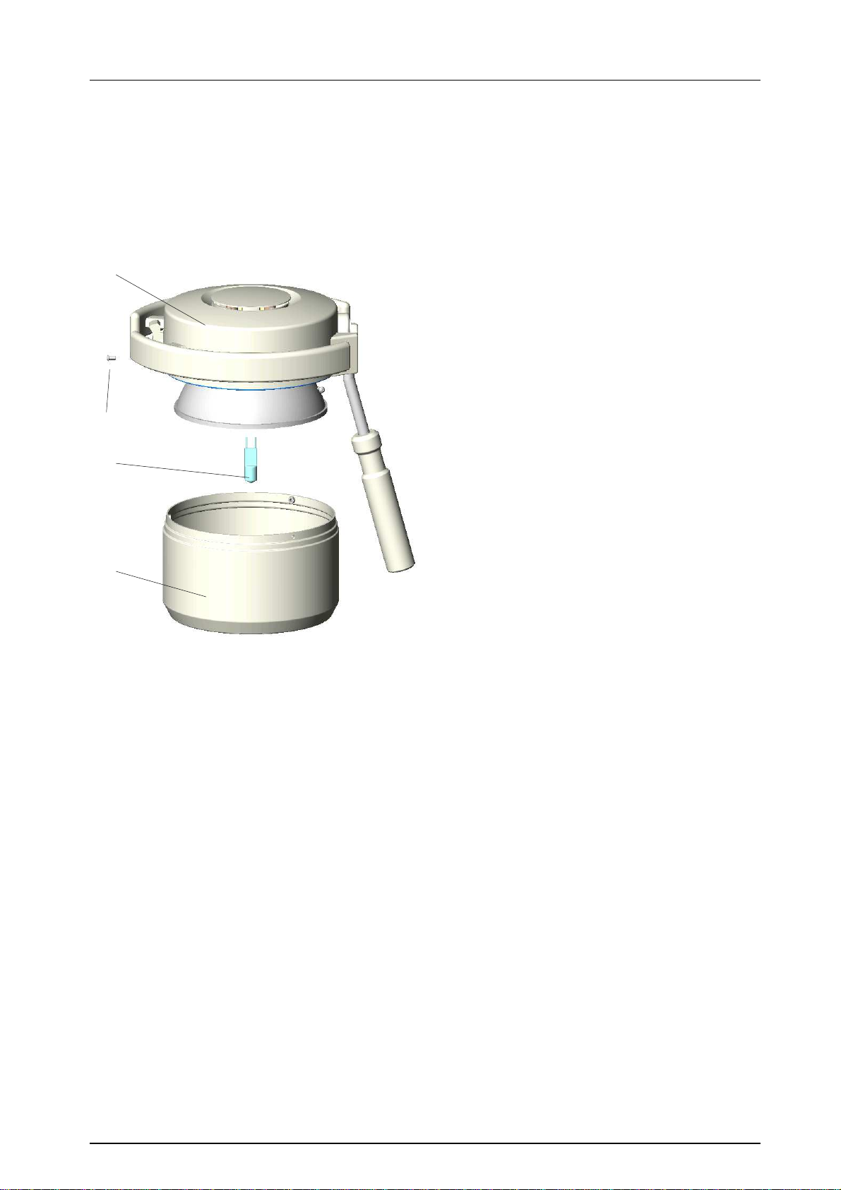
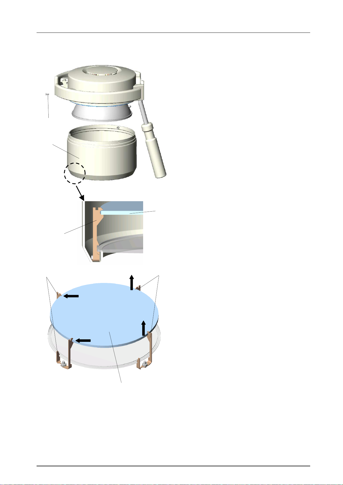
4.3.3 Changing the protective disk ............................................................. Page 8
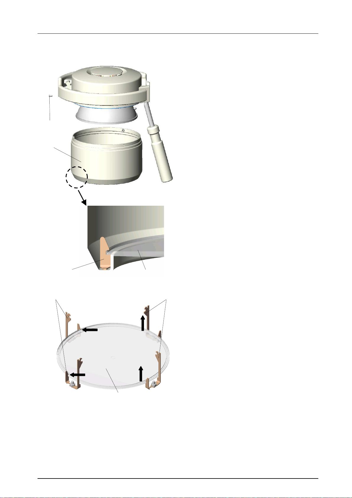
4.3.4 Changing the filter disk...................................................................... Page 9
4.3.5 Conversion to sterilisable handle....................................................... Page 10
5. Data.............................................................................................................. Page 11
5.1 Technical data........................................................................................ Page 11
5.2 Environmental conditions........................................................................ Page 11
6. Characteristics.............................................................................................. Page 11
6.1 Specification of bulb................................................................................ Page 11
6.2 Specification of fuse................................................................................ Page 12
6.3 CE-mark................................................................................................. Page 12
7. Disposal........................................................................................................ Page 12
8. Spare parts................................................................................................... Page 13
8.1 Mach 120F ceiling/wall/stand model ....................................................... Page 13
8.2 Mach 120 ceiling/wall/stand model.......................................................... Page 14
8.3 Spare parts list........................................................................................ Page 15
9. Electromagnetic compatibility ....................................................................... Page 17

MACH 120F/120
Ceiling, Wall, Stand model
Dr. Mach
Lamps and Engineering
59080001 Edition 08 06.02.2010 / Bak Page 3/19
1. Safety instructions
Please pay attention to the directions for use when handling the lamp.
Attention:
This device is not suitable for use in hazardous locations. The lamp is classified
As a Group 1 device according to the MedGV (Medical Ordinance).
Repairs to the lamp and special installation work on the reflector or plug-in socket should
only be carried out by ourselves or a company expressly authorised by ourselves.
The manufacturer is only responsible for the safety of the lamp if repairs and alterations have
been carried out by themselves or a company who can guarantee that the safety regulations
have been observed.
The manufacturer is not liable for personal or material damages if the lamp is misappropri-
ately or incorrectly operated or misused.
The lamp body may only be dismantled from the swivel arm in reverse order of its assembly.
Make sure that the lamp is in perfect working order before every use.

MACH 120F/120
Ceiling, Wall, Stand model
Dr. Mach
Lamps and Engineering
59080001 Edition 08 06.02.2010 / Bak Page 4/19
2. Operating the lamp Mach 120F/120
There are two types of Mach 120F/120 -lamps
available:
• Mach 120F with focusable light field and dielec-
tric light system Ra=93
• Mach 120 with fix-focus and standard light sys-
tem Ra=86
The lamp types are equipped with an external
transformer:
• Mach 120F/120, voltage 22,8V / external trans-
former.
2.1 ON/OFF switch
The switch 37 with signal lamp at the lamp bow
turns the lamp on and off.
Because of the external transformer of the lamps,
in addition to the switch 37 a two-pole switch
ON/OFF must be provided by the customer.
2.2 Positioning
Use the handle 17/50 or the handle rail GL to posi-
tion the lamp.
There are two handle types available:
• Handle 17
The handle 17 is fixed to the handle bar 16 and
can be removed.
• Sterilizable handle 50
The sterilizable handle can be removed for ster-
ilisation. It is fixed by the couple to the handle
bar 16.
2.3 Light field adjustment
- focusing (Mach120F only)
The lamp models Mach 120F have a focusing func-
tion. That means, you can either enlarge the di-
ameter of the light field or bundle the light to a
smaller area, depending on the circumstances.
To activate the focusing function, move lever 08 at
the lamp head up and down (see figure).
37
GL
16
49
17
50
08

MACH 120F/120
Ceiling, Wall, Stand model
Dr. Mach
Lamps and Engineering
59080001 Edition 08 06.02.2010 / Bak Page 5/19
3. Cleaning
3.1 Sterilisable handle
The lamps Mach 120F/120 can be equipped as an
option with a sterilisable handle 50.
The sterilisable handle 50 can be removed and
sterilised at temperatures up to a max. of 134°C.
No other parts may touch the handle during sterili-
sation. The handle should be placed in a vertical
position during sterilisation.
3.2 Lamp head, protective disk
The lamp has a high-quality surface, which can be
cleaned with conventional cleaning agents.
The protective disk 15 is made of an high-quality
plastic. Pay attention to the following during clean-
ing:
-
Wipe over the disk 15 with a wet cloth (never
use a dry cloth!).
-
Only use disinfectant with less then 20% alcohol.
Wipe the disk 15 after cleaning with an antistatic,
non-fluffy cloth.
Alc. ≤
≤≤
≤20 %
50
15

MACH 120F/120
Ceiling, Wall, Stand model
Dr. Mach
Lamps and Engineering
59080001 Edition 08 06.02.2010 / Bak Page 6/19
4. Maintenance
Maintenance and inspection of the light should be done every two years.
In order to keep the system easy-running throughout its life span, we recommend that the hinges should be
greased once a year with acid-free grease.
Maintenance and safety check duties:
- Visual inspection
- Complete check of the ceiling or wall attachment
- Changing the halogen bulbs, if necessary
- Protective conductor resistance measurement
- Leakage current measurement
- Insulation resistance measurement, if necessary
- Functional testing
- Electrical safety check
- Light intensity measurement
- Completing the test report
4.1 Adjustments at the ceiling/wall
attachment and new-type stand
♦ Adjusting the spring arm
(new-type attachment)
To adjust the spring force proceed as follows:
a) The spring arm moves down on its own:
• Pull the lamp head approx. 20°downwards until
drilled hole B lies on the upper side of the joint
between spring arm and horizontal arm and a
screw is visible in the hole.
• Insert a slotted screw driver into drilled hole B.
• Turn adjusting screw to the left (anticlockwise),
the spring force increases.
b) The spring arm moves up on its own:
• Pull the lamp head approx. 20°downwards until
drilled hole B lies on the upper side of the joint
between spring arm and horizontal arm and a
screw is visible in the hole.
• Insert a slotted screw driver into drilled hole B.
Turn adjusting screw to the right (clockwise),
the spring force decreases.
4.2 Adjustments at the lamp head
♦ Manipulating the lamp
The lamp bow 32 enables a perfect movability and
positioning of the lamps Mach 120F/120.
The brake force in the axis Ais set. It is usually not
necessary to adjust it.
20°
B
32
A

MACH 120F/120
Ceiling, Wall, Stand model
Dr. Mach
Lamps and Engineering
59080001 Edition 08 06.02.2010 / Bak Page 7/19
4.3 Changing of spare parts
4.3.1 Changing the halogen bulbs
Dr. Mach uses special halogen bulbs as illuminants.
Only original Dr. Mach replacement bulbs may
be used.
The use of other bulbs can lead to a considerable
reduction of the light power and increase in the
thermal load.
To change the bulbs proceed as follows:
• Attention!! Turn off the lamp!
• Loosen three screws 27 at the base frame 01.
• Remove housing lower part 02 by pulling it
downwards.
Attention! If the bulb is changed immediately
after operating the lamp, some parts of the lamp
may be hot.
Do not touch the halogen bulb with naked
hands.
• Draw halogen bulb 11 (22,8-24V/50W) carefully
from its socket.
• Put in the new halogen bulb.
• Mount the housing lower part 02 in reverse order
of dismounting it.
Remark:
The halogen bulbs have a service life of approx.
1000 hours without any deterioration in their
luminosity.
4.3.2 Changing the fuses
Because of the external transformer of the Mach
120 lamps, the necessary fuses must be provided
by the customer.
Pay attention to the instructions from the local
installer.
01
27
11
02

MACH 120F/120
Ceiling, Wall, Stand model
Dr. Mach
Lamps and Engineering
59080001 Edition 08 06.02.2010 / Bak Page 8/19
4.3.3 Changing the filter disk
The filter disk between reflector and protective disk
(Mach 120F only) prevents a damaging heating of
the illuminated area.
ATTENTION!
The lamps may not be used without this filter.
To change the filter disk 55 proceed as follows:
• Attention!! Turn off the lamp!
• Remove housing lower part 02 as described at
point 4.3.1.
The filter disk 55 is held by the 4 springs (holders)
54.
• Press the filter disk 55 carefully against 2 springs
54a (I.) and lift it off the other 2 springs 54b (II.).
• Insert the new filter disk in reverse order.
Only use filter disks that have been cleaned
properly.
• Fix the housing lower part 02 as described at
point 4.3.1.
02
27
54
55
54a
54b
I.
I.
II.
II.
55

MACH 120F/120
Ceiling, Wall, Stand model
Dr. Mach
Lamps and Engineering
59080001 Edition 08 06.02.2010 / Bak Page 9/19
4.3.4 Changing the protective disk
In case you notice a impediment of the light quality
because of a dull protective disk, it may be neces-
sary to change the disk.
To change the disk proceed as follows:
• Attention!! Turn off the lamp!
• Remove housing lower part 02 as described at
point 4.3.1.
The protective disk 15 is held by the four springs
(holders) 13.
• Press the protective disk 15 against 2 springs 13a
( I. ) and lift it off the other two springs 13b ( II. ).
• Insert the new protective disk in reverse order.
Attention: Only use protective disks, that
have been cleaned properly.
• Fix the housing lower part 02 as described at
point 4.3.1.
02
27
13
15
13a
13b
15
I.
I.
II.
II.

MACH 120F/120
Ceiling, Wall, Stand model
Dr. Mach
Lamps and Engineering
59080001 Edition 08 06.02.2010 / Bak Page 10/19
4.3.5 Conversion to sterilisable handle
Extent of supply:
− sterilisable handle sleeve
− couple
− one screw M4x35 DIN 912:A2 with safety lake
• Turn off the lamp.
• Remove covering cap 18 with a screw driver.
• Loosen the screw SM4x6 DIN 7985 with a
cross screw driver.
• Remove screw SM4x6 DIN 7985 and lock
washer ZS ∅4,3 DIN 6797.
• Hold the handle, while removing the screw and
the lock washer, to ensure no damaging in the
lamp housing.
• Remove handle 17 by using a plastic hammer
(see arrow in figure).
• Put couple 49 on the handle bar 16.
• Fix couple 49 with the screw S1 M4x35 DIN
912:A2 with safety lake.
• Push the sterilizable handle sleeve on the cou-
ple 49, so that it is secured by push-button DK.
16
ZS
S
17
18
16
DK
49
S1
Plastic hammer

MACH 120F/120
Ceiling, Wall, Stand model
Dr. Mach
Lamps and Engineering
59080001 Edition 08 06.02.2010 / Bak Page 11/19
5. Data
5.1 Technical data
Mach 120F/120 design with 22,8 Volt
~ Wechselstrom alternating current
Pr Primärseitig 230V / 0,22A primary side
Sek Sekundärseitig 22,8V / 2,20A secondary side
Leistungsaufnahme 50VA power consumption
Hz Hertz-Frequenz 50 / 60Hz frequency Hertz
Sicherung fuse
Schutzgrad Type „B“ class of protection
5.2 Environmental conditions
Operation
Min. Max.
Temperature +10°C +40°C
Relative atmospheric humidity 30% 75%
Air pressure 700 hPa 1060 hPa
Transport / storage
Min. Max.
Temperature -10°C +50°C
Relative atmospheric humidity 20% 90%
Air pressure 700 hPa 1060 hPa
6. Characteristics
6.1 Specification of bulb
voltage, power
socket
mode of operation
Attention!
Beginning with the serial number 09/04179, manufacturing date 20th may 2009, the lights
Mach 120 / 120F are equipped with halogen bulbs 22,8V / 50W.
22,8V 50W
G 6,35
HALOGEN

MACH 120F/120
Ceiling, Wall, Stand model
Dr. Mach
Lamps and Engineering
59080001 Edition 08 06.02.2010 / Bak Page 12/19
Attention!
Beginning with January 15th 2010 the formerly known verification document is no longer
delivered with the light. This document can be requested when needed. Please provide
the serial number of respective light.
The light must still be tested at commissioning.
6.2 Specification of fuse
Design with 22,8 Volt
Because of the external transformer there are no fuses in the lamp head. When installing the lamp, the
fuses must be provided by the customer.
6.3 CE-mark
The products Mach 120F/120 comply to the standards 93/42/EEC for medical products of
the European Community’s Council.
7. Disposal
The components of the lamp should be properly disposed at the end of its shelf-life.
Make sure, that the materials are carefully separated.
The lamp does not contain any danger goods. The components should be disposed according to the con-
tained materials.

MACH 120F/120
Ceiling, Wall, Stand model
Dr. Mach
Lamps and Engineering
59080001 Edition 08 06.02.2010 / Bak Page 13/19
8. Spare parts
8.1 Mach 120F ceiling/wall model
11 12
10
54,14
15 55
38
01
02
03 33,34,39
04 05
06
07
08
27
09
12
16
19
22
23,24,25,26
32
49
35,36
37
55 15 20,21
17
54
28,29

MACH 120F/120
Ceiling, Wall, Stand model
Dr. Mach
Lamps and Engineering
59080001 Edition 08 06.02.2010 / Bak Page 14/19
8.2 Mach 120 ceiling/wall model
11 51
38
10
01
02
03 33,34,39
04 05
27
51 15
16
19
22
23,24,25,26
32
49
35,36
37
53
52
56
28,29
54,14
15 56
20,21
54
17

MACH 120F/120
Ceiling, Wall, Stand model
Dr. Mach
Lamps and Engineering
59080001 Edition 08 06.02.2010 / Bak Page 15/19
8.3 Spare parts list
Item
Qty. Name EDVNO Remarks
01 1 Base frame 08030201
02 1 Bottom part of lamp housing 08012003
03 1 Cover 08030304
04 4 Spacer sleeve 08062201
05 8 Self-tapping screw M2,9x9,5 DIN 7981 65132005
06 1 Saddle 08051202 Mach 120F only
07 1 Adjusting lever for focusing 08051201 Mach 120F only
08 1 Lever cap 74012012 Mach 120F only
09 1 Socket for reflector 08051203 Mach 120F only
10 1 Lamp holder 67320001
11 1 Halogen bulb 22,8V/50W 67100201
12 1 Reflector unit Mach 120F (glass reflector) 08060002 Mach 120F only
13 4 Holder 08012204
14 4 Nut M3 DIN 934 65332002
15 1 Protective disk 07200201
16 1 Handle bar 08000204
17 1 Handle 08030305
18 1 Covering cap 08030306
19 2 Screw M3x6 ULF with safety lake 65902003
20 1 Holding plate 08000205
21 4 Self-tapping screw M3,5x13 DIN 7981 65132007
22 1 Brake disk 08000202
23 1 Washer 10030210
24 1 Plate spring DIN 2093 25x12,2x1 65982006
25 1 Rotation block 08000203
26 1 Nut M12x1 67900002
27 3 Screw M3x6 ULF 65902001
28 1 Line clamp 2-pole 07053202
29 2 Self-tapping screw M2,9x16 DIN 7981 65132008
30
31
32 1 Lamp bow 08100001
33 1 Cover 07100201
34 2 Screw M3x8 DIN 966 65112013
35 1 Cover 08100201
36 2 Screw M2,5x6 DIN 966 65112001
37 1 2-pole ON/OFF switch (illuminated) 67340002
38 1 Sliding contact with cable 08102001
39 1 Insulating washer 74012001
40
41
42
43
44
45
46
47
48
49 1 Handle sleeve, sterilizable 72000011
50
51 1 Reflector unit Mach 120 (metal sheet reflector) 08060001 Mach 120 only
52 1 Holding plate 08062002 Mach 120 only

MACH 120F/120
Ceiling, Wall, Stand model
Dr. Mach
Lamps and Engineering
59080001 Edition 08 06.02.2010 / Bak Page 16/19
Pos.
Stck
Benennung EDVNR Bemerkung
53 1 Cover 08030303 Mach 120 only
54 4 Holder (spring) 08012202 Mach 120F only
55 1 Conversion filter D130 Borofloat 67390202 Mach 120F only
56 1 Heat protection filter 07250201 Mach 120 only

MACH 120F/120
Ceiling, Wall, Stand model
Dr. Mach
Lamps and Engineering
59080001 Edition 08 06.02.2010 / Bak Page 17/19
9. Electromagnetic compatibility
Table 201 – Guidance and manufacturer´s declaration – electromagnetic emission – for all EQUIPMENT AND SYSTEMS (see
6.8.3.201 a) 3))
1 Guidance and manufacturer´s declaration – electromagnetic emission
2 The MACH 120 / 120 F is intended for use in the electromagnetic environment specified below. The
customer or the user of the MACH 120 / 120 F should assure that it is used in such an environment.
3 Emissions test Compliance Electromagnetic environment - guidance
7 Harmonic emissions
IEC 61000-3-2 Class C
8 Voltage fluctuations /
flicker emissions
IEC 61000-3-3 Complies
The MACH 120 / 120 F is suitable for use in all
establishments, including domestic establishments and those directly con-
nected to the public low-voltage power supply network that supplies buildings
used for domestic purposes.
12 RF emissions
CISPR 15 Complies The MACH 120 / 120 F is not suitable for interconnection
with other equipment.
Table 202 – Guidance and manufacturer's declaration – electromagnetic immunity – for all EQUIPMENT and SYSTEMS (see
6.8.3.201 a) 6))
Guidance and manufacturer´s declaration – electromagnetic immunity
The MACH 120 / 120 F is intended for use in the electromagnetic environment specified below. The customer
or the user of the MACH 120 / 120 F should assure that it is used in such an environment.
Immunity test IEC 60601
test level Compliance level Electromagnetic environment -
guidance
Electrostatic
discharge (ESD)
IEC 61000-4-2
± 6 kV contact
± 8 kV air ± 6 kV contact
± 8 kV air
Floors should be wood, concrete or
ceramic tile. If floors are covered with
synthetic material, the relative humidity
should be at least 30 %.
Electrical fast
transient / burst
IEC 61000-4-4
± 2 kV for power
supply lines
± 1 kV for input/output lines
± 2 kV for power
supply lines
not applicable
Mains power quality should be that of a
typical commercial or hospital
environment.
Surge
IEC 61000-4-5
± 1 kV differential
mode
± 2 kV common mode
± 1 kV differential
mode
± 2 kV common mode
Mains power quality should be that of a
typical commercial or hospital
environment.
Voltage dips, short
interruptions and
voltage variations
on power supply
input lines
IEC 61000-4-11
< 5 % U
T
(>95 % dip in U
T
)
for 0,5 cycle
40 % U
T
(60 % dip in U
T
)
for 5 cycles
70 % U
T
(30 % dip in U
T
)
for 25 cycles
< 5 % U
T
(>95 % dip in U
T
)
for 5 sec
< 5 % U
T
(>95 % dip in U
T
)
for 0,5 cycle
40 % U
T
(60 % dip in U
T
)
for 5 cycles
70 % U
T
(30 % dip in U
T
)
for 25 cycles
< 5 % U
T
(>95 % dip in U
T
)
for 5 sec
Mains power quality should be that of a
typical commercial or hospital environment. If
the user of the
MACH 120 / 120 F requires
continued operation during power
mains interruptions, it is recommended
that the MACH 120 / 120 F be powered from
an uninterruptible power supply or a battery.
Power frequency
(50/60 Hz)
magnetic field
IEC 61000-4-8
3 A/m 30 A/m Power frequency magnetic fields should be at
levels characteristic of a typical location in a
typical commercial or hospital environment.
NOTE U
T
is the a. c. mains voltage prior to application of the test level.

MACH 120F/120
Ceiling, Wall, Stand model
Dr. Mach
Lamps and Engineering
59080001 Edition 08 06.02.2010 / Bak Page 18/19
Table 204 – Guidance and manufacturer´s declaration – electromagnetic immunity –
for EQUIPMENT and SYSTEM that are not LIFE-SUPPORTING (see 6.8.3.201 b))
Guidance and manufacturer´s declaration – electromagnetic immunity
The MACH 120 / 120 F is intended for use in the electromagnetic environment specified below. The customer
or the user of the MACH 120 / 120 F should assure that it is used in such an environment.
Immunity test IEC 60601 test level Compliance level Electromagnetic environment - guidance
Conducted RF
IEC 61000-4-6
Radiated RF
IEC 61000-4-3
3 V
150 kHz to 80 MHz
3 V/m
80 MHz to 2,5 GHz
3 V
3 V/m
Portable and mobile RF communications equipment should
be used no closer to any part of the MACH 120 / 120 F,
including cables, than the recommended separation dis-
tance calculated from the equation applicable to the fre-
quency of the transmitter.
Recommended separation distance
Pd 17,1=
Pd 17,1=
80 MHz to 800 MHz
Pd 34,2=
800 MHz to 2,5 GHz
where pis the maximum output power rating of the trans-
mitter in watts (W) according to the transmitter manufac-
turer and dis the recommended separation distance in
metres (m).
b
Field strengths from fixed RF transmitters, as determined
by an electromagnetic site survey,
a
should be less than the
compliance level in each frequency range.
b
Interference may occur in the vicinity of equipment marked
with the following symbol:
NOTE 1 At 80 MHz and 800 MHz, the higher frequency range applies.
NOTE 2 These guidelines may not apply in all situations. Electromagnetic is affected by absorption and reflection from structures, objects
and people.
a
Field strengths from fixed transmitters, such as base stations for radio (cellular/cordless) telephones and land mobile radios, amateur
radio, AM and FM radio broadcast and TV broadcast cannot be predicted theoretically with accuracy. To assess the electromagnetic envi-
ronment due to fixed RF transmitters, an electromagnetic site survey should be considered. If the measured field strength in the location in
which the MACH 120 / 120 F is used exceeds the applicable RF compliance level above, the MACH 120 / 120 F should be observed to
verify normal operation. If abnormal performance is observed, additional measures may be necessary, such as reorienting or relocating the
MACH 120 / 120 F.
b
Over the frequency range 150 kHz to 80 MHz, field strengths should be less than 3 V/m.

MACH 120F/120
Ceiling, Wall, Stand model
Dr. Mach
Lamps and Engineering
59080001 Edition 08 06.02.2010 / Bak Page 19/19
Table 206 – Recommended separation distances between portable and mobile
RF communications equipment and the EQUIPMENT or SYSTEM -
for EQUIPMENT and SYSTEMS that are not LIFE-SUPPORTING (see 6.8.3.201 b))
Recommended separation distances between
portable and mobile RF communications equipment and the MACH 120 / 120 F
The MACH 120 / 120 F is intended for use in an electromagnetic environment in which radiated RF disturbances are controlled. The
customer or the user of the MACH 120 / 120 F can help prevent electromagnetic interference by maintaining a minimum distance be-
tween portable and mobile RF communications equipment (transmitters) and the MACH 120 / 120 F as recommended below, according
to the maximum output power of the communications equipment
Separation distance according to frequency of transmitter
m
Rated maximum output
of transmitter
W
150 kHz to 80 MHz
Pd 17,1=
80 MHz to 800 MHz
Pd 17,1=
800 MHz to 2,5 GHz
Pd 34,2=
0,01 0,12 0,12 0,23
0,1 0,37 0,37 0,74
1 1,17 1,17 2,33
10 3,69 3,69 7,38
100 11,67 11,67 23,33
For transmitters rated at a maximum output power not listed above the recommended separation distance d in metres (m) can
be estimated using the equation applicable to the frequency of the transmitter, where P is the maximum output power rating of
the transmitter in watts (W) according to the transmitter manufacturer.
NOTE 1 At 80 MHz and 800 MHz, the separation distance for the higher frequency range applies.
NOTE 2 These guidelines may not apply in all situations. Electromagnetic propagation is affected by absorption and
reflection from structures, objects and people.
This manual suits for next models
1
Table of contents
Other Dr. Mach Medical Equipment manuals

Dr. Mach
Dr. Mach Mach LED 8MC User manual

Dr. Mach
Dr. Mach LED 115 User manual

Dr. Mach
Dr. Mach Mach M2 Series User manual

Dr. Mach
Dr. Mach LED 150 User manual

Dr. Mach
Dr. Mach MACH 120 Series Manual

Dr. Mach
Dr. Mach Mach 400 Manual

Dr. Mach
Dr. Mach Mach LED 2 MC Manual

Dr. Mach
Dr. Mach Trigenflex R96 Manual

Dr. Mach
Dr. Mach LED 6MC User manual

Dr. Mach
Dr. Mach MACH M3 User manual