INTRODUCTION
Corn Head Clinic Guide – Legacy, Series I & II 2
Table of Contents
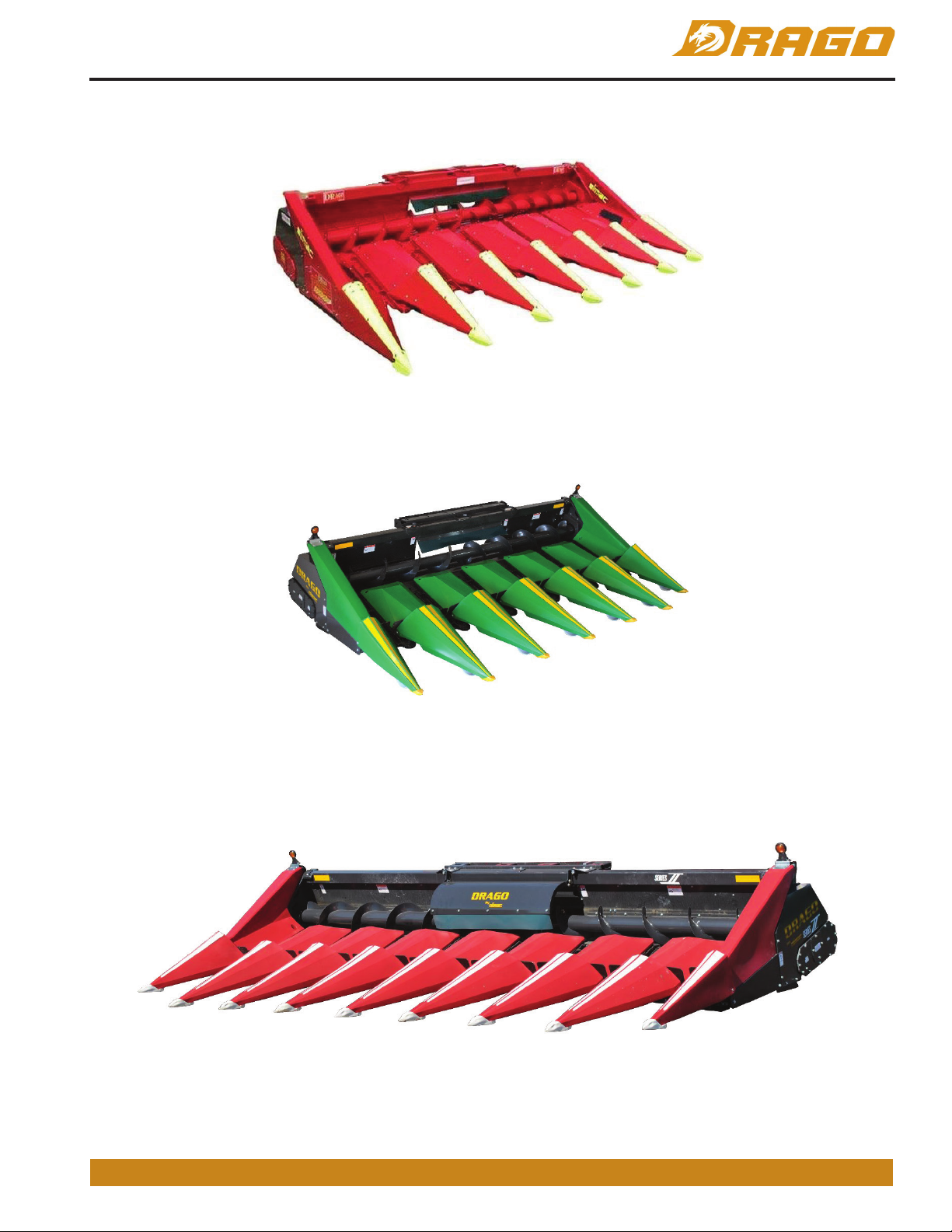
MODEL IDENTIFICATION ......................................................................................................................................... 1
MAINTENANCE ............................................................................................................................................................3
REQUIRED FLUIDS ..................................................................................................................................................... 4
LUBRICANT PART NUMBERS ..................................................................................................................................... 4
MAINTENANCE SCHEDULE ........................................................................................................................................ 5
PRE-SEASON ........................................................................................................................................................... 5
NORMAL OPERATION ............................................................................................................................................. 5
DOWN CORN ........................................................................................................................................................... 6
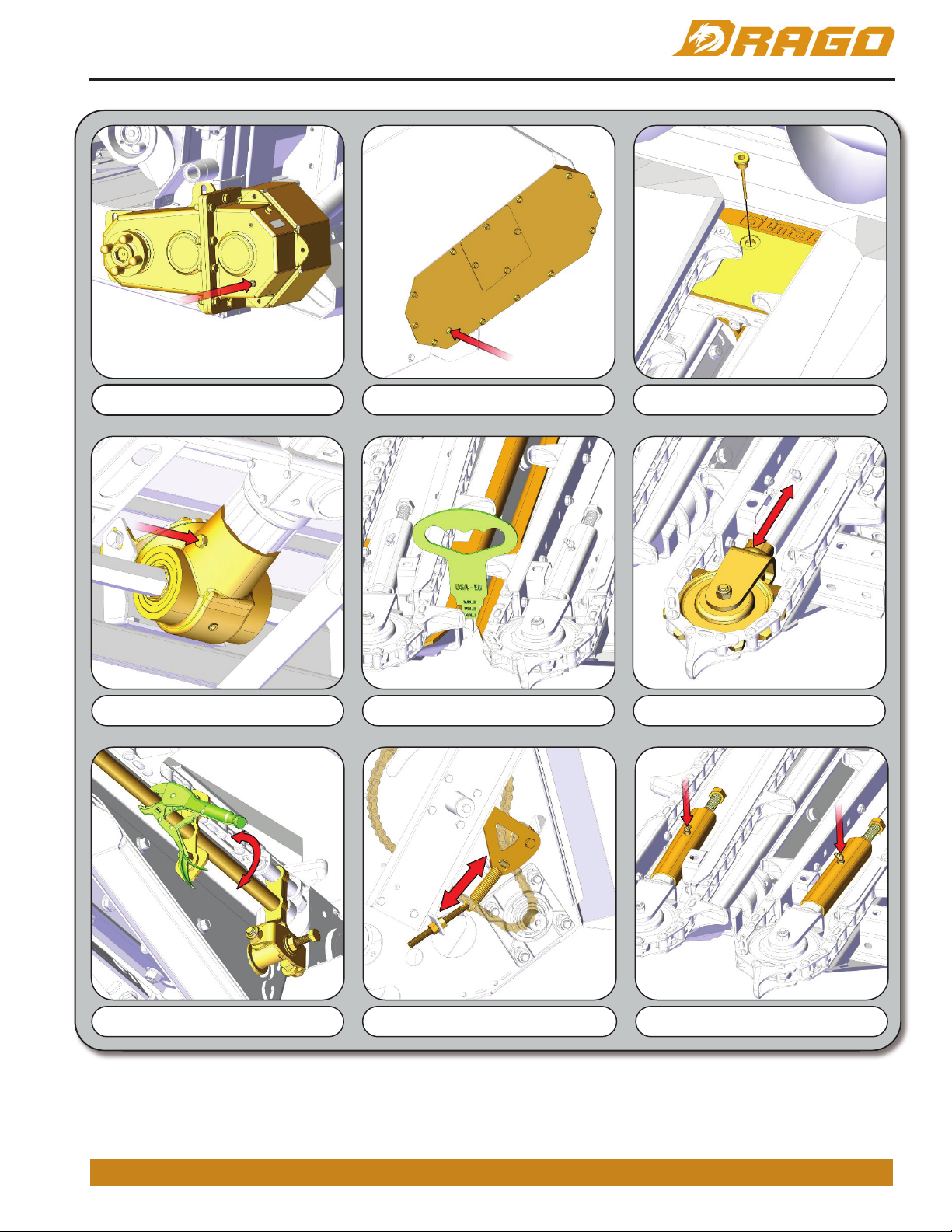
PRE-SEASON ............................................................................................................................................................... 7
20 HOUR ..................................................................................................................................................................... 8
50 HOUR ..................................................................................................................................................................... 8
100 HOUR ................................................................................................................................................................. 10
250 HOUR OR YEARLY ............................................................................................................................................. 10
INITIAL SETTINGS...................................................................................................................................................12
CORN HEAD ANGLE ...................................................................................................................................... 12
HEAD SPEED ................................................................................................................................................ 13
SNOUT ADJUSTMENTS ................................................................................................................................. 14
DECK PLATE GAP ......................................................................................................................................... 14
DECK PLATE TENSION ................................................................................................................................. 15
GATHERING CHAIN TENSION ...................................................................................................................... 15
PART REPLACEMENT .............................................................................................................................................. 16
PERFORMANCE PARTS........................................................................................................................................... 19
TROUBLESHOOTING................................................................................................................................................20
SERVICE VIDEOS ..................................................................................................................................................... 23