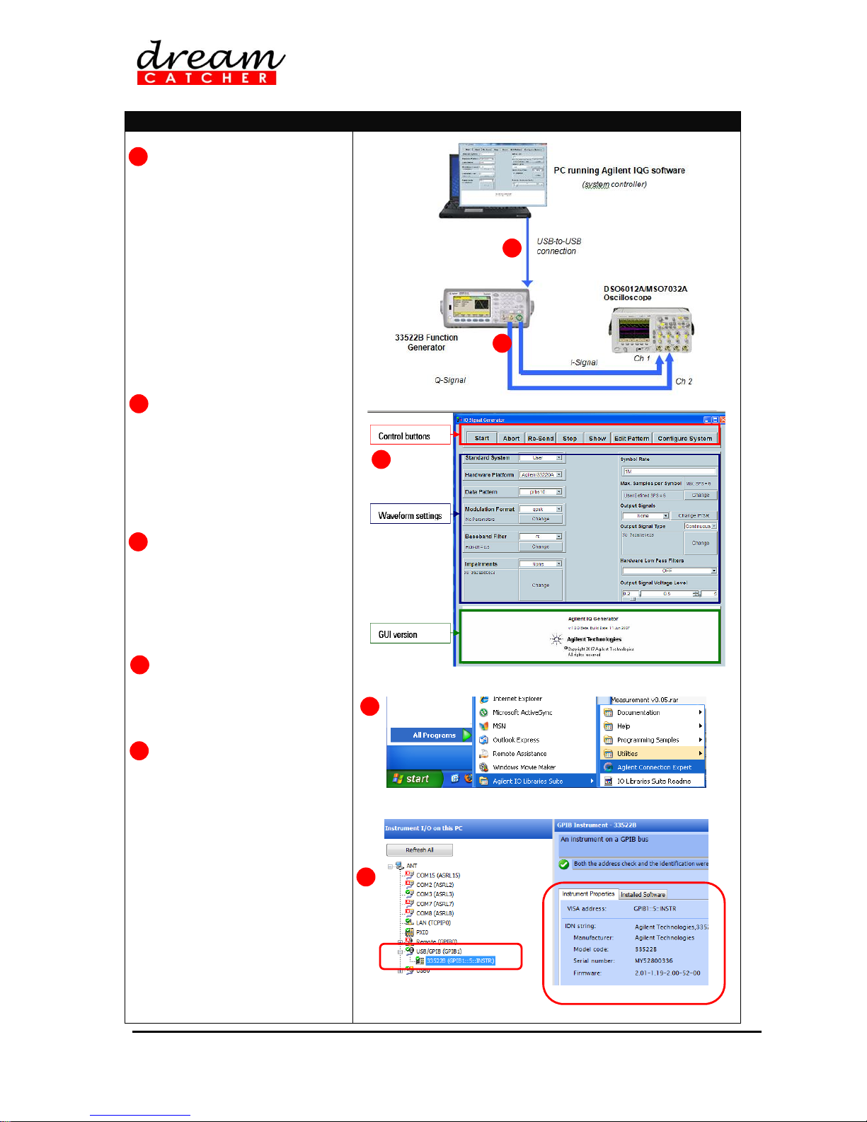
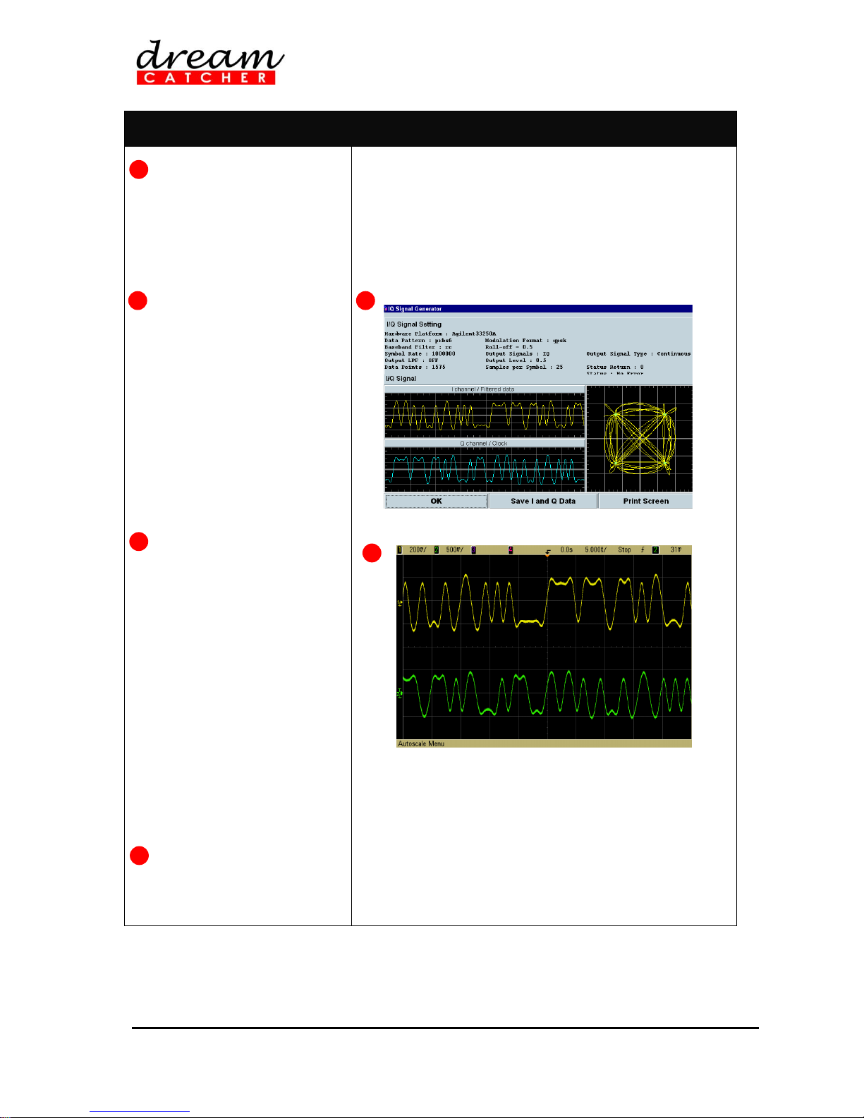
Dream Catcher ME1120 User manual

ME1120 Mobile Communications Courseware
Out-of-Box Teaching Solution for Mobile Communications
Quick Start Guide
version 2.02
Updated on 25 September 2018

ME1120 Mobile Communications
Quick Start Guide - 2/24
NOTE:
This product has been tested and found to conform to the following EMC standards.
The limits are designed to provide reasonable protection against harmful interference
in a laboratory installation.
EMC Standard Limit
CISPR11:1990/EN55011:1991 Group 1, Class A
IEC801-2:1984/EN50082-1:1992 4kV CD, 8kV AD
Safety: IEC61010-1:1990+A1
This product complies with the requirement of the Low Voltage Directive 73/23/EEC
and the EMC Directive 89/336/EEC and carries the CE-marking.
CAUTION –ESD!
THIS PRODUCT CONTAINS ELECTRONIC COMPONENTS SENSITIVE TO
ELECTROSTATIC DISCHARGE.
An electrostatic discharge generated by a person or an object coming in contact with
the electrical components may damage or destroy the product. To avoid the risk of
electrostatic discharge, please observe the handling precautions and
recommendations contained in the EN100015-1 standard. Do not connect or
disconnect the device while it is being energized.
WARNING:
CHANGES OR MODIFICATIONS NOT EXPRESSLY APPROVED BY THE PARTY
RESPONSIBLE FOR COMPLIANCE WITH THE EMC RULES COULD VOID THE
USER’S AUTHORITY TO OPERATE THE PRODUCT.

ME1120 Mobile Communications
Quick Start Guide - 3/24
Table of Contents
Table of Contents....................................................................................................................................3
DreamCatcher Courseware Customer Login Guide...............................................................................5
1. Quick Setup and Verification (33522B Arbitrary Waveform Generator) .............................................7
2. Support and Warranty.......................................................................................................................17
Appendix A: Digital RF Communications Training Kit...........................................................................18
Appendix B: Technical Specifications...................................................................................................19
Appendix C: Recommended Modulation Scheme Settings for IQG Software......................................21
Appendix D: Alternative Setup Using 33220A ......................................................................................22
Revision History....................................................................................................................................23
Contact Us.............................................................................................................................................24

ME1120 Mobile Communications
Quick Start Guide - 4/24

ME1120 Mobile Communications
Quick Start Guide - 5/24
DreamCatcher Courseware Customer Login
Guide
1. Go to the DreamCatcher Courseware website at http://dreamcatcher.asia/cw/
2. Click the Product Registration / Download link at the bottom left corner of the page.
3. If you are new customer, skip to step 5. If you are a returning customer, proceed to step 4.
4. If you are a returning customer, click Continue under the LOGIN section to login.
NOTE: If you have created your DreamCatcher account before the 1st of September 2017,
you will receive an e-mail request to reset your password. If you do not receive the password
reset e-mail within a few minutes of logging in, please check your Junk E-mail folder just in
case the password reset e-mail got delivered there instead of your inbox. Follow the
instructions in the password reset e-mail to reset your password and continue logging in.
Skip to step 6 to complete the log in procedure.
5. If you are a new customer, click Continue under the CREATE ACCOUNT section to create a
new account.
Fill in the New Account form and click SIGN UP to submit your registration.

ME1120 Mobile Communications
Quick Start Guide - 6/24
6. After successfully logging in, your DASHBOARD page appears.
A. EDIT PROFILE
Update your user profile
B. REGISTER NEW PRODUCT
Register a new product with the given product key
NOTE: Contact your local sales representative if you need further assistance.
C. PRODUCTS DOWNLOADS
Download the registered product’s contents and materials
NOTE: Products downloads are made available only for registered products. Click
REGISTER NEW PRODUCT to register your product first.
D. WARRANTY INFORMATION
View your product’s warranty expiry date

ME1120 Mobile Communications
Quick Start Guide - 7/24
1. Quick Setup and Verification (33522B Arbitrary
Waveform Generator)
1.1 The following steps demonstrate the setup of the entire system:
Step 1: Installing the Agilent IQ Signal Generator Software (IQG)
Step 2: Creating I and Q Baseband Signals with the Agilent IQG Software
Step 3: Downloading the Generated IQ Signals into the Function Generators and Verifying
the Waveforms with the Agilent 6000 Series Oscilloscope
Step 4: Powering Up the Training Kit Hardware
Step 5: Displaying the IQ Modulated RF Signal in the Agilent 89601 VSA Software
IMPORTANT
Agilent VEE Runtime and Agilent 89601 VSA software are required to perform the following setup
and verification. It is assumed that the software has been pre-installed in a PC prior to the
following setup.
The training kit can be damaged by excessive power levels from the instruments. Please adhere
strictly to the power levels recommended in the instructions.
Turn off the training kit when not in use.
Step 1 : Installing the Agilent IQ Signal Generator Software (IQG)
Install the Agilent IQ Signal
Generator Software (IQG)
downloaded from
DreamCatcher website.
Start the Agilent IQG software
by double-clicking the Launch
IQ Signal Generator icon on
your desktop.
2
Agilent IQ Signal
Generator Software
1
2
1

ME1120 Mobile Communications
Quick Start Guide - 8/24
Step 2 : Creating I and Q Baseband Signals with the Agilent IQG Software
Use two RF coaxial cables, with
a characteristic impedance of
50 , to connect the Output
ports of the function generator
to the oscilloscope Channel 1
and Channel 2 respectively.
* Note that Channel 1
represents the I-baseband
signal while Channel 2
represents the Q-baseband
signal.
Use USB cable to connect a
PC, pre-installed with the
Agilent IQG software, to the
function generator.
Alternatively, a USB-to-GPIB
cable can also be used to
connect the PC to function
generator
Launch the IQG software. The
IQ Signal Generator dialog
box appears, as shown on the
right. The GUI consists of three
main portions, which are
Control buttons, Waveform
settings, and GUI version.
Click Start > All Programs >
Agilent IO Libraries Suite >
Agilent Connection Expert to
verify the connection of the
instruments.
Ensure that the instruments are
detected together with their
respective USB/GPIB
addresses, as shown. If the
instruments are not detected,
click Change Properties to
reinitialize the instruments. In
this example, the detected
GPIB addresses are as follows:
33522B (GPIB1::5::INSTR)
Record these addresses and
close the Agilent Connection
Expert window.
1
2
3
4
1
3
4
5
5
2

ME1120 Mobile Communications
Quick Start Guide - 9/24
In the IQG Waveform settings
section; for Hardware
Platform, select the
appropriate model of the
function generator (Agilent
33522B).
In the Control buttons section,
click Configure System to
open the Instruments window.
Key in the USB/GPIB
addresses of the function
generator recorded earlier.
Take note that ID = 0 is for the
I-baseband data.
Click Next to enter the same
USB/GPIB address for Q-
baseband data(ID = 1 for the Q-
baseband data). Click Save to
save your settings and exit.
In the Waveform settings
section, set the following
parameters shown below:
Standard System
User
Data Pattern
PRBS 6
Modulation Format
QPSK
Baseband Filter
RC (raised
cosine)
Roll-off
0.5
Impairments
None
Symbol Rate
1M
Maximum Sample
per Symbol
25
Output Signals
I and Q
Output Signal Type
Continuous
Function Generator
Output
2.0
Signal Generator
OFF
Note: Please refer to Appendix C for other modulation scheme
settings (BPSK, QPSK, 16QAM, 32QAM, and 64QAM).
6
6
7
7
8
8
9

ME1120 Mobile Communications
Quick Start Guide - 10/24
Step 3 : Downloading the Generated IQ Signals into the Function Generators and Verifying the
Waveforms with the Agilent 6000 Series Oscilloscope
In the IQG Control buttons
section, click Start. The IQ
waveform will be generated and
downloaded into both function
generators. A status window
showing the downloading
process will be displayed.
Upon completion, the selected
waveform parameters will be
displayed. The generated IQ
waveform and its constellation
are also displayed.
Observe the generated IQ
waveform from both Channel 1
and Channel 2 of the
oscilloscope. Compare the
measured IQ signal with the
simulated data using the IQG
software.
Take note that once the
waveforms are downloaded,
the settings will remain in the
function generators. Changes
to any of the parameters will
require the IQ data to be
recalculated (in IQG) and
downloaded again into the
function generators. In this
mode, the function generators
are controlled remotely by the
IQG software.
To stop the waveform
generation, click Abort. The
function generators are reset to
their original settings.
1
2
2
3
3
4

ME1120 Mobile Communications
Quick Start Guide - 11/24
Step 4 : Powering Up the Training Kit Hardware
Power up the Digital RF
Communication training kit
using an AC-DC power adapter.
LED D1 (green) will light up
when the board is powered up.
AC-DC Adapter
ME1100 Training Kit
D1
1
2

ME1120 Mobile Communications
Quick Start Guide - 12/24
Step 5 : Displaying the IQ Modulated RF Signal in the Agilent 89601 VSA Software
Make the following connections
using the Digital RF
Communication training kit.
Connect the Output ports (I
and Q) of the function
generator to the Iand Qinputs
of the IQ modulator. At the
rear panel of the function
generator, connect the 10 MHz
Out terminal to the 10MHz
Preamp.
Use a jumper cable to connect
the RF output of the IQ
modulator to the Input (In) of
the 10 MHz Filter.Connect the
Output (Out) of the Filter to
the Input (In) of the 10 MHz
Amplifier.Then, connect the
Output (Out) of the Amplifier
to Channel 1 of the
oscilloscope. Use a USB cable
to connect a PC to the
oscilloscope.
In the IQG software controller
window, click Re-send to
regenerate and download the
IQ waveform into the function
generators.
Set the DSO6000 series
oscilloscope to interface with
the 89601 VSA software (via a
USB port):
Instructions
Keystrokes
Set the
Input/Output
controller
Press [Utility] > {I/O}.
The Current I/O
Configuration dialog
box is displayed.
Select the USB
interface with
the 89601 VSA
software
Press {Controller},
then turn the Entry
Knob to USB and
press {Controller}
again to select the
USB controller.
* { } = softkey and [ ] = hardkey.
1
1
2
3
3
2

ME1120 Mobile Communications
Quick Start Guide - 13/24
Enable the 10 MHz output of
the DSO6000 series
oscilloscope.
Instructions
Keystrokes
Preset the
instrument
Press [Save/Recall] >
{Default Setup}. The
factory settings are
loaded.
Activate
autodisplay
Press [Auto−Scale].
A modulated sine
wave is displayed.
Set the output
to 10 MHz LO
signal
Press [Utility] >
{Options} > {Rear
Panel} to open the
rear panel menu.
Then press {Ref
Signal} to display the
reference signal mode
menu. Turn the Entry
Knob to 10 MHz
output and press {Ref
Signal}.
To verify the DSO6000 series
oscilloscope, select Start > All
Programs > Agilent IO
Libraries Suite > Agilent
Connection Expert.
Ensure that the instrument is
detected together with its VISA
address. If the DSO6000 series
oscilloscope is not detected,
click Change Properties to
reinitialize the instrument
(MSO7000 series oscilloscope
is used in this example).
Upon completion, close the
Agilent Connection Expert
window.
4
4
5
5
6
6

ME1120 Mobile Communications
Quick Start Guide - 14/24
Launch the 89600 VSA
software. The VSA will be
initialized and the detected
hardware is displayed. The
front panel of the DSO6000
series oscilloscope is now
disabled.
If this is the first time we are
connecting the sampling
hardware to the computer, we
need to configure the
instrument so that the VSA
software can recognize it. Go to
Utilities > Hardware >
Discovered Instruments. You
should see the oscilloscope
connected on port USB in the
Hardware window.
Select the oscilloscope by
clicking on it, and then go to the
Configuration tab in the
Hardware window, click to
add a new Analyzer based on
the oscilloscope.
In the VSA software window,
select Utilities > Frequency
Reference. Select Internal to
use the internal clock from the
oscilloscope.
.
Select MeasSetup >
Measurement Type> Digital
Demod to demodulate the IQ
signal
7
8
9
9
10
10
11
7
8
11

ME1120 Mobile Communications
Quick Start Guide - 15/24
Select MeasSetup > Demod
Properties to set the
demodulation properties. In the
Format tab, set the parameters
as follows:
Format = QPSK,
Symbol Rate = 1 MHz,
Points/Symbol = 1, and
Result Length = 300
Symbols.
In the Filter tab, set the
following parameters:
Measurement Filter = Root
Raised Cosine,
Reference Filter = Raised
Cosine,and
Alpha/BT = 0.5.
Leave other settings as default.
Select MeasSetup >
Frequency. Set the center
frequency to 10 MHz and the
frequency span to
2 MHz.
Click Close to return to the
spectrum display.
Change the display to Grid 2x2
to display the demodulated
signal as shown on the right.
Note that the EVM is
approximately 13.4%. This is
the error after the IQ
modulation.
12
14
16
12
13
13
14
15
16

ME1120 Mobile Communications
Quick Start Guide - 16/24
Various measurements can be performed using the Digital RF Communications training kit, such as
maximum output power measurement, occupied bandwidth measurement, ACPR measurement, EVM
measurement, spurious and harmonic signal measurement .Please refer to the respective lab sheets
for detailed descriptions of the various measurement setups.

ME1120 Mobile Communications
Quick Start Guide - 17/24
2. Support and Warranty
2.1 Terms and Conditions
This courseware product contains scholarly and technical information and is protected by copyright
laws and international treaties. No part of this publication may be reproduced by any means, be it
transmitted, transcribed, photocopied, stored in a retrieval system, or translated into any language in
any form, without the prior written permission of Acehub Vista Sdn. Bhd.
The use of the courseware product and all other products developed and/or distributed by Acehub
Vista Sdn. Bhd. are subject to the applicable License Agreement.
For further information, see the Courseware Product License Agreement.
To retrieve the password for installation of the provided materials and software as well as the model
answers and solutions for lab sheets, please register yourself at http://dreamcatcher.asia/cw under
the Product Registration menu using the product key provided with the education courseware.
2.2 Product Warranty
Acehub Vista Sdn. Bhd. warrants that its products sold will at the time of shipment be free
from defects in material and workmanship and will conform to Acehub Vista Sdn. Bhd.’s
applicable specifications.
If Acehub Vista Sdn. Bhd. receives notice of a defect or non-conformance during the one
year warranty period, Acehub Vista Sdn. Bhd. will, at its option, repair or replace the affected
product. Buyer will pay shipping expenses for return of such product to Acehub Vista Sdn.
Bhd. or its authorized reseller. Acehub Vista Sdn. Bhd. or its authorized reseller will pay
expenses for shipment of the repaired or replacement product.
This warranty shall not apply to any products Acehub Vista Sdn. Bhd. determines have been,
by Buyer or otherwise, subject to operating and/or environmental conditions in excess of the
maximum values established in applicable specifications, or have been subject to
mishandling, misuse, neglect, improper testing, repair, alteration, damage, assembly, or
processing that alters physical or electrical properties.
In no event will Acehub Vista Sdn. Bhd. be liable for any incidental or consequential
damages.
This warranty extends to Buyer only and not to Buyer's customers or users of Buyer's
products and is in lieu of all other warranties whether expressed, implied, or statutory
including implied warranties of merchantability of fitness.
For technical support and warranty, email cw.support@dreamcatcher.asia.

ME1120 Mobile Communications
Quick Start Guide - 18/24
Appendix A: Digital RF Communications Training
Kit
The Digital RF Communications training kit consists of two main modules, i.e., (1) a Low-Frequency
Module operating at 10 MHz, and (2) a High-Frequency Module operating at 868 MHz. The IQ
modulator, 10 MHz amplifier, and 10 MHz bandpass filter can be connected in series to form a typical
digital RF subsystem at baseband. The 868 MHz amplifier and filter are essential components of a
typical RF transmitter. Each component is equipped with its own input-output ports, allowing you to
have greater flexibility in making connections for various tests and measurements.
IQ Modulator
10 MHz
Amplifier
10 MHz
Filter
Power
Regulation
Circuit
868 MHz
Filter
868 MHz
Amplifier
LO
Filter

ME1120 Mobile Communications
Quick Start Guide - 19/24
Appendix B: Technical Specifications
IQ Modulator
Min
Typical
Max
Unit
Remarks / Descriptions
Conversion loss
–
5.8
7.0
dB
Sideband rejection
30
40
–
dBc
Carrier rejection
30
41
–
dBc
3rd harmonic suppression
45
58
–
dBc
5th harmonic suppression
58
68
–
dBc
DC offset
–
0.08
0.09
mV
10 MHz Amplifier
Min
Typical
Max
Unit
Remarks / Descriptions
Power supply voltage
3.2
3.3
3.4
V
Gain
–
25.70
–
dB
@ 10 MHz
Frequency range Low
High
–
–
3
18
–
–
MHz
@ approximate gain < 10 dB
Input reflection, |S11|
1.41
1.44
–
dB
Minimum @ 5.5 MHz; Typical @ 10
MHz
Output reflection, |S22|
24.20
4.8
–
dB
Minimum @ 11.5 MHz; Typical @ 10
MHz
Input transmission, |S21|
26.07
26.25
–
dB
Minimum @ 3 MHz; Maximum @ 11
MHz
Output transmission, |S12|
–
–49.00
–
dB
@ 10 MHz
Max. power output @ 1 dB compression
–
5.20
–
dBm
@ 10 MHz
3rd order intercept power, IP3
–
14.10
–
dBm
Two tones, 10.1 MHz and 9.9 MHz
VSWR (:1) In
Out
–
–
9.60
3.80
–
–
@10 MHz
10 MHz Filter
Min
Typical
Max
Unit
Remarks / Descriptions
Center frequency
–
9.5
–
MHz
Bandwidth
–
8.4
–
MHz
Stopband frequency Low
High
–
5.4
13.3
–
MHz
Loss > 3 dB
Low
High
–
4.3
16.7
–
MHz
Loss > 10 dB
Low
High
–
3.2
22
–
MHz
Loss > 20 dB
Insertion loss
–
0.71
–
dB
@10 MHz
VSWR (:1) In
Out
–
–
1.10
1.20
–
–
@10 MHz
868 MHz Amplifier
Min
Typical
Max
Unit
Remarks / Descriptions
Power supply voltage
3.2
3.3
3.4
V
Gain
–
7.40
–
dB
@ 868 MHz
Frequency range Low
High
–
–
12.0
1050.0
–
–
MHz
Input reflection, |S11|
4.70
–5.40
–
dB
Minimum @ 648 MHz; Typical @ 868
MHz
Output reflection, |S22|
–35.70
–7.80
–
dB
Minimum @ 588 MHz; Typical @ 868
MHz
Input transmission, |S21|
6.70
6.80
–
dB
Minimum @ 900 MHz; Maximum @ 100
MHz
Output transmission, |S12|
–
–18.70
–
dB
@ 868 MHz
Max. power output @ 1 dB compression
–
–2.60
–
dBm
@ 868 MHz
3rd order intercept power, IP3
–
6.20
–
dBm
Two tones, 867 MHz and 869 MHz
VSWR (:1) In
Out
–
–
3.30
7.90
–
–
@ 868 MHz

ME1120 Mobile Communications
Quick Start Guide - 20/24
868 MHz Filter
Min
Typical
Max
Unit
Remarks / Descriptions
Center frequency
–
901
–
MHz
Bandwidth
–
439
–
MHz
Stopband frequency Low
High
–
794
1233
–
MHz
Loss > 3 dB
Low
High
–
725
1330
–
MHz
Loss > 10 dB
Low
High
–
650
1487
–
MHz
Loss > 20 dB
Insertion loss
–
12.0
–
dB
@ 868 MHz
VSWR (:1) In
Out
–
–
1.80
1.80
–
–
@ 868 MHz
Power Requirements
Min
Typical
Max
Unit
Remarks / Descriptions
Input voltage
4.5
5
5.5
V
Power will be regulated to 5 V
Input current
–
22
–
mA
Table of contents
Popular Conference System manuals by other brands

Avaya
Avaya CU-360 Installing and Administering

Graco
Graco ProMix Auto Software instructions

Danish Interpretation Systems
Danish Interpretation Systems DCS 6000 user manual

Polycom
Polycom VIEWSTATION EX Specifications

Wheatstone
Wheatstone TALENT STATION TS-4 Technical manual

Polycom
Polycom ViaVideo user guide