Drieaz F413 User manual

07-01839G F413 1 Dri-Eaz Products, Inc.
Owner’s Manual
Revolution LGR Dehumidifier
Model F413
DRI-EAZ PRODUCTS, INC.
15180 Josh Wilson Road, Burlington, WA 98233
Phone: 800-932-3030 Fax: 360-757-7950 http://Revo.LegendBrandsRestoration.com
The Dri-Eaz®Revolution LGR Dehumidifier reduces humidity in enclosed environments by removing wa-
ter vapor from the air. The Revolution is ideal for water damage restoration, structural drying, construc-
tion, and many other applications requiring temporary, high-performance dehumidification.
Patents: http://www.LBpatents.com
SAVE THESE INSTRUCTIONS
Read and understand manual before operating.
SAFETY INSTRUCTIONS
WARNING! Do not alter or modify your unit in any
way. Use only replacement parts authorized by
Dri-Eaz Products, Inc. Modifications or use of unap-
proved parts could create a hazard and will void
your warranty. Contact your authorized distributor
for assistance.
WARNING! Electric shock hazard, rotating fan, hot
surface hazards. Unplug unit before opening cover
for cleaning or servicing. Unit must be grounded.
Inspect the power cord before use. If cord is dam-
aged, do not use. Always grasp the plug (not the
cord) to unplug.
Insert three-prong plug on power cord into a match-
ing electrically grounded outlet. Do not use adapter.
Never cut off third prong. Do not use an extension
cord.
The unit must be operated on a 115V/60Hz circuit
protected by a Ground Fault Circuit Interrupter
(GFCI) device.
Keep motor and wiring dry.
Do not attempt to repair the unit. For Authorized
Service Centers, contact Dri-Eaz.
BEFORE YOU BEGIN
Warranty registration
Visit warranty.LegendBrandsRestoration.com to register
your purchase. Registration allows us to better assist
you with using, maintaining or servicing your equipment
and to contact you in case we have important safety in-
formation concerning your Dri-Eaz product. If you deter-
mine service is required, have your equipment model,
serial number and original proof of purchase available
and call your distributor for assistance with obtaining a
return material authorization (RMA).
INTRODUCTION
The Revolution Dehumidifier reduces humidity in en-
closed structural environments by removing water vapor
from the air. With proper use, the Revolution can help to
dry out damp structural materials, insulation, and con-
tents, and maintain a healthy level of humidity. Using the
Revolution may also prevent secondary damage caused
by high humidity.
WARNING
CORRECT PLUG REMOVAL
Grasp IEC plug and pull straight out
IMPORTANT: Damage to IEC receptacle or dehu-
midifier resulting from improper removal of the
power cord is not covered by warranty. The IEC
power cord is a wear item and is not covered by
warranty.

07-01839G F413 2 Dri-Eaz Products, Inc.
How the Revolution works
The Revolution refrigerant dehumidifier uses a fan to
draw moist air in and condenses it into water that col-
lects in a tray and is automatically pumped out through a
drain hose. The unit can be set to operate continuously
or the user may select Humidistat Mode. In Humidistat
Mode, the Revolution will turn on and off automatically to
maintain the inlet humidity level the user has selected.
CONTROLS AND OPERATING INSTRUC-
TIONS
Set unit upright
NOTICE: Always store, transport, and use the unit in
a horizontal position. If the unit is ever placed in a
vertical position, return it to the horizontal position
and let it stand for at least 30 minutes before turning
it on.
Positioning a Dehumidifier
For best results, operate your dehumidifiers in an en-
closed area. Close all doors and windows that open to
the outside to maximize water removal efficiency. Place
your dehumidifier away from obstructions, and keep it
away from anything that could block airflow into and out
of the unit. For more information about creating an opti-
mum drying environment, contact Dri-Eaz at
800-932-3030.
Set up drain hose
This unit automatically pumps out water on a regular ba-
sis. This dehumidifier is equipped with a quick-connect
fitting for attachment to the provided 40 ft. (12 m) drain
hose located in the tray on top of the unit. Unwrap the
entire hose and place the open end in a sink, drain,
bucket or outdoors –anywhere that water can drain out
safely. If you use a bucket or other container for water
collection, check it regularly to prevent overflows.
NOTICE: Uncoil and straighten the entire drain hose. Do
not leave any part of the hose coiled and do not place
the end of the hose higher than 20 ft. (6 m) above the
bottom of the unit. Also check for kinks or other obstruc-
tions that might restrict the flow of water. Obstructions
may cause a water backup and result in overflows.
Plug in electrical cord
The Revolution should be plugged into a GFCI-pro-
tected 115 volt outlet rated for at least 15 amps. Always
plug the cord firmly into the unit first, and then plug the
other end into a suitable outlet.
Startup display and normal display modes
When unit is first plugged in to AC power, the control
panel display will briefly cycle through a series of
readouts. This is part of the unit’s self-diagnosis proce-
dure and no user intervention is required.
Turn the unit on
The control panel on the Revolution dehumidifier has a
display and a touchpad with four keys. Press the
ON/OFF to turn the unit on. The unit will now go
through a compressor delay countdown (up to sixty sec-
onds in duration) and a self-diagnostics process.
Once the compressor delay countdown and self-diag-
nostics are complete, the display will switch to normal
display mode.
UNIT ON 00 HRS
INLET 00°C / INLET 00%
The first line of the display shows the total number of
hours the unit has been in operation. This value may be
reset to zero to track job hours (see “Job Hours Reset”
below). The second line of the display alternates be-
tween inlet temperature and inlet humidity.
User Settings Menu
A number of display settings may be changed by the
user. System information can also be displayed. These
items are accessed by pressing DISPLAY MENU.
Each press of the key will display the next parameter.
When you reach the parameter you wish to adjust, press
MENU SELECTION to increase the value. Press
DISPLAY MENU again to accept the setting and re-start
the display cycle.
Carry handles
Fig. A: Parts Identification
Condensate
drain quick-
connect
Air inlet
Control
panel
Remove/Insert
air filter here.
Air outlet
Power
socket
Cord and
hose storage
wraps.
Temp/RH
sensor

07-01839G F413 3 Dri-Eaz Products, Inc.
Note that only menu items followed by a greater-than
symbol ( > ) may be adjusted.
All settings and modes are discussed in detail in Control
Panel Guide, below.
Error messages
If the Revolution onboard diagnostics discover a prob-
lem, the unit will display an error message. See “Error
Messages,” p. 8, for an explanation of each message.
Control Panel Guide
ON/OFF. Press to turn the unit on or off. When the
machine is turned on, the display normally reads
PLEASE WAIT COMP. DELAY and performs a numeral
countdown for a maximum of 60 seconds to 0. This de-
lay allows time for refrigerant pressures to equalize for
easier starting. Once the unit completes the compressor
delay, the display shows UNIT ON XX HRS and cycles
between INLET XX°F and INLET XX%. NOTE: If no
compressor delay countdown is displayed, a delay is not
necessary and the machine will begin operation immedi-
ately.
DISPLAY MENU. Press to cycle through the display
of additional dehumidifier conditions and User Settings.
To return to the main menu, press the ON/OFF key
once.
MENU SELECTION. Press to change the values of
the "User Defined" settings. The MENU SELECTION
key acts as the UP key for adjusting the setpoint for Hu-
midistat mode operation. See User Settings Menu (be-
low) for details.
PURGE. Press to empty water from the condensate
pump reservoir. The display will read PUMP PURGING
with a numeral countdown. NOTE: During normal opera-
tion, the pump purges automatically.
NOTE: During normal operation, the pump purges auto-
matically.
ON/OFF
Press and release to turn unit on
or off.
DISPLAY MENU
Press to select next item in
menu. Menu item will show in
display.
MENU SELECTION /
UP KEY
Press to toggle or select values
in menu displayed.
PURGE PUMP
Press and release to start purge.
Display will count down sec-
onds remaining until purge is
complete.
CONTROL PANEL
ON/OFF
DISPLAY
DISPLAY
MENU
MENU SELECTION /
UP KEY
PURGE PUMP

07-01839G F413 4 Dri-Eaz Products, Inc.
USER SETTINGS
Only menu items followed by a greater-than symbol (>) can be adjusted. If no keys are selected for 5 minutes on screens: INLET OUT-
LET, GRAIN DPR (INLET-OUTLET for 230V models), the display will return to normal display mode. In all the other menu items, the
display with return to the normal display mode after 20 seconds. Items without the symbol (>) are for information only and cannot be
changed or reset.
Press DISPLAY
MENU to proceed to
the next menu item. ↓
Press MENU SELECTION to change the setting. →
1. JOB HRS RESET >
PWR INTERRUPT X
1. JOB HR RESET 0
PWR INTERRUPT 0
Press to reset to 0.
2. INLET OUTLET
100’80% 115’30%
For information only.
3. GRAIN DPR
XX GPP
Note: Unit displays GPP if set to Fahrenheit or g/kg if set to Celsius. To change this setting, see menu item 9.
4. FILTER CLEANED
XXX HRS >
5. FILTER CLEANED
0 HRS
Press to clear filter hours.
5. COIL CHECKED
XXX HRS >
5. COIL CHECKED
0 HRS
Press to clear coil hours.
6. HUMIDISTAT
MODE OFF >
6. HUMIDISTAT
MODE ON >
Press to turn ON or OFF. For maximum dehumidification, make sure HU-
MIDISTAT is OFF.
7. HUMIDISTAT
SETPOINT XX% >
Press to cycle through 40%–90% at 5% increments (default is 50%).
8. LANGUAGE
ENGLISH >
8. IDIOMA
ESPANOL >
8. SPRACHE
DEUTSCH >
8. LANGUE
FRANCAIS >
Press to change lan-
guage options.
9. TEMP UNITS
’F >
9. TEMP UNITS
’C >
Press to change to °F or °C.
10. COIL TEMP
XX’
For information only.
11. COMP CURRENT
XX.X A
For information only.
12. FIRMWARE
3.0X F583-XXX
For information only.
13. LIFE HOURS
XXXX HRS
(Returns to
top menu item.)
The following section available only on wireless-equipped units.
14. SENSOR ID
XXXXXXXX
(Returns to
top menu item.)

07-01839G F413 5 Dri-Eaz Products, Inc.
AT THE END OF THE JOB
To reduce the possibility of drips when moving the
unit, follow these additional steps to ensure that all
water is removed from the unit.
NOTICE: To ensure all water is removed from the dehu-
midifier, the unit will complete the defrost cycle even if
the unit is turned off. If the unit is unplugged during the
defrost cycle, excessive water may accumulate in the
unit and may drip out when you move the unit.
NOTICE: To ensure the condensate tank empties com-
pletely while purging, make sure the unit is placed up-
right on a horizontal surface.
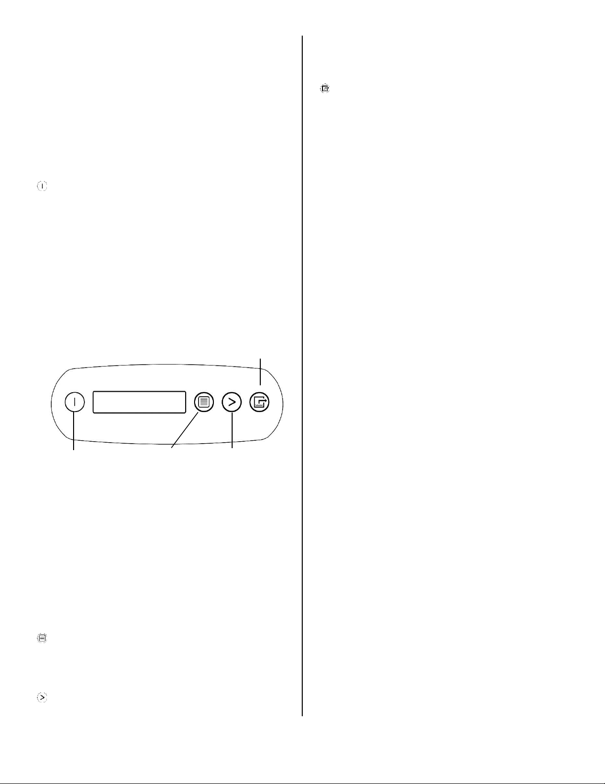
1. Do not turn unit off or move it until it has returned
to normal operating mode. To confirm unit status,
review the control panel. The control panel will dis-
play one of the following messages:
Defrost in progress:
UNIT ON 00 HRS
DEFROST XX
Display mode when unit is in defrost mode. XX indicates
the seconds remaining on the defrost cycle.
Shutdown sequence
WAIT FOR
DEFROST XX
Display mode when unit in defrost and unit is powered
down (shut off by user). Unit will complete the defrost cy-
cle to remove any built-up ice then purge the pump. XX
indicates the seconds remaining on the defrost cycle.
Drying sequence
WAIT FOR
UNIT DRYING XX
Display mode when unit not in defrost and unit is pow-
ered down (shut off by user). Unit will complete the 5 mi-
nute drying cycle then purge the pump. XX indicates the
seconds remaining on the drying cycle.
Normal display:
UNIT ON 00 HRS
INLET XX° C
The unit has completed a defrost and drying cycle and
has returned to normal mode. You may now procede to
step 2.
2. Gently rock the machine to ensure any water re-
maining on interior surfaces falls into the sump area.
3. Press the PURGE key. When the purge cycle is
complete, turn the unit off.
4. Remove the external drain hose, drain it carefully,
coil it, and secure it with one of the straps provided.
5. Remove the power cord, coil it neatly, and secure
it with one of the straps provided.
TRANSPORTATION AND STORAGE
NOTICE: Always remove power cord before moving,
transporting, or storing the unit.
NOTICE: Handle the unit carefully. Do not drop, throw,
or place the unit where it could fall. Rough treatment can
damage this equipment and may create a hazardous
condition or void warranty.
Do not expose the control panel to moisture, snow
or rain.
Protect from freezing.
Store and transport securely to avoid any damaging
impact to internal parts.
Secure during transport to prevent sliding and possi-
ble injury to vehicle occupants.
MAINTENANCE SCHEDULE
WARNING! ELECTRIC SHOCK HAZARD. Unplug unit
before cleaning or servicing.
WARNING: Risk of dust and contaminants exposure.
Use of respirator mask and gloves is recommended. If
unit has been exposed to potentially dangerous contami-
nants, clean thoroughly and sanitize before reuse.
NOTICE: The unit is fitted with sensitive electronic sen-
sors. Protect the sensors and their lead wires from dam-
age and do not expose them to water or cleaning solu-
tion.
The following tools and supplies are needed to com-
plete the maintenance procedures described in this
manual:
Philips screwdriver
10 mm wrench
6 mm hex bit
¼in. nut driver
Cleaning cloths
HEPA vacuum cleaner with soft brush nozzle and
crevice nozzle.
Recommended
Cordless drill, small knife, small-jaw pliers, coil clean-
ing solution, rotomolded housing cleaning solution.
Before each use
Inspect the electrical cord for damage. Look for fray-
ing, cuts, etc. Replace the cord if you find any damage.
Inspect filter. Replace if accumulation of dust and de-
bris is visible.
NOTICE: Replace used filters only with a new Dri-Eaz 4-
PRO filter part no. F583 (24-pack). Other filter types do
not provide adequate filtration or airflow. Each filter is in-
dividually wrapped to protect filtration effectiveness. Re-
move the wrapper before installing the filter into the de-
humidifier.

07-01839G F413 6 Dri-Eaz Products, Inc.
Monthly
Inspect coils. Clean when dust accumulation is visible.
In normal use, dust can accumulate and can restrict air-
flow, reducing performance and causing the unit to over-
heat. Use a vacuum cleaner with a brush tool and a soft
cloth to remove any debris. Take care not to damage
any interior components.
To maintain appearance, wipe interior and exterior sur-
faces with a damp cloth. For deep cleaning and a last-
ing, protective shine, use an automotive interior cleaner.
As Needed
Clean pump check valve and basin. If the unit displays
the message “ER9 PUMP BLOCKED PUMP & HOSE”,
the pump check valve and pump basin may need to be
cleaned. Remove grills and cover as shown in Fig. B.
Remove screws from pump base and lift out pump. Wipe
out pump basin with a damp cloth. Inspect the pump
base for build-up of debris and clean if needed. Un-
thread barbed fitting with check valve and rinse fitting
and check valve with clean water. Reinstall check valve
into barbed fitting and install the barbed fitting into pump.
Do not overtighten. Reinstall pump on base. Reinstall
cover and grills.
Clean coils. With the cover removed, inspect both coils.
If excessive dust and debris is present, vacuum thor-
oughly and/or clean with coil cleaner.
Remove the 4 screws
from housing and 2
top screws each from
inlet and outlet grills
and lift off cover.
Fig. B: Disassembly for Cleaning

07-01839G F413 7 Dri-Eaz Products, Inc.
SYSTEM MESSAGES
The Control Panel will display the following messages based on system performance and environmental conditions. User
action, if any is required, is indicated in the third column.
CONTROL PANEL
MESSAGE
EXPLANATION
USER ACTION
INITIALIZING
Unit is powering up.
None
FIRMWARE VERSION
XXX
Indicates control board firmware version number.
None
F583-XXX
Model number.
None
OFF
Unit has finished powering up and is operating.
None
PLEASE WAIT
COMP. DELAY XX
60s delay before compressor turns on. Allows system
pressure to equalize.
None
UNIT ON XXXX HRS
INLET XXX°F / XX%
First line: indicates total operating hours.
Second line: Toggles between inlet temperature and in-
let RH every 2 seconds.
None
HUMIDISTAT
INLET XXX°F / XX%
First line: indicates unit is in humidistat mode
Second line: Toggles between inlet temperature and in-
let RH every 2 seconds.
None
LOW TEMP
INLET XXX°F/ XX%
F515 only. Unit shuts off if inlet temp below 45°F/7°C. Turns
back on when inlet reaches 50°F/10°C.
None
---
PUMP PURGING XX
Pump is purging with countdown in seconds. Press key
again to stop if needed.
None
HI TEMP CYCLE
REMAINING XX MIN
Unit overload limit reached. Cool-down initiated.
None
---
DEFROST XX
Unit is defrosting, with countdown in seconds.
None
WAIT FOR
DEFROST XXX
Unit turned off when coil is cold or already in a defrost
cycle. Proceeds to finish cycle or initiate one to clear the
coils of ice before storage.
None
WAIT FOR
UNIT DRYING XXX
Occurs when unit is turned off and coil is not frozen.
Clears the coils of water before storage.
None
CHECK FILTER >
---
Prompt to check filter.
Change if necessary. Press
the > key to reset
CLEAN COILS >
---
Prompt to clean coils and interior.
Clean coils. Press the > key
to reset

07-01839G F413 8 Dri-Eaz Products, Inc.
ERROR MESSAGES
If the control system detects an error, it will produce an error (“ER”) message. If this occurs, first unplug the unit and then
plug it back in. This will usually reset the electronics, and the unit will begin operating normally. If the error message reap-
pears, refer to the explanations and solutions shown below. If these solutions do not fix the problem, contact your local
authorized service center.
CONTROL PANEL
MESSAGE
EXPLANATION AND SOLUTION
ER4 DEFROST
SENSOR CONNECT
or
ER4 OUTLET
SENSOR CONNECT
Temp sensor is open, missing, or shorted. Check that temp sensors are installed cor-
rectly on control panel. If error persists, contact service.
ER5 SENSOR
CONNECTION ON BD
Inlet Temp/RH sensor is open, missing, or shorted. Check that inlet temp/RH sensor is
installed correctly on control panel and inlet shroud. If error persists, contact service.
ER6 CONTACT
SERVICE CENTER
Current sensor failure. If error persists, contact service.
ER7 INVALID
MODEL SETTING
Incorrect or unsupported DIP switch settings. Contact Dri-Eaz service department for
correct DIP switch settings.
ER8 BUTTON STUCK
ALL BUTTONS
Key is stuck or has been held down too long. Contact service.
ER9 PUMP BLOCKED
PUMP & HOSE
Check for obstructions in drain hose. Check the pump.

07-01839G F413 9 Dri-Eaz Products, Inc.
TROUBLESHOOTING
FAULT
CAUSE
SOLUTION
Water drips out
when moving unit
Unit was unplugged before
purging was complete.
Purge unit before moving. See “At the End of the Job,” p. 5.
Unit does not op-
erate
Unit not switched on.
No power to machine.
Switch unit on.
Plug in unit; check power cord connection at wall outlet and at
base of unit.
Unit operating,
but room not dry
Not enough time to dry.
Poor air movement in room.
Excessive moist air infiltration.
Make sure “Humidistat” is OFF.
Allow more time for drying.
Increase air movement with air movers.
Seal off area to reduce infiltration.
Unit collects too
little water
Room air is dry.
Room temperature is too low.
Filter is clogged.
Coils are clogged.
Make sure “Humidistat” is OFF.
Confirm humidity level with hygrometer.
Increase room temperature.
Check filter. Replace as necessary.
Check coils. Clean as necessary.
If the problem you are experiencing is not listed here, call your local distributor or contact
our Service Department toll-free at 800-932-3030 for further assistance.
SPECIFICATIONS
Name
Revolution LGR Dehumidifier
Model F413
Dimensions (W ×H ×D)
12.5 ×17.6 ×21.5 in.
31.8 ×44.7 ×54.6 cm
Weight (w/ cord & hose)
65 lbs. | 29.5 kg
Amps
6.2 amps at 80°F/60% RH
Power
115V / 60Hz
Air movement
121–180 CFM | 3.43–5.1 CMM
Water removal
80 pts/day | 38 L/day
at 80°F/60% RH (AHAM)
134 pts/day | 63 L/day
at 90°F/90% RH
Operating temperature range
33–100°F |1–38°C
Safety
ETL listed to CSA standards
Specifications are subject to change without notice. Some values
may be approximate.
WARNING: This product may expose you to
chemicals, including lead and phthalates, known
to the State of California to cause cancer, birth defects,
or other reproductive harm. For more information, go to
P65Warnings.ca.gov
PARTS INCLUDED
40 ft. (12 m) of drain hose with quick-connect fitting.
25 ft. (7.6 m) detachable power cord.
4-PRO Air filter reorder no. F583 (24 pk)
OPTIONAL
Duct Attachment Kit (F530)
ADDITIONAL PRODUCT INFORMATION and current
documentation is available at http://Revo.Legend-
BrandsRestoration.com.
FOR PARTS AND SERVICE CALL YOUR LOCAL DIS-
TRIBUTOR or Dri-Eaz at 800-932-3030. Legend-
BrandsRestoration.com
Visit warranty.LegendBrandsRestoration.com and regis-
ter your purchase to ensure you receive any important
product releases.

07-01839G F413 10 Dri-Eaz Products, Inc.
Manual de instrucciones
Deshumidificador Revolution LGR
Modelo F413
DRI-EAZ PRODUCTS, INC
15180 Josh Wilson Road, Burlington, WA 98233
Teléfono: 800-932-3030 Fax: 360-757-7950 http://Revo.LegendBrandsRestoration.com
El deshumidificador Dri-Eaz®Revolution LGR reduce la humedad en ambientes cerrados al eliminar el
vapor de agua del aire. El Revolution es ideal para la restauración de daños ocasionados por el agua, el
secado estructural, la construcción y muchas otras aplicaciones que requieren deshumidificación tempo-
ral de alto rendimiento.
Patentes: http://www.LBpatents.com
LEA Y GUARDE ESTAS INSTRUCCIONES
Lea y entienda el manual antes de operar el deshu-
midificador.
ADVERTENCIA! Peligro de sufrir una descarga eléc-
trica, lastimarse con el ventilador rotatorio y que-
marse con una superficie caliente. Desenchufe la
unidad antes de abrir la tapa para limpiarla o hacerle
mantenimiento. La unidad debe tener descarga a tie-
rra.
Controle el cable de alimentación antes de usarlo.
Si está dañado, no lo use. Para desenchufar la uni-
dad, tire siempre del enchufe (nunca del cable).
Coloque el enchufe de tres clavijas que está en el
extremo del cable de alimentación en un tomaco-
rriente con descarga a tierra adecuado. No use
adaptadores. Nunca corte la tercera clavija. No use
cables prolongadores.
La unidad debe utilizarse en un circuito eléctrico de
115 V/60 Hz, protegido por un interruptor del circuito
de fallos de conexión a tierra (GFCI, por sus siglas
en inglés).
No utilice el aparato en agua estancada. Mantenga
el motor y los cables secos.
¡ADVERTENCIA! Desconecte la unidad antes de
limpiarla o darle mantenimiento.
Apague la unidad y desconéctela antes de levan-
tarla o moverla.
Maneje la unidad con cuidado. Opere siempre la
unidad sobre una superficie estable y nivelada. No
la deje caer, no la tire ni la coloque donde pueda
caerse. Un trato brusco puede dañar la unidad y
puede generar una condición peligrosa o anular la
garantía.
Inspeccione el cable de alimentación antes de utili-
zar la unidad. Si el cable está dañado, no utilice la
unidad. Sujete siempre la clavija (no el cable) para
desconectarla.
La unidad debe operarse en un circuito de 115V/60
Hz protegido por un dispositivo interruptor de cir-
cuito por falla en tierra (GFCI, por sus siglas en in-
glés).
ADVERTENCIA
ADECUADO RETIRO DEL ENCHUFE
Tome el enchufe IEC y tire recto
IMPORTANTE: Cualquier daño en el re-
ceptáculo IEC o en el deshumidificador con-
secuencia de un inadecuado retiro del cable
eléctrico no será cubierto por la garantía. El
cable eléctrico IEC es un elemento con
desgaste y no está cubierto por la garantía.

07-01839G F413 11 Dri-Eaz Products, Inc.
No intente reparar la unidad. Para consultar una
lista de los Centros de Servicio Autorizados, llame al
Servicio de Dri-Eaz al 800-932-3030.
ANTES DE COMENZAR
Registro de la garantía
Visite warranty.LegendBrandsRestoration.com para re-
gistrar su compra. El registro nos permite ayudarle mejor
con el uso, mantenimiento o servicio de su equipo, y co-
municarnos con usted en caso de debamos proporcio-
narle información de seguridad importante acerca de su
producto Dri-Eaz. Si usted considera que la unidad ne-
cesita recibir servicio, tenga a la mano la información so-
bre el modelo de su equipo, el número de serie y el
comprobante de compra original, y llame a su distribui-
dor para que le ayude a obtener una autorización de de-
volución de materiales (RMA, por sus siglas en inglés).
INTRODUCCIÓN
El deshumidificador Revolution reduce la humedad en
entornos cerrados estructurales al eliminar el vapor de
agua del aire. Con el uso apropiado, el Revolution
puede ayudar a secar materiales estructurales, aisla-
miento y contenido húmedos, así como a mantener un
nivel saludable de humedad. El uso del Revolution tam-
bién puede evitar daños secundarios causados por el
exceso de humedad.
Cómo funciona el Revolution
El deshumidificador por refrigeración Revolution utiliza
un ventilador para extraer el aire húmedo y condensarlo
en agua, la cual se acumula en una bandeja y se bom-
bea de forma automática hacia afuera a través de una
manguera de desagüe. La unidad se puede configurar
para que funcione de manera continua o el usuario
puede seleccionar el modo de humidistato. En el modo
de humidistato, el Revolution se enciende y se apaga
automáticamente para mantener el nivel de humedad de
entrada que el usuario haya seleccionado.
CONTROLES E INSTRUCCIONES DE
OPERACIÓN
Coloque la unidad en posición vertical
AVISO: Siempre almacene, transporte y utilice la
unidad en posición horizontal. Si la unidad llegara a
colocarse en posición vertical, póngala en posición
horizontal de nuevo y déjela reposar durante al me-
nos 30 minutos antes de encenderla.
Ubicación del deshumidificador
Para obtener los mejores resultados, utilice los deshumi-
dificadores en un área cerrada. Cierre todas las puertas
y ventanas que den al exterior para maximizar la eficien-
cia de la remoción de agua. Coloque el deshumidificador
lejos de obstrucciones y manténgalo alejado de cual-
quier objeto que pueda bloquear el flujo de aire dentro y
fuera de la unidad. Para obtener más información
acerca de cómo crear un ambiente de secado óptimo,
comuníquese con Dri-Eaz al 8009323030.
Configuración de la manguera de desa-
güe
La bomba de condensado del Revolution se conecta a
una manguera de desagüe de plástico. Esta manguera
está equipada con una conexión de acoplamiento rápido
para conectarla rápidamente a la manguera de desagüe
de 40 pies (12 m) provista. Desenrolle toda la manguera
y coloque el extremo suelto en un lavabo, desagüe,
cubo o al aire libre (en cualquier lugar donde el agua
pueda drenarse de forma segura).
AVISO: Desenrolle y enderece toda la manguera de
desagüe. No deje ninguna parte de la manguera enro-
llada ni coloque el extremo de la manguera a 20 pies (6
m) por encima de la parte inferior de la unidad. También
vea si hay torceduras u otras obstrucciones que podrían
restringir el flujo de agua. Las obstrucciones pueden
provocar una retención del agua y ocasionar derrames.
Conecte el cable eléctrico
El Revolution debe conectarse a un tomacorriente de
115 voltios con protección de GFCI especificado por lo
menos para 15amperios. Siempre conecte firmemente el
cable en la unidad primero y luego conecte el otro ex-
tremo a un tomacorriente adecuado.
Asas para
transporte
Imagen A: Identificación de las piezas
Conexión rá-
pida del
desagüe de
condensa-
ción
Entrada de
aire
Panel de
control
Retire o in-
serte el filtro
de aire aquí.
Salida de
aire
Tomaco-
rriente
Soportes de
almacenaje
del cordón
eléctrico y la
manguera.
Sensor de
tempera-
tura y hu-

07-01839G F413 12 Dri-Eaz Products, Inc.
Pantalla de inicio y modos de visualización norma-
les
Cuando la unidad se conecta por primera vez en la ali-
mentación de corriente alterna (CA), la pantalla del pa-
nel de control mostrará brevemente una serie de lectu-
ras en ciclo. Esto es parte del procedimiento de auto-
diagnóstico de la unidad y no se requiere ninguna inter-
vención del usuario.
Encienda la unidad
El panel de control del deshumidificador Revolution tiene
una pantalla y un panel táctil con cuatro botones. Pre-
sione el botón ON/OFF (ENCENDIDO / APAGADO)
para encender la unidad. La unidad realizará un conteo
regresivo de retardo del compresor (de hasta sesenta
segundos de duración) y un proceso de autodiagnóstico.
Una vez que la cuenta regresiva del compresor y el au-
todiagnóstico se hayan completado, la pantalla cambiará
al modo de visualización normal.
UNIT ON 00 HRS (UNIDAD ENCEN-
DIDA 00 HRS)
INLET 00°C / INLET 00% (ENTRADA
00° C / ENTRADA 00%)
La primera línea de la pantalla muestra el número total
de horas que la unidad ha estado en operación. Este va-
lor puede restablecerse a cero para dar seguimiento a
las horas de trabajo (vea “Restablecimiento de horas de
trabajo” a continuación). La segunda línea de la panta-
lla muestra alternadamente la temperatura de entrada y
la humedad de entrada.
Menú de configuraciones del usuario
El usuario puede cambiar algunas configuraciones de la
pantalla. También se puede mostrar la información del
sistema. Se puede tener acceso a estos elementos pre-
sionando DISPLAY MENU (MENÚ DE PANTALLA). Con
cada pulsación del botón se mostrará el siguiente pará-
metro. Cuando llegue al parámetro que quiera ajustar,
presione MENU SELECTION (SELECCIÓN DE ME-
NÚS) para aumentar el valor. Presione DISPLAY MENU
(MENÚ DE PANTALLA) de nuevo para aceptar la confi-
guración y volver a iniciar el ciclo de visualización.
Tenga en cuenta que sólo se pueden ajustar los ele-
mentos del menú seguidos del símbolo mayor que ( > ).
Todos los ajustes y modos se describen con detalle en
la Guía del panel de control, que se encuentra más ade-
lante.
Mensajes de error
Si el diagnóstico incorporado al Revolution detecta un
problema, la unidad mostrará un mensaje de error. Con-
sulte “Mensajes del sistema” para ver una explicación de
cada mensaje.
Guía del panel de control
ON/OFF (ENCENDIDO / APAGADO). Presione el
botón ON/OFF para encender o apagar la unidad.
Cuando el equipo está encendido, la pantalla indica nor-
malmente PLEASE WAIT COMP. DELAY (ESPERE EL
RETARDO DEL COMPRESOR) y realiza una cuenta re-
gresiva desde un máximo de 60 segundos hasta 0. Este
retardo da tiempo para que se iguale la presión del refri-
gerante con el fin de facilitar el arranque. Una vez que
haya transcurrido el retardo del compresor, la pantalla
mostrará UNIT ON XX HRS (UNIDAD ENCENDIDA XX
HORAS) y alternará entre INLET XX°F (ENTRADA XX°
F e INLET XX% (ENTRADA XX%).
DISPLAY MENU (MENÚ DE PANTALLA). Presione
para alternar entre la visualización de las condiciones
adicionales del deshumidificador y la configuración del
usuario. Para volver al menú principal, presione el botón
ON/OFF (ENCENDIDO / APAGADO) una sola vez.
MENU SELECTION (SELECCIÓN DE MENÚS). Pre-
sione para cambiar los valores de los ajustes "User Defi-
ned" (definidos por el usuario). El botón de MENU SE-
LECTION (SELECCIÓN DE MENÚS) funciona como te-
cla de flecha hacia arriba para ajustar el punto de opera-
ción del funcionamiento en el modo de humidistato.
Consulte la sección Menú de configuración del usuario
(más adelante) para ver más detalles.
PURGE (PURGA). Presione para vaciar el agua del
depósito de la bomba de condensado. En la pantalla
aparecerá PURGING PUMP (PURGANDO BOMBA) con
un número de cuenta regresiva. NOTA: Durante el fun-
cionamiento normal, la bomba se purga automática-
mente.
ON/OFF (ENCENDIDO /
APAGADO)
Presione y suelte para encender
o apagar la unidad.
DISPLAY MENU (MENÚ
DE PANTALLA)
Presione para seleccionar el si-
guiente elemento del menú. El ele-
mento del menú se mostrará en la
pantalla.
MENU SELECTION /
UP KEY (SELECCIÓN DE
MENÚS / FLECHA HA-
CIA ARRIBA)
Presione para cambiar o seleccio-
nar los valores en el menú desple-
gado.
BOMBA DE PURGADO
Presione y suelte para empezar a
purgar. La pantalla mostrará una
cuenta regresiva de los segundos
que falten para que se complete la
purga.
PANEL DE CONTROL
ON/OFF
ON/OFF
PANTALLA DISPLAY
DISPLAY
MENU
DISPLAY
MENU
MENU SELECTION /
UP KEY
PURGE

07-01839G F413 13 Dri-Eaz Products, Inc.
AJUSTES DE USUARIO
Solo se pueden ajustar los elementos del menú que estén seguidos de un símbolo de «mayor que» (>). Si no se selecciona ninguna tecla en las si-
guientes pantallas en un lapso de 5 minutos: INLET OUTLET (ENTRADA SALIDA), DPR GRAIN (GRANO DE DPR) (INLET OUTLET para los modelos
230V), la pantalla volverá al modo de visualización normal. En todos los demás elementos de menú, la pantalla regresará al modo de visualización
normal después de 20 segundos. Los elementos que no tienen el símbolo (>) son únicamente para información y no se pueden cambiar ni restablecer.
Presione DISPLAY
MENU (MOSTRAR
MENÚ) para pasar a la
siguiente opción del
menú. ↓
Presione MENU SELECTION (SELECCIÓN DEL MENÚ) para cambiar el ajuste. →
1. HRS REINICIAR>
FALLA DE LUZ X
1. H DE TRABAJO 0
FALLA DE LUZ 0
Presione para restablecer a 0.
2. ENTRADA SALIDA
100’80% 115’30%
Sólo para información.
3. ENTRADA-SALIDA
XX.X g/kg
4. FILTRO CAMBIAR
XXX HR >
5. FILTRO CAMBIAR
0 HRS
Presione para borrar las horas de limpieza del filtro.
5. LIMPIAR BOBINA
XXX HRS >
5. LIMPIAR BOBINA
0 HRS
Presione para borrar las horas de limpieza de la bobina.
6. HIGROSTATO
MODO APAGADO>
6. HIGROSTATO
MODO PRENDIDO>
Presione para poner en ON u OFF (ENCENDER o APAGAR).
7. CONSIGNA
HIGROSTATO XX%>
Presione para alternar entre el 40% y el 90% en incrementos de 5% (el valor predeterminado es de 50%).
8. IDIOMA
ESPANOL >
8. SPRACHE
DEUTSCH >
8. LANGUE
FRANCAIS >
8. LANGUAGE
ENGLISH >
Presione para cambiar
las opciones de idioma.
9. TEMPERATURA
’C >
9. TEMPERATURA
’F >
Presione para cambiar a °F o °C.
10. TEMP BOBINA
XX’
Sólo para información.
11. CORR COMPRS
XX.X A
Sólo para información.
12. FIRMWARE
3.0X F583-XXX
Sólo para información.
13. TOTAL DE HRS
XXXX HR
(Regresa al
elemento del menú
superior).
La siguiente sección está disponible sólo en las unidades equipadas con sistema inalámbrico.
14. SENSOR ID
XXXXXXXX
(Regresa al
elemento del menú
superior).

07-01839G F413 14 Dri-Eaz Products, Inc.
AL FINAL DE LA OPERACIÓN
Para reducir la posibilidad de goteos al mover la uni-
dad, siga estos pasos adicionales para asegurarse
de que toda el agua sea retirada de la unidad.
AVISO: Para asegurar que toda el agua sea quitada del
deshumidificador, la unidad habrá de completar el ciclo
de descongelamiento incluso si se halla apagada. Si la
unidad fuera desenchufada durante el ciclo de descon-
gelamiento, es posible que se acumule en la misma el
exceso de agua y gotear cuando se la traslade.
AVISO: Para asegurarse de que el tanque de conden-
sado se vacíe por completo mientras se hace el
purgado, asegúrese de que la unidad esté en posición
vertical sobre una superficie horizontal.
1. Si la unidad está en un ciclo de desconge-
lamiento, espere hasta que regrese al modo normal
de funcionamiento antes de proceder. Para compro-
bar, revise el panel de control. Éste mostrará uno de
los siguientes mensajes:
Descongelamiento en progreso:
PRENDIDO XXXX H
DESCONGELE XX
Modo de visualización cuando la unidad está en modo
de descongelamiento. XX indica los segundos restantes
en el ciclo de descongelamiento.
Secuencia de apagado
ESPERE A QUE SE
DESCONGELE XX
Modo de visualización cuando la unidad está en modo
de descongelamiento es apagada (por el usuario). La
unidad completará el ciclo de descongelamiento para
quitar cualquier hielo acumulado y luego purgará la
bomba. XX indica los segundos restantes en el ciclo de
descongelamiento.
Secuencia de secado
ESPERA PARA
SECADO DE LA UNIDAD XX
Modo de visualización cuando la unidad no está en
modo de descongelamiento y es apagada (por el
usuario). La unidad completará el ciclo de secado de
5 minutos y después purgará la bomba. XX indica los
segundos restantes en el ciclo de descongelamiento.
Visualización normal:
UNIDAD EN 00 h
ENTRADA XX °C / ENTRADA XX%
Espere hasta que el control muestre la pantalla normal
antes de proceder.
2. Mueva suavemente la máquina para asegurarse
de que cualquier resto de agua en las superficies
interiores caiga en el área del colector.
3. Pulse la tecla de PURGADO . Cuando se
complete el ciclo de purgado, apague la unidad.
4. Retire la manguera de drenaje externo, escúrrala
con cuidado, enróllela y sujétela con una de las tiras
al costado de la unidad.
TRANSPORTE Y ALMACENAMIENTO
AVISO: Maneje la unidad con cuidado. No la deje caer,
no la tire ni la coloque donde pueda caerse. Un trato
brusco puede dañar el equipo y puede generar una con-
dición peligrosa o anular la garantía.
No exponga el panel de control a la humedad, la
nieve ni la lluvia.
Proteja la unidad contra la congelación.
Almacene y transporte la unidad de forma segura
para evitar que las piezas internas se dañen.
Asegúrela durante el transporte para evitar desliza-
mientos y posibles lesiones a los ocupantes del
vehículo.
PROGRAMA DE MANTENIMIENTO
¡ADVERTENCIA! PELIGRO DE DESCARGA ELÉC-
TRICA. Desconecte la unidad antes de limpiarla o
darle mantenimiento.
ADVERTENCIA: Riesgo de exposición al polvo y a con-
taminantes. Se recomienda utilizar una máscara con
respirador y guantes. Si la unidad ha estado expuesta a
contaminantes potencialmente peligrosos, limpie y de-
sinfecte la unidad a fondo antes de volver a utilizarla.
AVISO: La unidad está equipada con sensores electró-
nicos sensibles. Proteja los sensores y las puntas de
sus cables contra daños y no los exponga al agua ni a la
solución de limpieza.
Se requieren las siguientes herramientas y materia-
les para llevar a cabo los procedimientos de mante-
nimiento que se describen en este manual:
Destornillador philips
Llave de 10 mm
Punta hexagonal de 6 mm
Llave de tuercas de ¼pulg.
Paños para limpieza
Retire los 4 tornillos
de la carcasa y los 2
tornillos superiores de
cada una de las parri-
llas de entrada y sa-
lida, y levante la cu-
bierta.
Imagen B: Desmontaje para limpieza

07-01839G F413 15 Dri-Eaz Products, Inc.
Aspiradora de absorción de partículas de alta eficien-
cia (HEPA, por sus siglas en inglés) con boquilla de
cepillo suave y boquilla estrecha.
Herramientas y materiales recomendados
Taladro inalámbrico, cuchilla pequeña, pinzas de qui-
jada pequeña, solución de limpieza para la bobina,
solución de limpieza de carcasa rotomoldeada.
Antes de cada utilización
Revise si el cable eléctrico está dañado. Busque que-
maduras, cortaduras, etc. Reemplace el cable si está
dañado.
Inspeccione el filtro: reemplácelo si observa que hay
acumulación de polvo y suciedad.
AVISO: Reemplace los filtros usados con un filtro nuevo
Dri-Eaz, número de pieza F583 (paquete de 24). Otros
tipos de filtros no proporcionan filtración o flujo de aire
adecuados. Cada filtro se envuelve individualmente para
conservar la eficiencia de la filtración. Quite la envoltura
antes de instalar el filtro en el deshumidificador.
Cada mes
Inspeccione las bobinas. Limpie cuando la acumula-
ción de polvo sea visible. Con el uso normal, el polvo
puede acumularse y puede restringir el flujo del aire, lo
cual reduce el rendimiento y ocasiona que la unidad se
sobrecaliente. Utilice una aspiradora con un cepillo y un
paño suave para eliminar cualquier residuo. Tenga cui-
dado de no dañar los componentes internos.
Para mantener una buena apariencia, limpie las su-
perficies interiores y exteriores con un paño húmedo.
Para una limpieza profunda y un brillo duradero y pro-
tector, utilice un limpiador para interiores de automóvi-
les.
Según se requiera
Limpie la válvula de retención y el depósito de la
bomba. Si la unidad muestra el mensaje “ER9 PUMP
CHECK PUMP & HOSE” (ERROR 9: BOMBA BLO-
QUEADA; REVISAR LA BOMBA Y LA MANGUERA), es
posible que sea necesario limpiar la válvula de retención
y el recipiente de la bomba. Quite las parrillas y la cu-
bierta según se muestra en la Imagen B. Quite los torni-
llos de la base de la bomba y sáquela. Limpie el depó-
sito de la bomba con un paño húmedo. Revise si hay es-
combros acumulados en la base de la bomba y límpiela
en caso de ser necesario. Desenrosque la boquilla es-
triada de la válvula de retención y enjuague la boquilla y
la válvula de retención con agua limpia. Vuelva a instalar
la válvula de retención en la boquilla estriada e instale la
boquilla en la bomba. No apriete demasiado. Vuelva a
instalar la bomba en la base. Vuelva a instalar la cu-
bierta y las parrillas.
Limpie las bobinas. Con la cubierta retirada, inspec-
cione las dos bobinas. Si hay polvo y suciedad, limpie a
fondo con una aspiradora o limpie con limpiador para
bobinas.

07-01839G F413 16 Dri-Eaz Products, Inc.
MENSAJES DEL SISTEMA
El panel de control mostrará los siguientes mensajes con base en el desempeño del sistema y las condiciones ambienta-
les. En caso de que se requieran, se indican las acciones del usuario en la tercera columna.
CONTROL PANEL MESSAGE
EXPLANATION
USER ACTION
INICIALIZAR
La unidad está encendiendo.
Ninguna
VERSION FIRMWARE
XXX
Indica el número de versión del firmware del tablero de
control.
Ninguna
F583-XXX
Número de modelo.
Ninguna
APAGADO
La unidad ha terminado de encender y está funcio-
nando.
Ninguna
POR FAVOR ESPERE
RETAR COMPRS XX
60s de espera antes de que encienda el compresor.
Permite que se iguale la presión del sistema.
Ninguna
PRENDIDO XXXX HR
ENTRADA XXX°C/ XX%
Primera línea: indica el total de horas de operación.
Segunda línea: Alterna cada 2 segundos entre la tem-
peratura de entrada y la humedad relativa de entrada.
Ninguna
HIGROSTATO
ENTRADA XXX°C/ XX%
Primera línea: indica que la unidad está en modo de hi-
grostato
Segunda línea: Alterna cada 2 segundos entre la tem-
peratura de entrada y la humedad relativa de entrada.
Ninguna
BAJA TEMP
ENTRADA XXX°C/ XX%
F515 únicamente. La unidad se apaga si la temperatura
de entrada está por debajo de los 45 °F. Se vuelve a
encender cuando la entrada alcanza los 50 °F.
Ninguna
---
PURGA DE AGUA XX
La bomba se está purgando con cuenta regresiva en
segundos. Presione la tecla de nuevo para parar en
caso de que sea necesario.
Ninguna
CICLO ALTA TEMP.
MIN RESTANTES XX
Se llegó al límite de sobrecarga de la unidad. Se inició
el enfriamiento.
Ninguna
---
DESCONGELE XX
La unidad se está descongelando con cuenta regresiva
en segundos.
Ninguna
ESPERE A QUE SE
DESCONGELE XXX
La unidad se apaga cuando la bobina está fría o si ya
está en un ciclo de descongelación. Procede a terminar
el ciclo o a iniciar uno que libere las bobinas de hielo
antes de su almacenamiento.
Ninguna
ESPERE A QUE SE
SECADO XXX
Ocurre cuando la unidad se apaga y la bobina no está
congelada. Saca el agua de las bobinas antes de su al-
macenamiento.
Ninguna
LIMPIAR FILTRO >
APAGADO
Indicación para cambiar el filtro.
Cambie el filtro. Presione la
tecla > para reiniciar
LIMPIAR BOBINA >
---
Indica limpiar las bobinas y el interior.
Limpiar las bobinas. Presio-
nar la tecla > para restablecer

07-01839G F413 17 Dri-Eaz Products, Inc.
MENSAJES DE ERROR
Si el sistema de control detecta un error, se producirá un mensaje de error ("ER"). Si esto ocurre, desconecte la unidad y
luego conéctela de nuevo. Por lo general, esto restablecerá la parte electrónica, y la unidad comenzará a funcionar nor-
malmente. Si el mensaje de error vuelve a aparecer, consulte las explicaciones y soluciones que se muestran a continua-
ción. Si estas soluciones no se resuelven el problema, póngase en contacto con su centro de servicio local autorizado.
MENSAJE DEL PANEL DE
CONTROL
EXPLICACIÓN Y SOLUCIÓN
ER4 CONEXION SEN-
SOR DESCONG
or
ER4 CONEXION
SENSOR SALIDA
Sensor de temperatura abierto, faltante, o en cortocircuito. Compruebe que los senso-
res de temperatura estén instalados correctamente en el panel de control. Si el error
persiste, comuníquese al centro de servicio.
ER5 CONEXION
SENSOR TABLERO
Sensor de temperatura/humedad relativa de entrada abierto, faltante, o en cortocircuito.
Compruebe que el sensor de temperatura/humedad relativa esté instalado correcta-
mente en el panel de control y la cubierta de entrada. Si el error persiste, comuníquese
al centro de servicio.
ER6 CONTACTAR CEN-
TRO DE SERV
Falla en el sensor de corriente. Si el error persiste, comuníquese al centro de servicio.
ER7 INVAL
AJUSTE
Configuración incorrecta o incompatible de los interruptores DIP. Comuníquese al cen-
tro de servicio de Dri-Eaz para obtener la configuración correcta de los interruptores
DIP.
ER8 BOTON
ATORADO
La tecla se ha atascado o se ha oprimido por demasiado tiempo. Comuníquese al cen-
tro de servicio.
ER9 BOMBA TAPADA
BOMBA&MANGUERA
Compruebe si hay obstrucciones en la manguera de desagüe. Revise la bomba.

07-01839G F413 18 Dri-Eaz Products, Inc.
SOLUCIÓN DE PROBLEMAS
FALLA
CAUSA
SOLUCIÓN
Gotea agua
cuando se mueve
la unidad
Se desconectó la unidad antes
de terminar de purgar.
Purgue la unidad antes de moverla. Vea “Al final del trabajo”
en la pág. 14.
La unidad no fun-
ciona
La unidad no está encendida.
No hay alimentación a la má-
quina.
Encienda la unidad.
Conecte la unidad, revise la conexión del cable de alimenta-
ción en el tomacorriente de la pared y en la base de la unidad.
La unidad fun-
ciona, pero la ha-
bitación no se
seca
El tiempo no es suficiente para
el secado.
Poco movimiento del aire en la
habitación.
Infiltración excesiva de aire
húmedo.
Permita más tiempo para el secado.
Aumente el movimiento del aire con ventiladores.
Selle el área para reducir la infiltración.
La unidad recoge
muy poca agua
El aire de la sala es seco.
La temperatura de la sala es
demasiado baja.
El filtro está lleno.
Las bobinas están obstruidas.
Verifique que “Humidistat” esté apagado.
Confirme el nivel de humedad con un higrómetro.
Aumente la temperatura de la sala.
Examine el filtro. Reemplácelo de ser necesario.
Examine las bobinas. Límpielas de ser necesario.
Si el problema que experimenta no está en esta lista, llame a su distribuidor local a
la línea sin costo de nuestro departamento de servicio al 800-932-3030 para obtener más ayuda.
ESPECIFICACIONES
Nombre
Deshumidificador Revolution LGR
Modelo F413
Dimensiones (ancho x alto x
fondo)
12.5 ×17.6 ×21.5 cm
31.8 ×44.7 ×54.6cm
Peso (c/cable y manguera)
65 libras. | 29.5 kg
Amperios
6.2 amperios a 80° F / 60% de RH
Energía
115V / 60 Hz
Movimiento del aire
121–180 CFM | 3.43–5.1 CMM
Eliminación del agua
80 pts/día | 38 L/día
a 80° F / 60% HR (AHAM)
134 pts/día | 63 L/día
a 90° F / 90% RH
Rango de temperatura de
operación
33–100° F |1–38° C
Sguridad
Certificación de ETL conforme a
las normas CSA
Las especificaciones están sujetas a cambios sin previo aviso. Al-
gunos valores pueden ser aproximados.
PIEZAS INCLUIDAS
Manguera de desagüe de 40 pies (12 m) con conexión
de acoplamiento rápido.
Cable de alimentación extraíble de 25 pies (7.6 m).
Filtro de aire. Reordenar N.° F583 (24 paquetes)
OPTIONAL
Duct Attachment Kit (F530)
Hay INFORMACIÓN ADICIONAL DEL PRODUCTO y
documentos actualizados disponibles en http://Revo.Le-
gendBrandsRestoration.com.
PARA PEDIR INFORMACIÓN SOBRE PIEZAS Y SER-
VICIO, LLAME A SU DISTRIBUIDOR LOCAL o a
DriEaz al 8009323030.www.drieaz.com
Visite el sitio warranty.LegendBrandsRestoration.com y
registre su compra para garantizar que reciba informa-
ción sobre los lanzamientos de productos importantes.
ADVERTENCIA: Este producto puede expo-
nerlo a sustancias químicas entre las que se in-
cluyen plomo y ftalatos, los cuales son considerados en
el estado de California como causantes de cáncer, de-
fectos congénitos u otros daños durante la gestación.
Para obtener más información, visite P65War-
nings.ca.gov

07-01839G F413 19 Dri-Eaz Products, Inc.
Manuel du propriétaire
Déshumidificateur Dri-Eaz®Revolution LGR
Modèle F413
DRI-EAZ PRODUCTS, INC.
15180 Josh Wilson Road, Burlington, WA 98233
Téléphone : 800-932-3030 Fax : 360-757-7950 http://Revo.LegendBrandsRestoration.com
Le déshumidificateur Dri-Eaz®Revolution LGR réduit l’humidité dans des environnements clos en élimi-
nant la vapeur d’eau de l’air. Le déshumidificateur Révolution est idéal pour la restauration des dom-
mages causés par l’eau, le séchage de la structure, la construction, et de nombreuses autres applications
nécessitant une déshumidification temporaire, de haute performance.
Brevets : http://www.LBpatents.com
CONSERVER CES INSTRUCTIONS
INSTRUCTIONS DE SÉCURITÉ IMPORTANTES
AVERTISSEMENT! Ne pas modifier le Unit d’aucune
façon. Utiliser seulement des pièces de rechange
autorisées par Dri-Eaz Products, Inc. Toute modifica-
tion ou l’utilisation de pièces non approuvées peut
constituer un danger et annulera votre garantie.
Contactez votre distributeur autorisé Dri-Eaz pour
obtenir de l’aide.
AVERTISSEMENT! Danger de décharge électrique,
ventilateur tournant et surfaces très chaudes. Dé-
brancher l’appareil avant d’ouvrir le couvercle
pour le nettoyage ou l’entretien. L’appareil doit
être mis à la terre.
Vérifier l’état du cordon d’alimentation avant utili-
sation. Ne pas l’utiliser si le cordon est endom-
magé. Pour débrancher, toujours saisir la prise (et
non le cordon).
Enfoncer les trois fiches de la prise du cordon
dans une prise de courant mise à la terre. Ne pas
utiliser d’adaptateur. Ne jamais sectionner la troi-
sième fiche. Ne pas utiliser de rallonge.
L’appareil doit fonctionner sur un circuit de
115V/60 Hz protégé par un disjoncteur de fuite à
la terre.
Ne pas mettre l’appareil en marche lorsque de
l’eau stagne en surface. Le moteur et le câblage
doivent rester secs.
AVERTISSEMENT! Débrancher l’appareil avant le
nettoyage ou l’entretien.
Éteindre l’appareil et le débrancher avant de le sou-
lever ou de le déplacer.
Manipuler l’appareil avec précaution. Faire toujours
fonctionner l’appareil sur une surface plane et
stable. Ne pas laisser tomber l’appareil et ne pas le
placer où il pourrait tomber. Un mauvais traitement
peut endommager l’appareil et créer une condition
dangereuse ou annuler la garantie.
Inspecter le cordon d’alimentation avant l’utilisation.
Si le cordon est endommagé, ne pas l’utiliser. Tou-
jours saisir la fiche (pas le cordon) pour débrancher.
L’appareil doit être branché sur un circuit 115V/60
Hz protégé par un disjoncteur différentiel de fuite à
la terre (DDFT).
AVERTISSEMENT
COMMENT BIEN ENLEVER LE
CORDON ÉLECTRIQUE
Saisir la prise IEC et tirer en la tenant droite
IMPORTANT : Les dommages occasionnés au récipi-
ent ou au déshumidificateur IEC en raison d’un retrait
incorrect du cordon électrique ne sont pas couverts
par la garantie. Le cordon électrique IEC étant une
pièce d’usure, il n’est pas couvert par la garantie.

07-01839G F413 20 Dri-Eaz Products, Inc.
Ne pas tenter de réparer l’appareil. Pour les centres
de service autorisés, appeler Dri-Eaz service au
800-932-3030.
AVANT DE COMMENCER
Enregistrement de la garantie
Visitez warranty.LegendBrandsRestoration.com pour en-
registrer votre achat. L’enregistrement nous permet de
mieux vous aider à utiliser, entretenir ou réparer votre
appareil et de vous contacter si nécessaire lorsque nous
avons des informations de sécurité importantes con-
cernant votre produit Dri-Eaz. Si vous constatez qu’une
réparation est nécessaire, munissez-vous du modèle de
votre appareil, du numéro de série et de la preuve
d’achat originale avant d’appeler votre distributeur afin
d’obtenir une autorisation de retour de matériel (RMA).
INTRODUCTION
Le déshumidificateur Revolution réduit l’humidité dans
des environnements structurels clos en éliminant la
vapeur d’eau de l’air. Lorsqu’il est utilisé de façon appro-
prié, il peut aider à sécher les matériaux structurels hu-
mides, les matériaux d’isolation, et le contenu, et à
maintenir un niveau d’humidité sain. L’utilisation du Rev-
olution peut également empêcher des dommages sec-
ondaires causés par une humidité élevée.
Comment fonctionne le Revolution
Le réfrigérant déshumidificateur Revolution utilise un
ventilateur pour aspirer l’air humide à l’intérieur et le con-
dense pour le transformer en eau qui s’accumule sur un
plateau et qui est automatiquement pompée à travers
d’un tuyau de vidange. L’appareil peut être configuré
pour fonctionner en continu ou l’utilisateur peut sélec-
tionner le mode Humidistat (Hygrostat). En mode Humid-
istat, le Revolution se met en marche et s’éteint automa-
tiquement pour maintenir le niveau d’humidité d’entrée
sélectionné par l’utilisateur.
COMMANDES ET MODE D’EMPLOI
Placer l’appareil en position horizontale
AVIS : Toujours stocker, transporter et utiliser l’ap-
pareil en position horizontale. Si l’appareil a été
placé en position verticale, le retourner à la position
horizontale et le laisser se reposer pendant au
moins 30 minutes avant de l’allumer.
Positionnement du déshumidificateur
Pour de meilleurs résultats, placer le déshumidificateur
dans un espace clos. Fermer toutes les portes et fenê-
tres qui s’ouvrent vers l’extérieur afin de maximiser l’effi-
cacité de l’élimination de l’eau. Placez votre déshumidifi-
cateur à l’écart de toute obstruction et de tout ce qui
pourrait bloquer la circulation d’air d’entrée et de sortie
de l’appareil. Pour plus d’informations sur la création
d’un environnement de séchage optimal, contacter Dri-
Eaz au 800 932 3030.
Mettre en place le tuyau de vidange
La pompe à condensat du Revolution se connecte à un
tuyau de vidange en matière plastique. Ce tuyau est
équipé d’un raccord rapide pour une connexion rapide
au tuyau de vidange de 40 pieds (12 m) inclus. Déballer
l’ensemble du tuyau et placez l’extrémité libre dans un
évier, un drain, un seau ou à l’extérieur - partout où l’eau
peut s’écouler en toute sécurité. Si vous utilisez un seau
ou un autre récipient pour la collecte de l’eau, le vérifier
régulièrement pour éviter les débordements.
AVIS : Dérouler et redresser le tuyau de vidange. Ne
laisser aucune partie du tuyau enroulée et ne pas placer
l’extrémité du tuyau supérieur à plus de 20 pieds (6
mètres) au-dessus du fond de l’appareil. Vérifier égale-
ment s’il existe des plis ou autres obstacles susceptibles
de limiter le débit d’eau. Les obstructions peuvent
causer des débordements.
Brancher le cordon électrique
Le Revolution doit être branché dans une prise de 115
volts protégée par DDFT évaluée au moins à 15 am-
pères. Toujours brancher le cordon fermement d’abord
dans l’appareil unité, puis brancher l’autre extrémité
dans une prise de courant appropriée.
Écran de démarrage et modes d’affichage normaux
Lorsque l’appareil est branché à une prise secteur, l’af-
fichage du panneau de commande affichera brièvement
une série d’affichages. Cela fait partie de la procédure
d’autodiagnostic de l’appareil et aucune intervention de
l’utilisateur n’est requise.
Poignées de transport
Fig. A : Identification des pièces
Connexion rapide
pour le tuyau de
condensat
Entrée d’air
Panneau de
commande
Retirer/Insérer
le filtre d’air
ici
Sortie d’air
Prise d’ali-
mentation
Pour le
stockage du
cordon et du
tuyau.
Capteur
Temp/HR
Table of contents
Languages:
Other Drieaz Dehumidifier manuals

Drieaz
Drieaz F292-A User manual

Drieaz
Drieaz DrizAir 80 User manual

Drieaz
Drieaz DriTec 4000i User manual

Drieaz
Drieaz F571-115V User manual

Drieaz
Drieaz PHD 200 User manual

Drieaz
Drieaz LGR 7000XLI User manual

Drieaz
Drieaz LGR 2800i User manual

Drieaz
Drieaz DrizAir 80 User manual

Drieaz
Drieaz DriTec Pro 150 User manual

Drieaz
Drieaz F515 User manual

Drieaz
Drieaz BD1000 User manual

Drieaz
Drieaz DrizAir 1200 User manual

Drieaz
Drieaz LGR 7000XLI User manual

Drieaz
Drieaz Velo User manual

Drieaz
Drieaz LGR i-Series User manual

Drieaz
Drieaz DriTec 4000i F533 User manual

Drieaz
Drieaz LGR1800 User manual

Drieaz
Drieaz LGR 2800i User manual

Drieaz
Drieaz LGR 7000XLI User manual

Drieaz
Drieaz PHD 200 User manual