1
English
AXO SL
0 - INSTRUCTION FOR INSTALLATIO
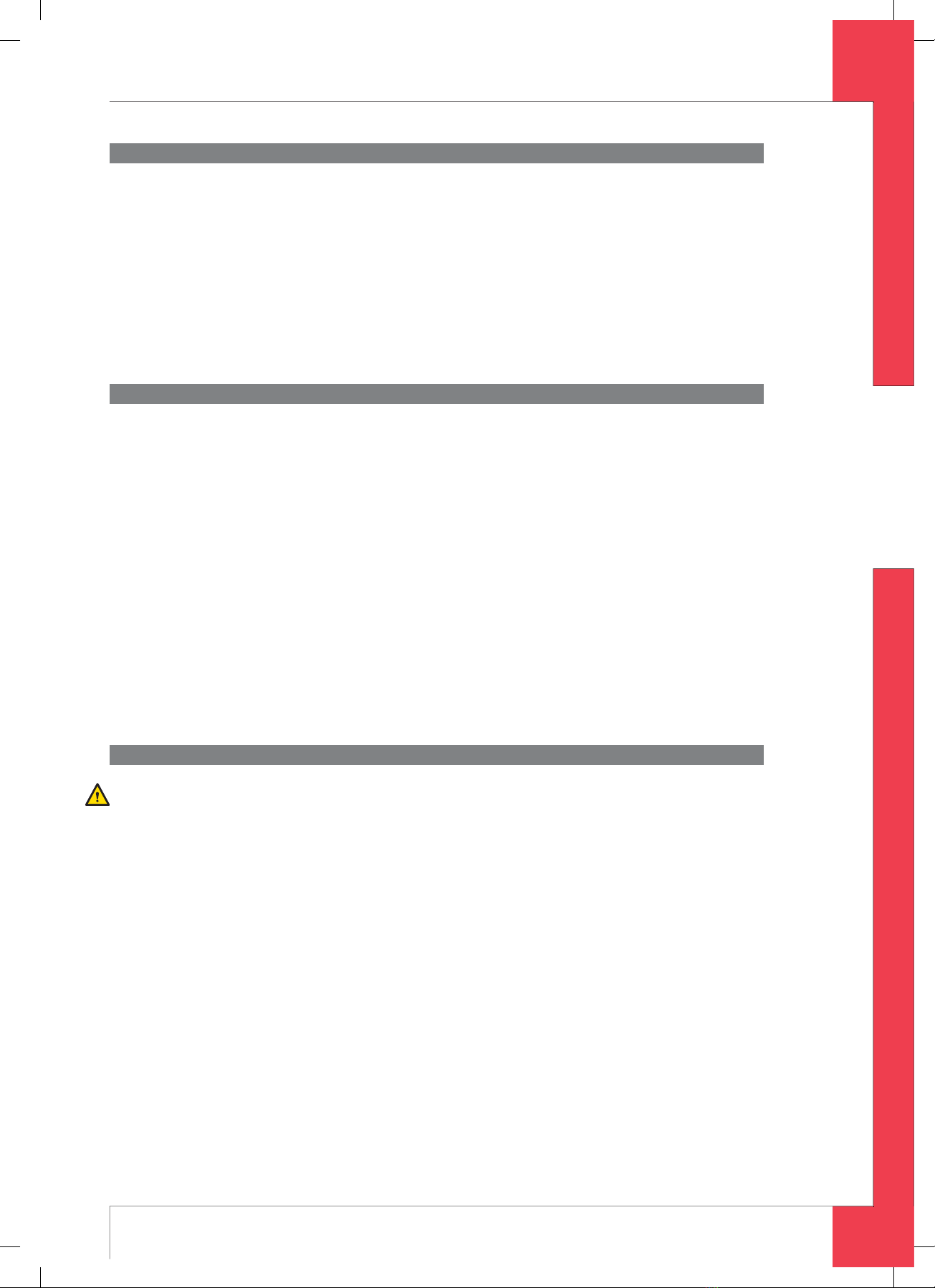
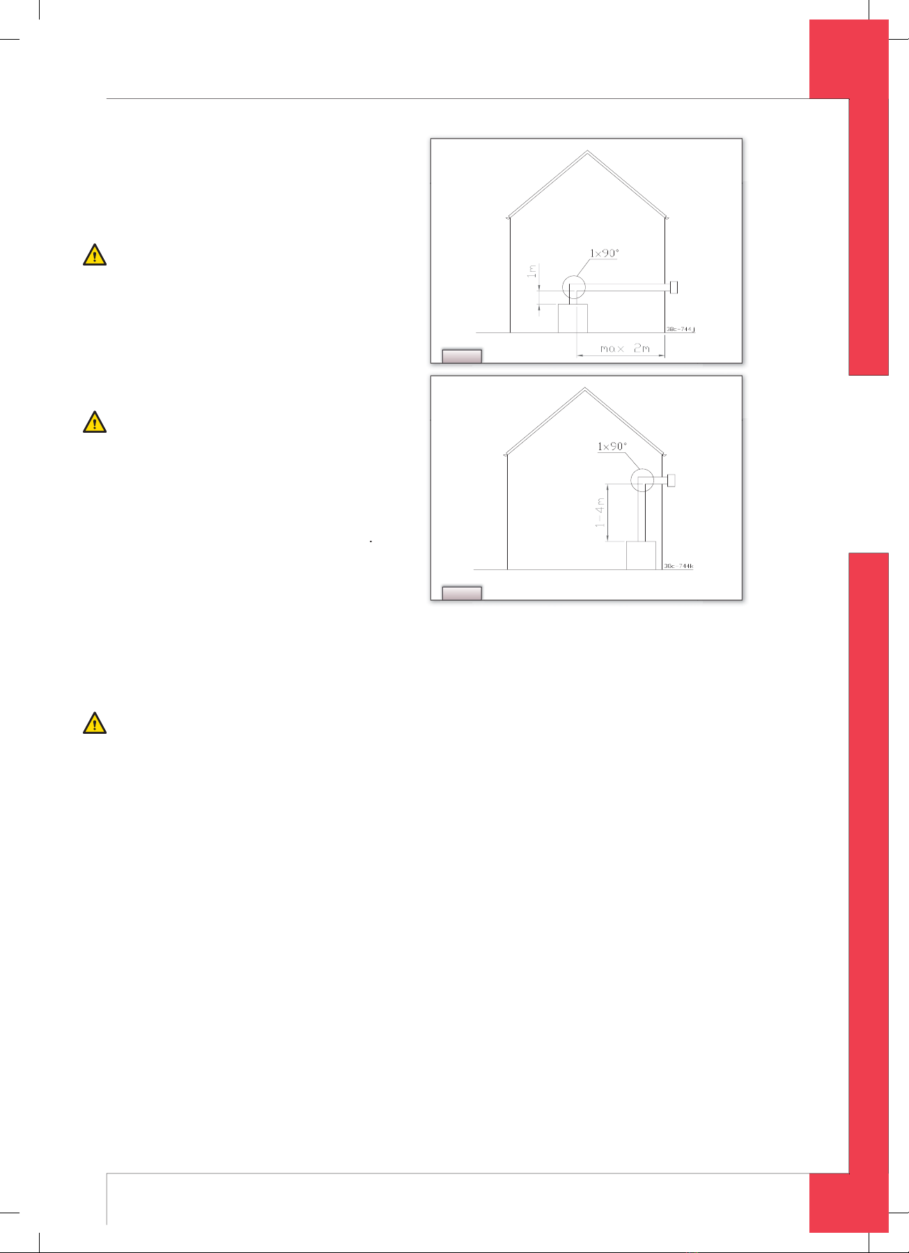
.5.3.2 Placing concentric system with roof duct
The roof duct can end in a slopin
and a flat roof
The roof duct can be supplied with an adhesive plate for a flat roof or with a universally ad
ustable tile for a sloping
roo
Place the concentric s
stem as follows
- Maintain a distance o
at least 50 mm between the outside o
the concentric system and the walls and/or the ceiling.
If the system is built in (for instance) a cove, it should be made with incombustible material all around it
Use
eat-resistant iso
ation materia
w
en passing t
roug
com
usti
e materia
.
Cautio
Some heat-resistant isolation materials contain volatile com
onents that will s
read an un
leasant smell for a
ro
onge
time; t
ese are not suita
e.
➠
Build the system up
rom (the connection stump o
) the appliance.
➠
Connect the concentric pipe pieces and, if necessary, the bends
➠
On eac
connection, app
a c
ip
in
ing wit
si
icon sea
ing ring.
➠
Use a parker to
x the clip bindin
to the pipe on locations that cannot be reached a
ter installation.
➠
Apply sucient clamps, so that the weight of the pipes does not rest on the appliance
➠
Determine the remaining length o
the roo
duct.
➠
Make sure the roo
duct has the ri
ht dimensions
Cautio
Ma
e sure t
at t
e rig
t insertion
engt
is maintaine
➠
Connect the roo
duct to the concentric
i
es
Cautio
- Make sure that the universal tile
ts well with the surroundin
tiles
Make sure that the adhesive
late ts well onto the at roof.
.5.4 Connection of existing chimney flu
It is possible to connect the appliance to an existin
channel
A flexible SS pipe is placed in the chimne
for dischar
in
flue
ases. The surroundin
space is used to suppl
com
ustion air
The followin
requirements appl
when connectin
to an existin
chimne
flue:
- onl
allowed when used in combination with the special DRU chimne
installation set. The installation re
ulation
is a
so supp
ie
- the dimensions should be at least 1
0 x 1
0 mm
- the vertical len
th has a maximum of 12 meters
- the horizontal length has a maximum o
3 meters
- the existin
chimne
flue has to be clean
- the existin
chimne
flue has to be closed
For setting the appliance, the same conditions/instructions apply as
or the concentric system described above.
6.6 Placing the chimne
breast
T
e app
iance is
esigne
to
e mounte
tig
t
y in a new c
imney
reast
In order to provide proper heat dischar
e, there should be sufficient space around the appliance.
The chimne
breast should be ventilated sufficientl
b
means of ventilation holes.
I
the chimney breast is made o
stone-like material, it is necessary to place a mantel iron (
or this, see section
6.6.1
- use incombustible and heat resistant material
or building the chimney breast, including the back wall, inside and
top of the chimney breast
The ventilation holes - which should be mounted as high as possible - should have a combined passage o
at least
m
Cautio
When placing the chimne
breast,
ou should take the
ollowing into account (see fi g . 3
:
the narrow
an
es o
the appliance’s mountin
rame
the location of the control box: it should be placed with a distance of 850 mm to the left or to the right of the appli
ance - as
ow as
ossi
e
the measurements o
the control box; see Placin
the Control Box section 6.7;
the location of the ventilation holes
the measurement o
the panes, so that the
can be placed/removed a
ter placing the chimne
breast
the protection o
the
as control block and the pipes a
ainst cement and plaster
UK
95901000UK Install_UK.indd 1095901000UK Install_UK.indd 10 16-04-2008 12:14:0716-04-2008 12:14:07