DryAIR HRA 4000 User manual

Operators Manual
Hose Reel
Model HRA 4000 / HRA 6000
S.N. 1643-01 -
DRYAIR Manufacturing Corp.
Box 126, 400 Service Road
St. Brieux, SK, Canada
S0K 3V0
Tel: (306) 275-4848 1-888-750-1700
Fax (306) 275-4664


Table of Contents
1. Introduction HRA Hose Reel .................................................................................................................. 1-1
Operating Features..................................................................................................................................... 1-1
Drive Features & Power Requirements .................................................................................................... 1-1
Electrical Precautions ............................................................................................................................... 1-1
Extension Cord Selection ...................................................................................................................... 1-2
Transportation & Storage ......................................................................................................................... 1-2
2. Setup/Operation ................................................................................................................................ 2-1
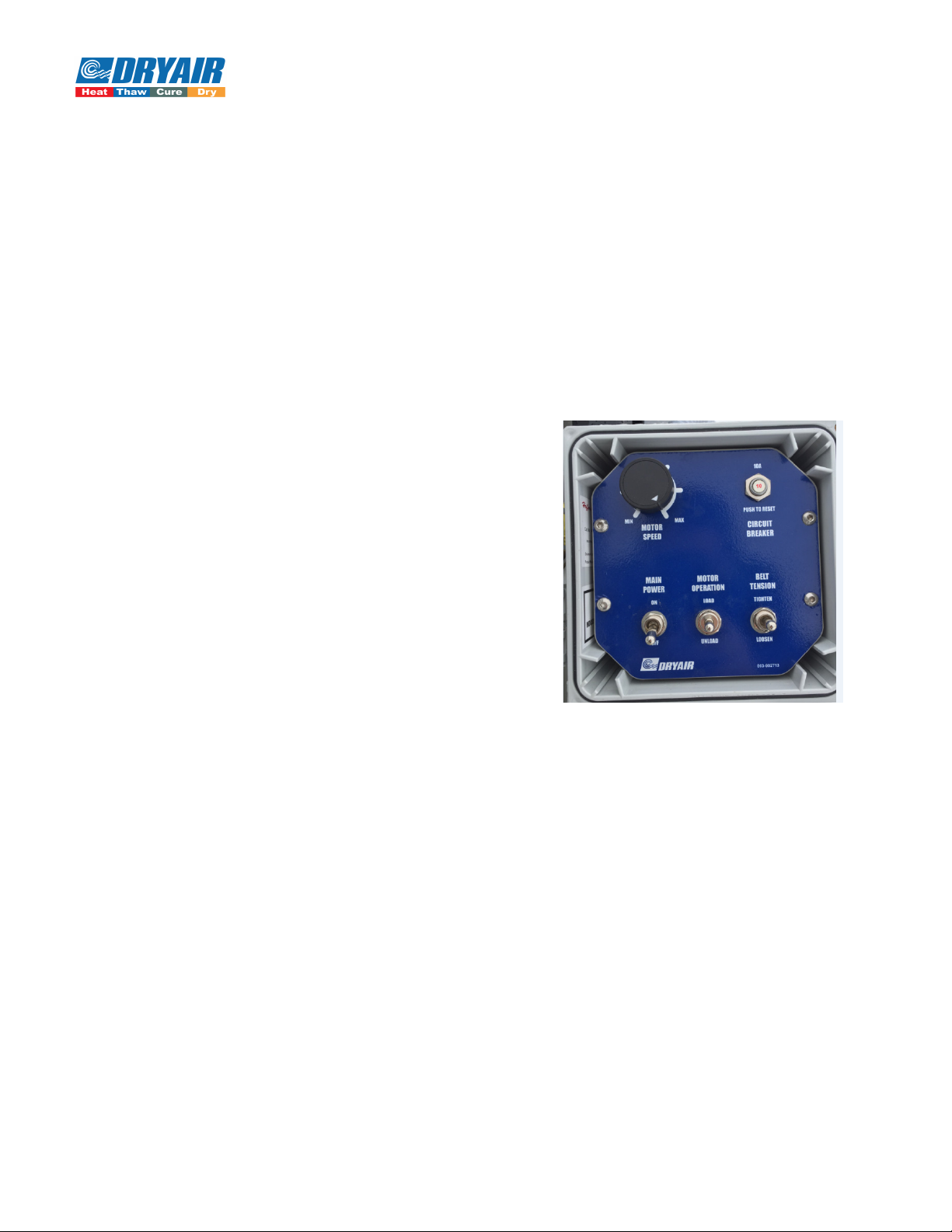
Manual Controls ....................................................................................................................................... 2-1
Reel Power ............................................................................................................................................ 2-1
Reel Direction Modes............................................................................................................................ 2-1
Mechanical Drive Components ................................................................................................................ 2-2
Electric Motor ....................................................................................................................................... 2-2
Gear Box ............................................................................................................................................... 2-3
Torque Limiter Clutch........................................................................................................................... 2-4
3. Maintenance...................................................................................................................................... 3-1
Precautions ............................................................................................................................................ 3-1
Auto Resets ........................................................................................................................................... 3-1
Manual Resets ....................................................................................................................................... 3-1
Electric Motor........................................................................................................................................... 3-1
Gear Box................................................................................................................................................... 3-2
Maintenance & Operation ..................................................................................................................... 3-2
Oil Filling Procedure ............................................................................................................................ 3-2
Break-In Period ..................................................................................................................................... 3-2
Torque Limiter Adjustment ...................................................................................................................... 3-2
Physical Check ...................................................................................................................................... 3-3
Torque Adjust Procedure ...................................................................................................................... 3-3
Run-in Procedure................................................................................................................................... 3-3
4. Appendix........................................................................................................................................... 4-1
Electrical Schematic ................................................................................................................................. 4-1

Table of Figures
Figure 1-1: Hose Reel .................................................................................................................................. 1-1
Figure 1-2: Outlet Adapter Use.................................................................................................................... 1-1
Figure 2-1: Control Panel............................................................................................................................. 2-1
Figure 2-2: Electric Motor ........................................................................................................................... 2-2
Figure 2-3: Gear Box ................................................................................................................................... 2-3
Figure 3-1: Gear Box Oil Filling Procedure ................................................................................................ 3-2
Figure 4-1:Electrical Schematic................................................................................................................... 4-1

Table of Tables
Table 1: Electric Motor Features & Data..................................................................................................... 2-2

1-1
Introduction HRA Hose Reel
1.Introduction HRA Hose Reel
Operating Features
*DANGER! It is very important that you read and understand
this manual before operating the reel! Failure to follow the
procedures and cautions in this manual could lead to injury or
possible death! *
The DRYAIR hose reel’s primary purpose is dispense and collect
fluid circulation hose on job sites; primarily with respect to
ground thaw and/or concrete cure operations.
The hose reel (see at right in Figure 1-1) includes the following
controls
•Spool directional controls
•Momentary foot switch for Load or Unload application.
•Hose Reel drive speed
•Degree of drive engagement/braking
Drive Features & Power
Requirements
•The reel can be run off an 115VAC, 15 Amp circuit.
•Reel power and directional control is handled through two toggle switches. One controls Power -
On/Off, the other controls the Mode - Load/Unload.
•The reel motor is a permanent magnet, direct-current, high-torque, 1HP motor capable of variable
speed operation. The reel operates between 5 RPM and 15 RPM. This is adjusted by the MOTOR
SPEED control dial.
•Drive and motor protection against inertial forces is provided by an adjustable torque-limiter clutch
located between the motor/gear box and the reel spool. An adjustable torque-limiter clutch located
between the motor/gearbox and the reel spool provides additional protection against high inertial
load as well as offering a degree of safety against entanglement.
Electrical Precautions
•Take care to not unplug the unit by pulling on the cord. To
unplug, grasp the plug, not the cord.
*CAUTION! Do not operate unit if the power supply cord or plug
is damaged! Inspect all cords before operating the unit. *
•This appliance is for use on a nominal 120V circuit, and has a
grounding plug that looks like the plug illustrated Sketch A in
Figure 1-2. A temporary adaptor, which looks like the
adaptors illustrated in Sketches B and C, may be used to
connect this plug to a 2-pole receptacle as shown in Sketch B if
a properly grounded outlet is not available. The temporary adaptor should be used only until a
properly grounded outlet can be installed by a qualified electrician. The grounding means (lug,
Figure 1-1: Hose Reel
Figure 1-2: Outlet Adapter Use

1-2
Introduction HRA Hose Reel
rigid ear, etc.) on the adaptor must be connected to a permanent ground such as a properly
grounded outlet box cover. This connection must be made with a metal screw.
Extension Cord Selection
An extension cord may be necessary to operate the unit. Keep the following precautions in mind when
selecting a cord.
•The marked electrical rating of the cord should be at least as great as the electrical rating of the
appliance.
•The extension cord used should be a grounding type, 3-wire (3 prong) cord.
•Do not drive, drag, or place objects over extension cords.
•Cords rated for indoor used should not be used outdoors.
•Note that the extension cord connection should be kept dry and off of the ground. Store all cords
indoors when not in use, wherever possible.
*DANGER! Keep out of reach of children. *
*CAUTION! Do not clean this unit with a water spray or similar. *
Transportation & Storage
•The reel can be transported by common carrier. The reel can be loaded using a forklift.
•A transport trailer is also available with a heat unit.
•If the reel is remote and not connected to the heating system, it can be stored out of the way or off
the site when it is not needed.

2-1
Setup/Operation
2.Setup/Operation
*DANGER! It is very important that you read and understand this section before operating the
hose reel! Failure to follow the procedures and cautions in this manual could lead to injury or
possible death! *
Manual Controls
The Hose Reel has a master power switch, a motor direction switch, a belt tension switch, a motor
speed dial, and a circuit breaker. These controls can all be found on the Control Panel (seen below in
Figure 2-1).
*CAUTION! When NOT operating the reel, put the reel Main Power Switch toggle switch in the “Off”
position to prevent accidental activation and possible injury. When the hose reel is to be left
unsupervised, the power cord should be unplugged from the
power supply. *
Reel Power
Power is present when the MAIN POWER switch is in the
“ON” position. The motor is operated by depressing the foot
switch, which operates a momentary contact (will only
operate when depressed).
Reel Direction Modes
Mode 1 – Powered Load
Mode 2 – Freewheeling Unload
Mode 3 – Powered Unload
Mode 4 – Cold Starting
*CAUTION! Take care not to allow your hands, feet or
clothing to become trapped in any of the reel’s moving mechanisms. *
Mode 1 – Powered Load
The LOAD mode is achieved by the mode toggle switch is in the LOAD position and the
belt is sufficiently tightened to transmit power from the motor/gearbox to the hose reel
spool.
The foot switch is momentary and will only operate when it is depressed.
The hose must be directed manually into position on the hose reel.
The hose reel speed may be varied by means of the MOTOR SPEED dial.
Mode 2 – Freewheel Unload
The BELT TENSION switch controls the linear actuator which positions the pivot arm, on
the end of which is an idler sheave that depresses the drive belt. This adjusts the belt
tension. With the belt loosened the hose reel may freewheel.
It is important to maintain sufficient tension on the belt to allow a degree of braking on the
hose reel spool while unrolling hose. The hose reel spool possesses a variable amount of
inertia depending on its mass and its angular velocity. This necessitates gradually loosening
the belt as the hose is unloaded: less spool inertia (from decreased mass) requires less
braking.
Figure 2-1: Control Panel

2-2
Setup/Operation
Note that for transport of the hose reel it is advisable to maintain sufficient tension on the
hose reel to arrest any rotation of the hose reel spool caused by motion of the unit.
Mode 3 – Powered Unload
The UNLOAD mode is achieved by the mode toggle switch is in the UNLOAD position
and the belt is sufficiently tightened to transmit power from the motor/gearbox to the hose
reel spool.
The foot switch is momentary and will only operate when it is depressed.
Mode 4 – Cold Starting
It is advisable that when beginning operation below 18
o
F (-8
o
C) that the belt tension be
temporarily loosened far enough that motor rotation will not cause spool rotation and that
the motor be powered for a minimum of 5 minutes. This will allow the oil in the gearbox to
warm up and to allow smooth low-temperature operation.
Following system warm-up re-tension the belt and begin your desired operation.
Mechanical Drive Components
Access to the internal mechanical drive components (Figure 2-2) is
through the access door. This door must be removed.
Electric Motor
•No regular maintenance is required.
•Low temperature automatic reset thermal protector.
•Totally enclosed and fully gasketed construction for dirty
environments.
•Make sure that, during operation or storage, the motor is not
in prolonged contact with moisture.
•Refer to the chart “Table 1- Electric motor features & data”,
below for motor data.
Table 1: Electric Motor Features & Data
PRODUCT FEATURE - ENCLOSED HIGH TORQUE PMDC MOTOR
Model Number: MPTM-001-1L18 Weight: 29 Lbs
Power: 1 HP Torque: 2.92 Ft*Lbs.
ω: 1800 RPM Housing Rating: TEFC
Voltage: 90VDC Insulation Class: F
Frame: NEMA 56C Output Shaft: 5/8’’
Mounting: C-FACE Service Factor: 1.0
Figure 2-2: Electric Motor

2-3
Setup/Operation
Gear Box
The gear box can be seen below in Figure 2-3.
•Helical worm gear reducer.
•60:1 gear reduction.
•5/8’’ input shaft size.
•1 1/8’’ output shaft size.
*CAUTION! Do not operate the unit without ensuring it contains the correct amount of oil. Do not
overfill or under fill with oil. Injury to personnel, unit, or other equipment may result.
Oil should be changed with greater frequency if unit is used in severe environment (dusty or high
humidity). *
*CAUTION! Oil, housing, and other components can reach high temperatures during operation, and can
cause severe burns. Use extreme care when removing lubrication plugs and vents while servicing the unit.
See “Maintenance - Gear Box” section of the Operators Manual for Gear Box oil filling procedures,
service & maintenance. *
Figure 2-3: Gear Box

2-4
Setup/Operation
Torque Limiter Clutch
•The Torque limiter protects the drive line from damage due to overload conditions. The driven center
member slips on non- asbestos friction discs during overload situations in the drive line.
•Torque Ratings
- Minimum: 60 lb.-ft.
- Maximum: 190 lb.-ft.
Please note that the torque ratings are estimates. Actual torque capacity may vary significantly
depending on many factors. Field conditions such as oil, humidity, water and temperature as well
as the frequency and duration of slippage all affect torque capacity. Although the torque limiter
clutch is factory set at Dryair, periodic adjustment may be required. It is recommended the torque
setting of the clutch be checked twice per season (see “Maintenance” section). With prolonged
use, the two friction disks, located on either side of the A-plate sprocket, will eventually show
wear.
• It is important that the torque limiter clutch is adjusted properly. The clutch should be set to a slip
torque of 100 Ft*Lbs.
*Note: A visual check may be required to confirm whether it is the clutch that is slipping or the motor. (
See “Maintenance - Torque limiter adjustment” section of the Operator’s manual for Torque Adjustment
& Run-In Procedure.) *

3-1
Maintenance
3.Maintenance
*DANGER! It is very important that you read and understand this section before operating the
hose reel! Failure to follow the procedures and cautions in this manual could lead to injury or
possible death! *
Precautions
Electric shock will result in death or serious injury.
•The user is responsible for conforming to all applicable code requirements with respect to grounding
all equipment.
•Many parts in this drive controller, including printed wiring boards, operate at line voltage. DO
NOT TOUCH. Use only electrically insulated tools.
•DO NOT touch unshielded components or terminal strip screw connections with voltage present.
•Install and close all covers before applying power or starting and stopping the hose reel.
•Before servicing:
oDisconnect all power.
oPlace a “DO NOT TURN ON” label on the drive controller disconnect.
oLock the disconnect in the open position.
•Disconnect all power including external control power that may be present servicing the drive
controller.
Auto Resets
The drive controller is factory set and will reload its factory default settings each time the AC line is
connected. It will also automatically start when recovering from a series of different faults.
Manual Resets
If a fault occurs due to a prolonged overload, overvoltage, undervoltage or phase failure, the control
must be manually restarted. The control can be restarted by:
1) Disconnect AC power and wait for at least 30 seconds for drive controller to power down.
2) Reconnect the AC power. This will re-initiate the factory default settings.
Electric Motor
•No regular maintenance is required.
•Make sure that the motor is not in prolonged contact with
moisture during operation or storage.

3-2
Maintenance
Gear Box
Maintenance & Operation
*CAUTION! Oil, housing, and other components can reach high temperatures during operation, and can cause
severe burns. Use extreme care when removing lubrication plugs and vents while servicing the unit. *
• Do not operate the unit without making sure it contains the correct amount of oil. Do not
overfill or under fill with oil, or injury to personnel, unit, or other equipment may result.
• For proper operation in subzero conditions, it is mandatory that the following oil be used:
“Spartan EP 320 industrial gear oil” (or equivalent)
…any other gear oil will void warranty!
Oil Filling Procedure
•Remove Fill and Vent plugs (see Figure 3-1 for locations).
•Clean threads on the removed plugs and the plug holes with degreaser.
•Fill gear box with the recommended lubricant (see above) to a level near the center line of the
uppermost horizontal shaft or until lubricant comes out of the oil level plug hole.
•Install plugs secure in gear case.
Break-In Period
After the first 100 hours of operation, drain out initial oil, flush out the gear case with an approved non-
flammable, non-toxic solvent, such as Whitmore’s Flushing Oil (#06802030) or Medallion Flushing Oil
Kosher (#06812010), and refill. Thereafter, oil should be changed at least every 2500 operating hours or
every 6 months - whichever occurs first.
*Note: Oil should be changed with greater frequency if unit is used in severe environments (dust or high
humidity). *
Torque Limiter Adjustment
•Although the torque limiter clutch is factory (Dryair) set, periodic adjustment may be required. It is
recommended that the torque setting of the clutch be checked twice a season. With prolonged use,
the two friction disks, located on either side of the A-plate sprocket, will eventually show wear.
•It is important that the torque limiter clutch is adjusted properly. If the clutch slips too easily, the
spool will take too long to stop and hose will pile up on the reel. If the clutch does not slip at all,
Figure 3-1: Gear Box Oil Filling Procedure

3-3
Maintenance
the protection on the motor controller or belt will take over and the spool will again take too long
to stop.
*Note: A visual check may be required to confirm whether it is the clutch that is slipping or whether it
is the motor controller or belt that is automatically adjusting in an overload situation. *
•Check that the clutch is adjusted properly with the following procedure:
Physical Check
•With no power being applied to the reel, grip the edge of the spool plate and apply full upward force,
making sure that you are lifting with your legs and not your back.
•You should be able to cause the clutch to just slip with full lifting force.
•If the clutch does not slip or slips too easily, refer to the “torque adjust procedure”, below.
Torque Adjust Procedure
•Insure that the adjusting nut is in a finger tight position.
•If the adjustment nut is tighter than finger tight, loosen and complete previous step.
•Match mark the adjusting nut with the hub. Using a torque wrench tighten the adjusting nut to
90ft*lb.
After the break-away torque is set, bend the tabs of the lock washer over the hex flats of the adjusting
nut.
*Note: The torque limiter clutch nut requires a reasonable amount of force to adjust. Use a torque
wrench that provides you with at least 18” of leverage. *
Run-in Procedure
•If the torque has been taken apart and reassembled or friction disks have been changed, it is
recommended that the clutch be “run in” by “slipping” the center member (sprocket).
•Insure that the adjusting nut is in a finger tight position.
•Match mark the adjusting nut and hub. Advance the adjusting nut ¼ turn from finger tight.
•Slip the torque limiter sprocket for 8 minutes at full RPM.
•Refer back to the “Torque adjust procedure” for final
readjustment.

4-1
Appendix
4.Appendix
Electrical Schematic
See below the electrical schematic for the HRA Hose Reel.
Figure 4-1:Electrical Schematic
This manual suits for next models
1
Table of contents
Other DryAIR Tools manuals