South NTS-960R User manual
Operation Manual
NTS-960R Series
Electronic Total Station
SOUTH SURVEYING &MAPPING INSTRUMENT CO., LTD

INDEX
FOREWORD..............................................................................................................................................1
PRECAUTIONS.........................................................................................................................................2
SAFETY GUIDE ........................................................................................................................................3
1. NOMENCLATURE AND FUNCTIONS..............................................................................................4
1.1 NOMENCLATURE............................................................................................................................4
1.2 KEYPAD ............................................................................................................................................6
2. SYNCHRONIZATION WITH PC........................................................................................................7
2.1 INSTALLATION MICROSOFT ACTIVESYNC...............................................................................7
2.2 CONNECTING TOTAL STATION WITH PC ...................................................................................7
3. KNOWINGABOUT WINCE(R) ..........................................................................................................9
3.1 OPERATING SYSTEM......................................................................................................................9
3.2 SETTING YOUR TOTAL STATION .................................................................................................9
3.2.1 Backlight .....................................................................................................................................9
3.2.2 Touch-screen Adjustment ..........................................................................................................11
3.3 APPROACHES TO INPUT NUMERALAND CHARACTER........................................................12
4.STAR KEY (★) MODE.....................................................................................................................16
5. PREPARATION FOR MEASUREMENT .........................................................................................18
5.1 UNPACKING AND STORE OF INSTRUMENT ............................................................................18
5.2 INSTRUMENT SETUP....................................................................................................................18
5.3 BATTERY INFORMATION ............................................................................................................21
5.4 REFLECTOR PRISM.......................................................................................................................22
5.5 MOUNTING AND DISMOUNTING INSTRUMENT FROM TRIBRACH ...................................22
5.6 EYEPIECE ADJUSTMENT AND COLLIMATING OBJECT ........................................................23
5.7 VERTICAL AND HORIZONTALANGLE TILT CORRECTION...................................................24
6. BASIC SURVEY...................................................................................................................................25
6.1 ANGLE MEASUREMENT..............................................................................................................26
6.1.1 Horizontal Angle (Right Angle) and Vertical Angle Measurement ...........................................26
6.1.2 Switch Horizontal Angle Right/Left..........................................................................................27
6.1.3 Horizontal Angle Reading Setting.............................................................................................28

6.1.4 Vertical Angle Percentage (%) Mode ........................................................................................30
6.1.5 Repeat Angle Measurement.......................................................................................................31
6.2 DISTANCE MEASUREMENT........................................................................................................33
6.2.1 Setting Atmosphere Correction .................................................................................................34
6.2.2 Atmospheric Refraction And Earth Curvature Correction.........................................................37
6.2.3 Setting Target Type....................................................................................................................38
6.2.4Setting the Prism Constant .........................................................................................................39
6.2.5Distance Measurement (Continue Measurement) ......................................................................40
6.2.6 Distance Measurement (Single/N-Time Measurement) ............................................................41
6.2.7Fine/Tracking Measurement Mode.............................................................................................42
6.3 COORDINATE MEASUREMENT..................................................................................................43
6.3.1 Setting Coordinate Values of Occupied Point ...........................................................................43
6.3.2 Setting the Backsight Point .......................................................................................................45
6.3.3 Setting the Instrument Height/ Prism Height.............................................................................46
6.3.4 Operation of Coordinate Measurement .....................................................................................47
7.APPLICATION PROGRAMS.............................................................................................................48
7.1 LAYOUT ..........................................................................................................................................48
7.2 REMOTE ELEVATION MEASUREMENT (REM) ........................................................................49
7.2.1 Inputting Prism Height (h).........................................................................................................50
7.2.2 without Inputtingt Prism Height................................................................................................51
7.3 MISSING LINE MEASUREMENT (MLM) ....................................................................................53
7.4 LINE MEASUREMENT (LINE)......................................................................................................56
7.5 LEAD MEASUREMENT (STORE NEZ) ........................................................................................59
7.6 OFFSET MEASUREMENT (OFFSET) ...........................................................................................62
7.6.1 Angle Offset ..............................................................................................................................62
7.6.2 Distance Offset ..........................................................................................................................64
7.6.3 Column Offset ...........................................................................................................................65
7.6.4 Plane Offset ...............................................................................................................................67
7.7 PARAMETERS SETTING ...............................................................................................................69
8. START STANDARD SURVEY PROGRAM......................................................................................71
9. PROJECT .............................................................................................................................................74
9.1 CREATE NEW PROJECT................................................................................................................75
9.2 OPEN PROJECT ..............................................................................................................................76
9.3 DELETE PROJECT..........................................................................................................................76
9.4 OPTION............................................................................................................................................78
9.5 GRID FACTOR ................................................................................................................................79

10. DATA EXPORT/IMPORT.................................................................................................................80
10.1 DATA EXPORT ..............................................................................................................................80
10.2 DATA IMPORT...............................................................................................................................82
11. RECORD MEASUREMENT DATA.................................................................................................84
11.1 SETTING OCCUPIED POINT AND BACKSIGHT POINT..........................................................85
11.2 BACKSIGHT OBSERVATION (BS OBS) .....................................................................................96
11.3 FORESIGHT OBSERVATION (FS OBS).......................................................................................97
11.4 SIDESHOT OBSERVATION (SS OBS) .........................................................................................99
11.4.1 Offset .....................................................................................................................................101
11.4.2 Plane Offset ...........................................................................................................................104
11.4.3 Pt. Line Mode (For Measurement from Point to Line) ..........................................................106
11.4.4 Control Input .........................................................................................................................108
11.5 CROSS SECTION SURVEY........................................................................................................109
12. EDIT DATA.......................................................................................................................................112
12.1 EDITING RAW DATA .................................................................................................................113
12.2 COORD. DATA ............................................................................................................................115
12.2.1 Edit Coord. Data....................................................................................................................115
12.2.2 Add coord. data......................................................................................................................117
12.2.3 Delete Coord. Data ................................................................................................................118
12.3 FIXED POINT DATA ...................................................................................................................119
12.4 CODE DATA ................................................................................................................................119
12.4.1 Create New Layer..................................................................................................................119
12.4.2 Edit Layer/Code ....................................................................................................................121
12.4.3Delete Code ............................................................................................................................122
12.5 FILL-CUT DATA .........................................................................................................................123
13. PROGRAM MENU..........................................................................................................................124
13.1 SET OUT ......................................................................................................................................124
13.1.1 Occupied Point& Backsight Point.........................................................................................124
13.1.2 Point Set Out .........................................................................................................................126
13.1.3 String Setout ..........................................................................................................................130
13.2 ROAD DESIGN AND LAYOUT..................................................................................................131
13.2.1 Define Horizontal Alignment ................................................................................................131
13.2.2 Edit Alignment ......................................................................................................................137
13.2.3 Define Vertical Alignment .....................................................................................................139
13.2.4 Edit Vertical Alignment .........................................................................................................140
13.2.5 Alignment Setout...................................................................................................................142

13.2.6 Slope Setout...........................................................................................................................145
13.2.7 Cross Section Setout..............................................................................................................148
13.3 COGO...........................................................................................................................................150
13.3.1 Intersection ............................................................................................................................150
13.3.2 4-Intersection.........................................................................................................................151
13.3.3 Inverse ...................................................................................................................................153
13.3.4 Area .......................................................................................................................................154
13.3.5 Missing Line Measurement ...................................................................................................157
13.3.6 Radiate...................................................................................................................................159
13.4 TRAVERSE ADJUSTMENT........................................................................................................160
13.5 BATTER BOARDS ......................................................................................................................167
13.5.1 Method 1: Batter board using two sides ................................................................................167
13.5.2 Method 2: Batterboards using one side .................................................................................170
13.6 TAPE DIMENSIONS ...................................................................................................................172
14. SYSTEM SETTINGS.......................................................................................................................175
14.1 SETTING UNIT AND MEASURING PARAMETER .................................................................175
14.2 SETTING ATMOS P H ERE DATAAND PRISM CONSTANT.....................................................178
15. CHECK AND ADJUSTMENT........................................................................................................180
15.1 PLATE VIAL ................................................................................................................................180
15.2 CIRCULAR VIAL........................................................................................................................180
15.3 INCLINATION OF RETICLE......................................................................................................181
15.4 PERPENDICULARITY BETWEEN LINE OF SIGHT AND HORIZONTAL AXIS (2C) ..........182
15.5 VERTICAL INDEX DIFFERENCE COMPENSATION..............................................................184
15.6 ADJUSTMENT OF VERTICAL INDEX DIFFERENCE (I ANGLE) AND SETTING VERTICAL
INDEX 0...............................................................................................................................................185
15.7 TRANSVERSE AXIS ERROR COMPENSATION ADJUSTMENT...........................................186
15.8 OPTICAL PLUMMET .................................................................................................................188
15.9 INSTRUMENT CONSTANT(K)............................................................................................189
15.10 PARALLEL BETWEEN LINE OF SIGHT AND EMITTING PHOTOELECTRIC AXIS.........191
15.11 TRIBRACH LEVELING SCREW .............................................................................................191
15.12 RELATED PARTS FOR REFLECTOR ......................................................................................191
16.ACCESSORIES................................................................................................................................193
【APPENDIX-A】.................................................................................................................................194
1EXPORT DATA FROM TOTAL STATION.......................................................................................194
1.1 Raw Data Format........................................................................................................................194
1.2 Coordinate Data Format .............................................................................................................194

2IMPORT DATA TO TOTAL STATION .............................................................................................195
2.1 Coordinate Data/Fixed Point Data Format .................................................................................195
2.2 Cross Section Data Format.........................................................................................................195
2.3 Point P Coding Format ...............................................................................................................196
2.4 Horizontal Line...........................................................................................................................196
【APPENDIX-B】CALCULATE ROAD ALIGNMENT ................................................................198
1ROAD ALIGNMENT ELEMENTS ..................................................................................................198
2CALCULATION ROAD ALIGNMENT ELEMENTS......................................................................200
TECHNICALSPECIFICATION..........................................................................................................205

1
FOREWORD
ThankyouforpurchasingElectronicTotalStationWinCE(R)Series.
AsanewgenerationoftotalstationindependentR&D,WinCESeriesrealizesthe
automationandinformationization,andtakestheadvantageofnetworks,which
makesitacomputer‐liketotalstation.
TheWindowsCEinterfaceofWinCE(R)SeriesismuchsimilartothatofWindows
System.Youcanintuitionallylaunchdatastoring,manipulatingandexchangingwithPC
basedonWindowsplatform.
Theuseofthemanual:WinCE(R)SeriesTotalStation.
1,WinCESeriesTotalStationwithinfraredEDM.
2,WinCE(R)SeriesTotalStationwithinfraredlaserEDM(visiblelaser,noprism)
Thecontentwith“ ”inthemanualappliesonlytoWinCE(R)SeriesTotalStation.
Pleasereadthemanualcompletelybeforeuseit.

2
PRECAUTIONS
1.Donotcollimatetheobjectivelensdirecttosunlightwithoutafilter.
2.Donotstoretheinstrumentinhighandlowtemperaturetoavoidthesuddenor
greatchangeoftemperature.
3.Whentheinstrumentisnotinuse,placeitinthecaseandavoidshock,dustand
humidity.
4.Ifthereisgreatdifferencebetweenthetemperatureinworksiteandthatinstore
place,youshouldleavetheinstrumentinthecasetillitadaptstothetemperatureof
environment.
5.Iftheinstrumenthasnotbeenusedforalongtime,youshouldremovethebattery
forseparatestorage.Thebatteryshouldbechargedonceamonth.
6.Whentransportingtheinstrumentshouldbeplacedinitscarryingcase,itis
recommendedthatcushionedmaterialshouldbeusedaroundthecaseforsupport.
7.Forlessvibrationandbetteraccuracy,theinstrumentshouldbesetupona
woodentripodratherthananaluminumtripod.
8.Cleanexposedopticalpartswithdegreasedcottonorlenstissueonly!
9.Cleantheinstrumentsurfacewithawoolenclothafteruse.Ifitgetswet,dryit
immediately.
10.Beforeworking,inspectthepower,functionsandindicationsoftheinstrumentas
wellasitsinitialsettingsandcorrectionparameters.
11.Unlesstheuserisamaintenancespecialist,donotattempttodisassemblethe
instrumentbyyourselfevenifyoufindtheinstrumentabnormal.

3
SAFETY GUIDE
ForinfraredlaserEDM(visiblelaser)
Warning:
ThetotalstationisequippedwithanEDMofalasergradeof3R/Ⅲa.Itisverifiedby
thefollowinglabels.
Overtheverticaltangentscrewsticksanindicationlabel“CLASSIIILASERPRODUCT”.
Asimilarlabelisstickedontheoppositeside.
ThisproductisclassifiedasClass3Rlaserproduct,whichaccordstothefollowing
standards.
IEC60825‐1:2001“SAFETYOFLASERPRODUCTS”.
Class3R/Ⅲalaserproduct:Itisharmfultoobservelaserbeamcontinuously.User
shouldavoidsightingthelaserattheeyes.Itcanreach5timestheemittinglimitof
Class2/IIwithawavelengthof400mm‐700mm.
Warning:
Continuouslylookingstraightatthelaserbeamisharmful.
Prevention:
Donotstareatthelaserbeam,orpointthelaserbeamtoothers’eyes.Reflectedlaser
beamisavalidmeasurementtotheinstrument.
Warning:
Whenthelaserbeamemitsonprism,mirror,metalsurface,window,etc.,itis
dangeroustolookstraightatthereflex.
Prevention:
Donotstareattheobjectwhichreflectsthelaserbeam.Whenthelaserisswitched
on(underEDMmode),donotlookatitontheopticalpathorneartheprism.Itis
onlyallowedtoobservetheprismwiththetelescopeoftotalstation.
Warning:
ImproperoperationonlaserinstrumentofClass3Rwillbringdangers.

4
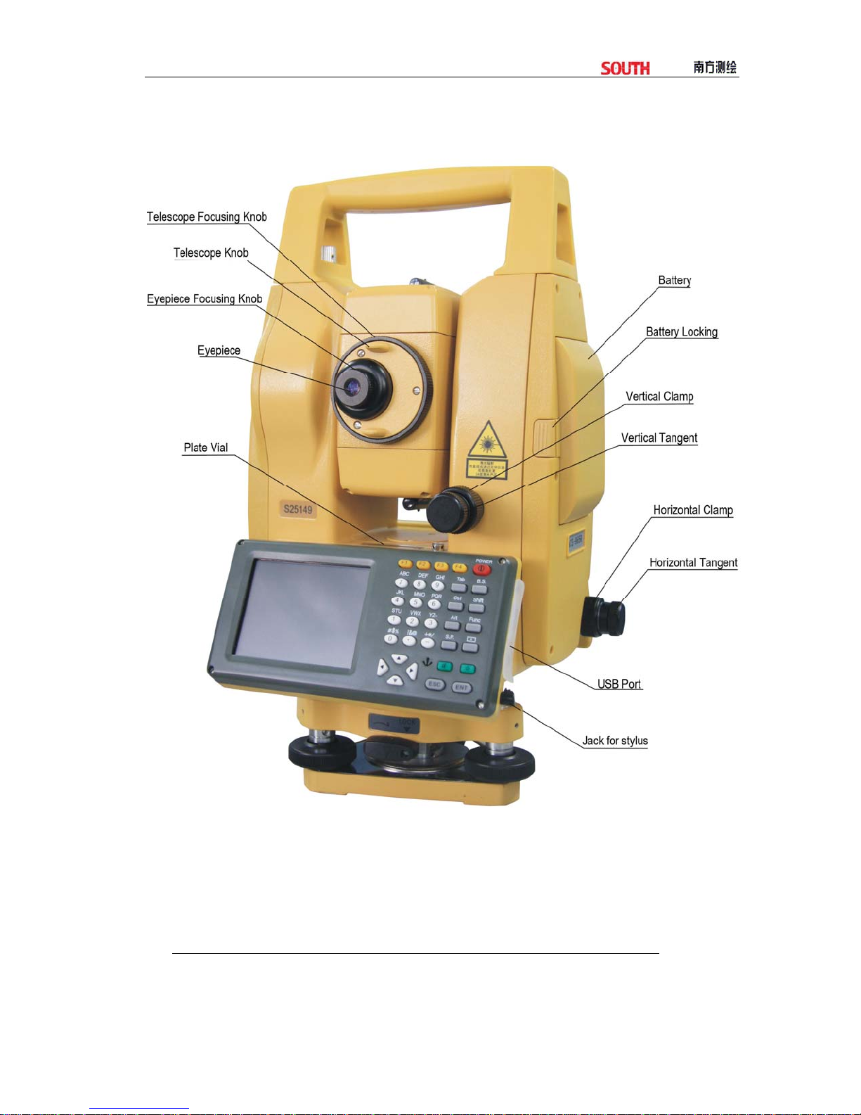
1. NOMENCLATUREAND FUNCTIONS
1.1 NOMENCLATURE
5
6
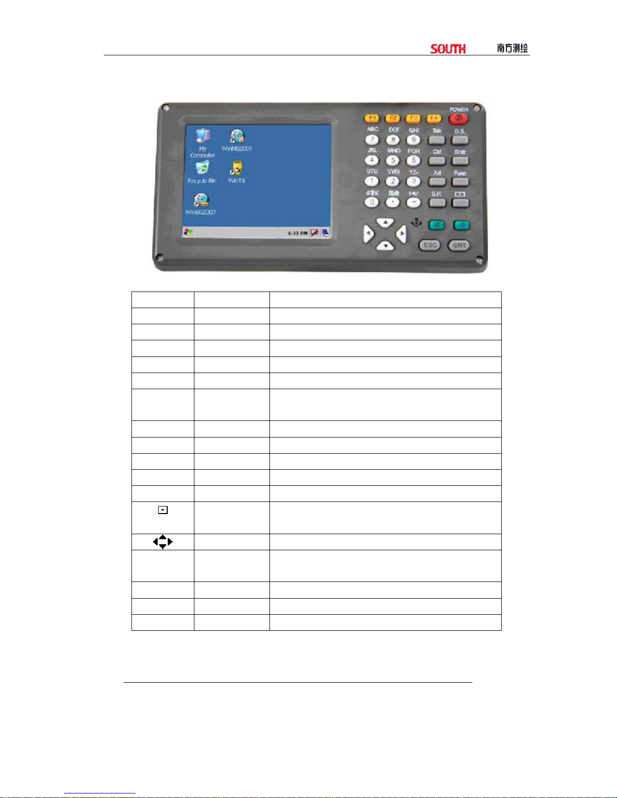
1.2 KEYPAD
FunctionsoftheKeys
Key Nomenclature Function
POWER Power Key To switch power ON/OFF.
F1~F4 Soft Key Refers to the function displayed.
0~9 Numeric Key To input desired numbers.
A~/ Alpha Key To input alphabets.
Tab Tab Key To move cursor rightward or to next character field.
B.S Backspace To delete one character leftward when inputting numbers or
alphabets.
Ctrl Ctrl Key Same as that on a PC.
Shift Shift Key Same as that on a PC.
Alt Alt Key Same as that on a PC.
Func Function Key To launch a specific function defined in the software.
S.P Space Key To input a space.
Inputting Panel
Key
To display inputting panel.
Cursor Key To move the cursor up/down/left/right.
αAlpha Shifting
Key
To shift to alphabet inputting mode.
★Star Key To launch several comer functions of the instrument.
ESC ESC Key Quit to previous display or previous mode.
ENT Enter Key To finish and accept the data input.

7
2. SYNCHRONIZATION WITH PC
2.1 INSTALLATION MICROSOFTACTIVESYNC
ThereisaCDofMicrosoftActiveSyncattachedintheproductpackage.First,
installMicrosoftActiveSynconthepersonalcomputerandcommunicatewithPDA.
Pleasefollowthestepsbelow.
BeforeInstallingMicrosoftActiveSync
Beforeinstalling,readthefollowingwordscarefully:
●Duringtheinstallationprocessing,rebootyourcomputerisrequired.Therefore,
pleasesaveyourjobsandquitalltheapplicationsbeforeinstallation.
●ToinstallMicrosoftActiveSync,youaresupposedtohaveanUSBcable
(availableintheproductpackage)connectthePDAwiththepersonalcomputer.
InstallationMicrosoftActiveSync
●PuttheCDintoyourdiskdrive.
MicrosoftActiveSyncInstallationGuidewillberunautomatically.Ifitisnotrun,
doubleclickonthe“setup.exe”undertherootmenuinthediskdrive.
●Click“Next”toinstallMicrosoftActiveSync.
2.2 CONNECTING TOTAL STATION WITH PC
AfterInstallingMicrosoftActiveSync,restartyourPC.
●PlugoneendoftheUSBcableintotheUSBportbesidethekeypadofthetotal
station,andanotherendintoonecommunicationportonyourPC.Fordetail,please,
refertoyourhardwaremanual.
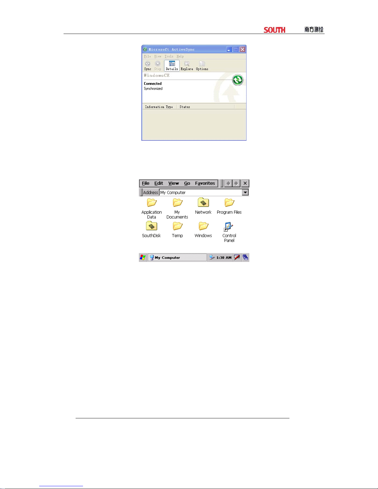
●Switchtotalstationon.ThesoftwarewilldetectthePDAandsetupthe
communicationport.Whenitisconnectedsuccessfully,thefollowingmessagewill
display.
8
Using“Browse”Function
AfterthesynchronizedbetweenthetotalstationandthePC,click“Browse”buttonto
browsealthecontentsintheportabledevice(totalstation),asbelow.
Youcanassignatasktoafilelikedeleteorcopy.

9
3. KNOWINGABOUT WINCE(R)
PressPOWERKeytoswitchiton,andenterintothewelcomeinterfaceofWinTotal
Station.
3.1 OPERATING SYSTEM
TotalStationWinCE(R)SeriesisbasedonWindowsCEoperatingsystem,which
similarizesyourbrowseapproachwiththatofMicrosoftWindowsonaPC.Youwill
findmanysimilarfunctionslikeStart,ShortcutFunctionListandToolsList,etc.
●Note:Whenthebatteryislow,anicon“ ”willappearonthestatusbar,as
wellasamessageshowingthatthebatteryislowwilldisplayedonthescreen.
3.2 SETTINGYOUR TOTAL STATION
YoucanadjustsettingofWinCE(R)toadaptyourworkstyle.
3.2.1 Backlight
Forsavebattery,totalstationWinCE(R)willjudgeautomaticallywhethertoshut
thelightornotandwilladjustlighteness.Youcansetasyouneed.
Howtosetthetimeofbacklight?
10
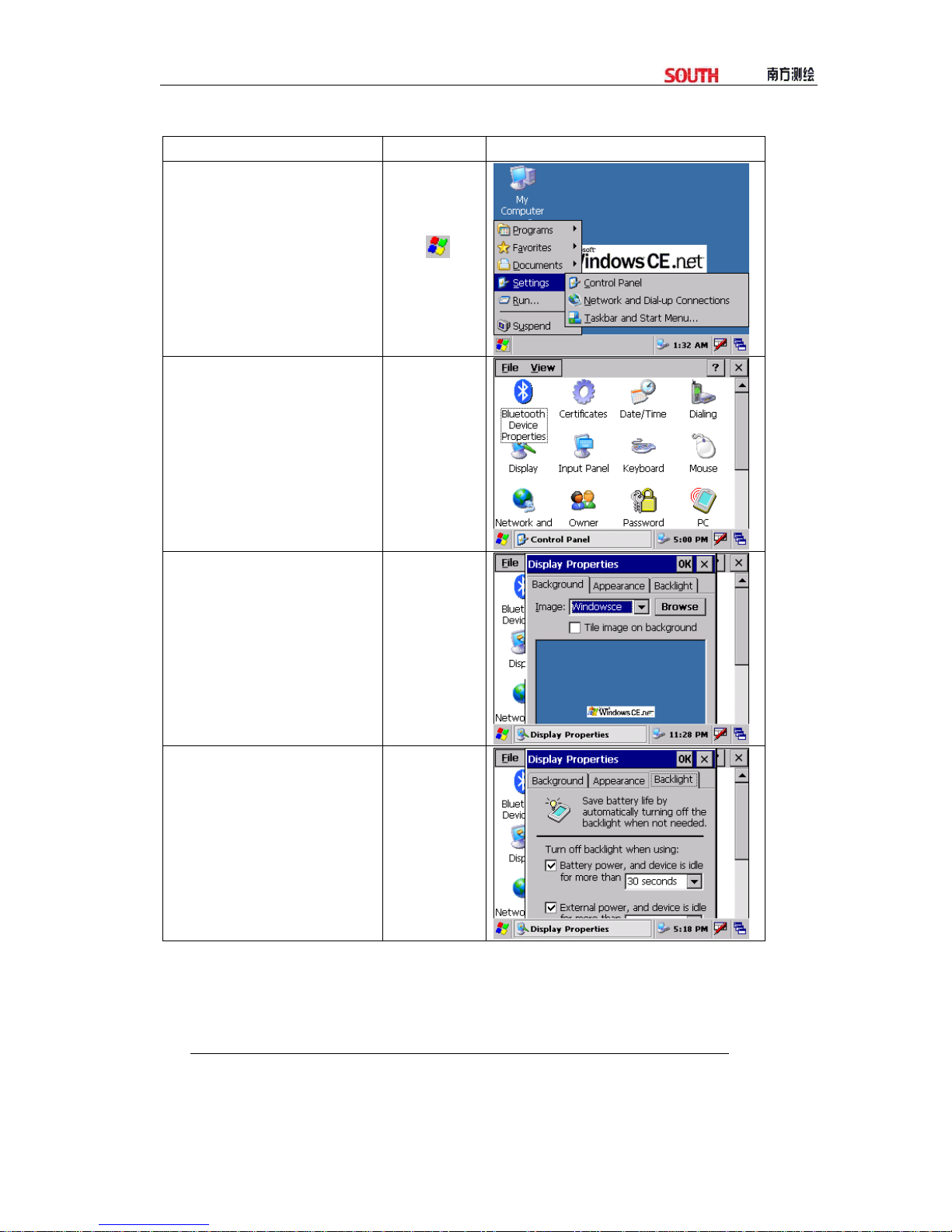
OPERATIONAL STEPS KEY DISPLAY
①On WindowsCE
desktop, click
“Start”→“Settings”.
+
Settings
②Press control panel to enter
into main menu. Use stylus to
roll the slider bar to find
“Display” icon.
Control panel
+
Display
③Click “Display” to enter
setting of Display Properties
④Click “Backlight”, a
function screen displays.
Choose the time of turning
off backlight to save battery.
After setting, press [OK] to
end.
Backlight
+
[OK]
11
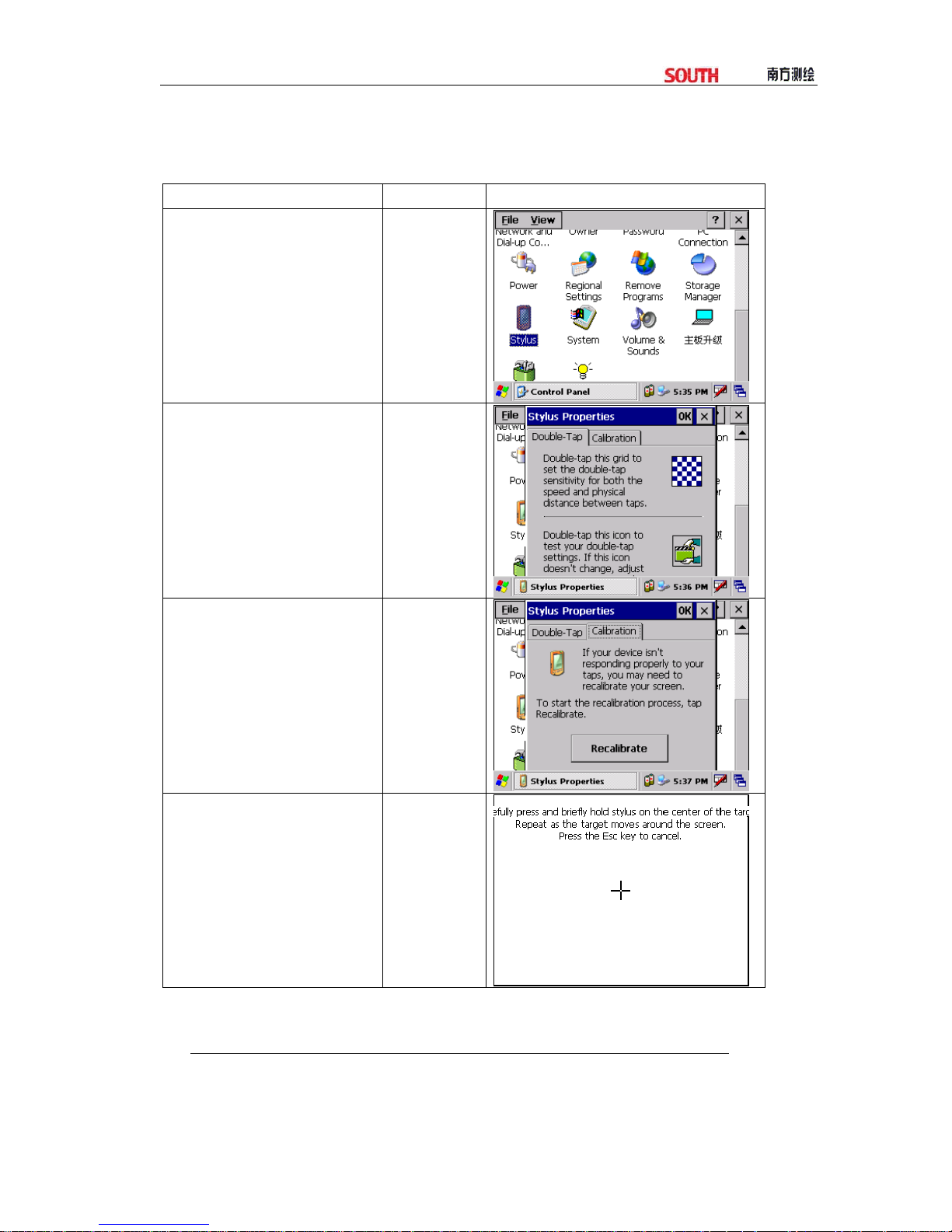
3.2.2 Touch-screenAdjustment
Ifthetouch‐screenisnotsensetothestylus,youneedtoadjustthetouch‐screen.
Howtoadjusttouch‐screen?
OPERATION STEPS KEY DISPLAY
①In “Control panel” find
“stylus” icon.
control panel
+
stylus
②Click “stylus”’
stylus
+
Calibration
③Click “Calibration”, and
then “Recalibrate”.
Calibration
+
Recalibrate
④According to the prompt,
use the stylus to click the cross
center. Repeat as the cross
moves around the screen.
Adjust 5 points as this.

12
⑤Press [ENT] to save new
setting,
Press [OK] to return to control
panel.
[ENT]
+
[OK]
3.3 APPROACHES TO INPUT NUMERALAND CHARACTER
ForTotalStationWinCE(R)Series,Twokindsofinputtingapproachesareavailable.
Oneisusingthekeyboard,likethekeyboardofamobilephone,with3characterson
onekey.Pressitoncetodisplaythefirstcharacters.Pressittwicetodisplaythe
secondone.Andpressitthreetimestodisplaythethirdone.Theotherapproachis
usingsoftkeyboard.Pressicon[ ]toenterinputtinginterface.Asanexample,here
wecreateafoldernamed“Job‐1”.
[Example 1:Inputting via soft keyboard]
OPERATIONAL STEPS KEY DISPLAY
①On desktop of WinCE,
press the blank area with
the stylus for a while.
②Select “New Folder” on
the pull-down menu appeared.

13
③On desktop of WinCE, a
new folder is created. And
activate the soft keyboard as
seen on the right. ※1)
④Click the [Shift] key on the
keyboard via the stylus to shift
to capital letter inputting
mode, as shown on the right.
Click letter [J] to input a
characters “J”.
[shift]
+
[J]
⑤The system automatically
returns to small letter inputting
mode. Use the stylus to click
characters key [o] and [b] to
input “o” and “b”.
[o]
[b]
⑥Click [-] to input “-”
[-]
Table of contents
Other South Measuring Instrument manuals

South
South Galaxy G2 User manual

South
South Galaxy G6 User manual

South
South Galaxy G1 User manual

South
South N6+ Series User manual

South
South N40 Series User manual

South
South N3 Series User manual

South
South N9 Series User manual

South
South N6 Series User manual

South
South GALAXY G7 User manual

South
South A1 Series User manual


Popular Measuring Instrument manuals by other brands


DT SWISS
DT SWISS PROLINE tensio 2 user manual

Cerlic
Cerlic CBX manual

Norav Medical
Norav Medical NR-1207-3 Installation and operation guide

Williams Sound
Williams Sound SoundPlus WIR TX850 Installation guide & user manual

Bosch
Bosch GLI 18V-1900 C Professional Original instructions

Leviton
Leviton VerifEye Series 4100 installation guide