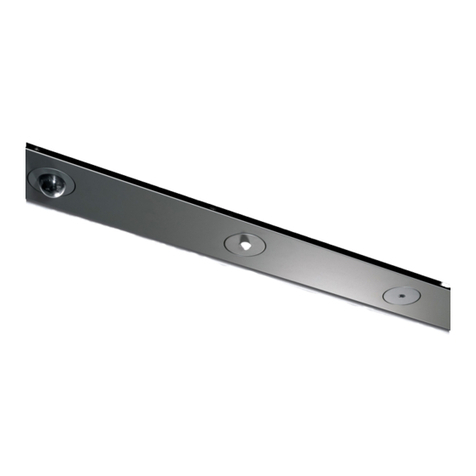
Price PARC Node User manual

Flush Channel Installation Guide

Flush Channel Installation Guide
1v001 | Flush Channel Installation Guide
NODE FLUSH CHANNEL INSTALLATION GUIDE
v001
© 2020 Price Industries Limited o/a PARC. All rights reserved.
TABLE OF CONTENTS
Product Overview.............................................................................................................................................................. 2
Read and Save These Instructions .................................................................................................................................... 3
Before You Start ................................................................................................................................................................ 3
Tools Required .................................................................................................................................................................. 3
Site Conditions, Storage and Handling Instructions ........................................................................................................... 3
Flush Channel Installation Sequence.................................................................................................................................. 4
Access Cables .................................................................................................................................................................. 4
Connecting Node Flush Channel Face to Mounting ........................................................................................................... 5
Connecting Node Flush Channels ..................................................................................................................................... 5
End Caps .......................................................................................................................................................................... 6
Cutting Node Flush Channels to Length ............................................................................................................................ 6
Node Device Installation .................................................................................................................................................... 6
Node Device Removal ....................................................................................................................................................... 7
Waste Disposal Management ............................................................................................................................................ 7

Flush Channel Installation Guide
2v001 | Flush Channel Installation Guide
Product Overview
The Node Flush Channel assembly consists of two mounting angles held together by intermittent mounting brackets,
which interface with the channel face.
The Node Flush Channel is designed to be installed between ceiling panels or plasterboard, in ceilings with recessed
voids.
The following guide should only be used for Node Flush Channel where PARC is not providing the diuser or plenum.
Please refer to our Node Flush Channel with Diuser Installation Guide if you are installing with the Node with Diuser.
It is recommended that the Node Flush Channel length is coordinated with the manufacturer to the required sizes to
match the building design. The Node Flush Channel can be site cut if required.
The Node devices are supplied separately from the channel assemblies.
Note: All mounting hardware and sub structure is to be supplied and installed alongside the Node Flush Channel.
Lighting and other services must be installed by qualified personnel.
For further information regarding product or installation, please contact info@parc-ceilings.com.
Figure 1
9.84
250
OVERALL WIDTH
3.57
91
CHANNEL HEIGHT
4.72
120
EXPOSED WIDTH
.23
6
RECOMMENDED CLEARANCE
W/ SURROUNDED CEILING
Flush Channel with Weave Panel
4.72
120
FACE WIDTH
.40
10 .12
3
RECOMMENDED CLEARANCE
W/ SURROUNDING CEILING
11.81
300
OVERALL WIDTH
4.16
106
CHANNEL HEIGHT
Flush Channel with Soft Cell Panel
Flush Channel with Weave Panel Flush Channel with Soft Cell Panel

Flush Channel Installation Guide
3v001 | Flush Channel Installation Guide
Read and save these instructions before beginning to install the Node Flush Channel.
Warning! To reduce the risk of re, electric shock, or injury to persons, observe the following:
• When cutting or drilling into wall or ceiling do not damage electrical wiring and other hidden utilities
• Use this unit only in the manner intended by the manufacturer. If you have any questions, contact the
manufacturer info@parc-celings.com.
Before You Start
Inspect all product parts for aws and shipping damage.
If anything is discovered to be damaged, contact the shipping company and manufacturer immediately.
Warning! Damaged or missing parts must be reported to PARC at [email protected]info@parc-ceilings.com immediately, PARC will
not be responsible for any damage or loss that occurs during unpacking or installation.
Site Conditions, Storage and Handling
Read this guide before handling the product.
• Read the Installation Guide before handling.
• Always wear appropriate hand protection when handling.
• Only store in clean dry conditions.
• Do not over stack.
• Do not stack in a way likely to cause falls.
Poor or rough handling, rolling or dropping of the product on corners or edges may cause damage to the product or
cause the product to deteriorate.
Lengths of Node should not span between points as any load applied mid-span may cause product damage.
Site storage of items should be at, preferably on a suitable pallet (supporting the entire length of the Node Flush
Channel) without additional top loading.
Consideration should be given to the advice of the Site Occupational Health and Safety Representative regarding
manual handling. An assessment should be made of any risk and if necessary mechanical lifting equipment should be
used.
The storage space must be cleared of debris and, in general, should be enclosed. The Node Flush Channel should be kept
clean, dry and protected from the elements.
Site conditions should be prepared for installation of the Node Flush Channel. The site should be clean, dry and clear of
other trades working in the ceiling void.
Flush Channel with Diffuser
Installation Guide
3
Flush Channel with Diffuser Installation Guide
Read and Save these Instructions before beginning to install Node Flush Channel with Diffuser:
Warning! To reduce the risk of fire, electric shock, or injury to persons, observe the following:
•When cutting or drilling into wall or ceiling do not damage electrical wiring and other hidden utilities.
•Use this unit only in the manner intended by the manufacturer. If you have any questions, contact the
manufacturer info@PARC-celings.com.
Before You Start:
Inspect all product parts for flaws and shipping damage.
If anything is discovered to be damaged, contact the shipping company and manufacturer immediately.
Node Flush Channel with Diffuser Installation Tools Required:
Site Conditions, Storage & Handling:
Read This Guide before handling the product.
•Read the Installation guide before handling.
•Always wear appropriate hand protection when handling.
•Only store in clean dry conditions
•Do not over stack.
•Do not stack in a way likely to cause falls.
Poor or rough handling, rolling or dropping of the product on corners or edges may cause damage to the product or
cause the product to deteriorate.
Lengths of node should not span between points as any load applied mid-span may cause product damage.
Site storage of items should be flat, preferably on a suitable pallet (supporting the entire length of the Node Flush
Channel with Diffuser) without additional top loading.
Consideration should be given to the advice of the Site Occupational Health & Safety Representative regarding manual
handling. An assessment should be made of any risk and if necessary mechanical lifting equipment should be used
Tools Required
LEVEL
4 MM HEX KEY
DRIVER T25 TORX DRIVER
5/16” / 8MM
SOCKET OR
WRENCH
LASER LEVEL MEASURING TAPE NODE REMOVAL
TOOL

Flush Channel Installation Guide
4v001 | Flush Channel Installation Guide
Flush Channel Installation Sequence
Before installing the Node Channel, ensure whenever possible, there is access to both sides.
The Node Flush Channel assembly consists of two mounting angles held together by intermittent mounting brackets
which interfaces with the Channel Face
Suspend the mounting angles and mounting brackets at the required level.
Fix suspension hangers to the mounting angles using the slots provided in the mounting angles.
It is recommended that the Node Flush Channel is supported no more than 150mm [6”] from an end or 150mm [6”]
from any joint.
Access Cables
Once the mounting assembly is installed, attached the Node access cables to the bridging plate in the mounting
assembly through the hole provided.
Before connecting the channel face to the mounting assembly, connect the other end of the Node access cable to the
ange on the inside of the channel face in the hole provided.
When lowering the channel onto access cable, the face should be lowered gently to avoid damage, ensuring that there
is no-one standing below.
Figure 2
Figure 3
Flush Channel with Soft Cell Panel
56.06
1424
118.11
3000
MAX LENGTH
118.11
3000
MAX LENGTH 35.43
900
MAX RECOMMENDED
SUPPORT SPACING
MOUNTING ANGLE
MOUNTING BRACKET
5.91
150 MOUNTING SLOT SPACING
10.63
270
MOUNTING WIDTH
MOUNTING ANGLE
Flush Channel with Soft Cell Panel
Flush Channel with Weave Panel
56.06
1424
118.11
3000
MAX LENGTH
118.11
3000
MAX LENGTH 35.43
900
MAX RECOMMENDED
SUPPORT SPACING
MOUNTING ANGLE
MOUNTING BRACKET
5.91
150 MOUNTING SLOT SPACING
10.63
270
MOUNTING WIDTH
MOUNTING ANGLE
Flush Channel with Soft Cell Panel
Flush Channel with Weave Panel
BRIDGING PLATE
ACCESS CABLES

Flush Channel Installation Guide
5v001 | Flush Channel Installation Guide
ALIGNMENT CLIP
(INSTALLED BY OTHERS)
FLUSH CHANNEL FACE
Connecting Node Flush Channel Face to Mounting
The Node Channel Face pushes onto the mounting brackets until you hear a click.
Connecting Node Flush Channels
Node Flush Channels can be connected together by way of plastic alignment clip. Alignment clips should be used to
ensure a high quality joint between adjacent channel faces.
Figure 4
Figure 6
Figure 5
Connect all required sections ensuring no visible gap between both sections.
Finished installation should be as shown below.
BRIDGE BRACKET
CHANNEL FACE
9.84
250
OVERALL WIDTH
3.57
91
CHANNEL HEIGHT
4.72
120
EXPOSED WIDTH
.23
6
RECOMMENDED CLEARANCE
W/ SURROUNDED CEILING
Flush Channel with Weave Panel
4.72
120
FACE WIDTH
.40
10 .12
3
RECOMMENDED CLEARANCE
W/ SURROUNDING CEILING
11.81
300
OVERALL WIDTH
4.16
106
CHANNEL HEIGHT
Flush Channel with Soft Cell Panel
Flush Channel with Weave Panel Flush Channel with Soft Cell

Flush Channel Installation Guide
6v001 | Flush Channel Installation Guide
End Caps
The Node Flush Channel can be provided with or without end caps as project design requirements. End caps are factory
installed as requested.
Cutting Node Flush Channels to Length
Where possible, the channel should be ordered to length based upon contractor site measurements.
Since end caps are factory installed and welded in place, cutting channels to length is not recommended where end
caps have been selected. If the channel must be cut to length, this should be done at the end, rather than a joint, to
minimize visual impact. The maximum length that can be trimmed is dened by the position of the bridge bracket.
Node Device Installation
Node devices can be integrated into the system at design stage and can be purchased separately from the Node
Channel.
Outer Node housings will be factory installed in the required locations.
The Node devices are installed in the housing by aligning the snap tabs and pushing the inner casing directly into the
housing.
Figure 8
Figure 7
INSERT NODE DEVICE INTO HOUSIN
G
OUTER NODE HOUSING
END CAP
Flush Channel with Soft Cell Panel
END CAP
Flush Channel with Weave Panel
Flush Channel with Weave Panel Flush Channel with Soft Cell

Flush Channel Installation Guide
7v001 | Flush Channel Installation Guide
The information contained in this document only provides guidance for the installation of PARC products. All PARC
products should only be installed by trained professionals and installation responsibility remains with the installer.
PARC reserves the right to review, alter, amend or remove publish data without notice as our policy is one of constant
improvement. The information contained in this installation guide is believed to be correct at the date of publication.
Whilst PARC will endeavor to keep its publications up to date, reader will appreciate that between publications there will
be changes in laws or other developments aecting the accuracy of the information contained in this installation guide.
Node Device Removal
To remove the Node device, insert the Node removal tool, supplied by PARC, into the shadow gap between the outer
housing and device. Slide the Node removal tool anti-clockwise until the Node device is released.
Figure 9
Waste Disposal Management
PARC Node Channels are shipped and packaged with protective material that should be disposed of in an appropriate
manner. Please remove or recycle waste and packaging materials as per your local waste disposal requirement.
DOWNLIGHT SPOTLIGHT LINEAR LIGHT
CAMERA BACNET MULTISENSOR DALI SENSOR
LUTRON SENSOR
EMERGENCY LIGHT PENDANT SPRINKLER
CONCEALED SPRINKLER
CHANNEL SPEAKER
A
ASECTION A-A
SIDE VIEW
4IN ROUND/OCT BOX
1.81
45.9
4.12
104.7
.23
5.9
3.54
90
CEILING CROSS SECTION
3.75
95.2
O
RECOMMENDED CUTOUT
.08
2
DEVICE FACE T O
UNFINISHED CEILING SURFACE
CEILING SURFACE
FLUSH CHANNEL
4.72
120
EXPOSED WIDTH
11.81
300
OVERALL WIDTH
4.33
110
CHANNEL HEIGHT
FLUSH CHANNEL WITH DIFFUSER
4.72
120
FACE WIDTH
.58
14.7
DIFFUSER OPENING
5.88
149.5
EXPOSED WIDTH
11.81
300
OVERALL WIDTH
4.33
110
CHANNEL HEIGHT
RECESSED CHANNEL W ITH DIFFUSER
4.72
120
RECOMMENDED
CEILING OPENING
11.81
300
OVERALL WIDTH
.08
2
CLEARANCE TO
DEVICE FACE
3.07
78
MOUNTING HEIGHT
FLUSH CHANNEL
FLUSH CHANNEL WITH DIFFUSER
RECESSED CHANNEL W ITH DIFFUSER
OPPOSED HORIZONTAL FLOW
VERTICAL FLOW
Other manuals for PARC Node
1
Table of contents
Other Price Security System manuals