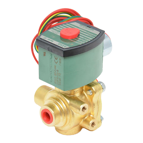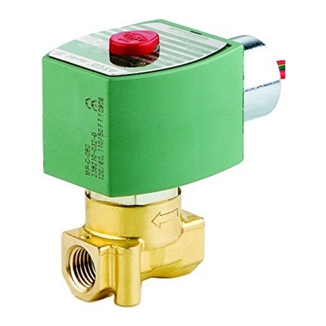
I&M No V7538
50 Hanover Road, Florham Park, New Jersey 07932 www ascovalve com
Page 2 of 3
Causes Of Improper Operation
Incorrect Pressure: C eck valve pressure. Pressure to valve must
be wit in range specified on nameplate.
Excessive Leakage: Disassemble valve and clean all parts. If parts
are worn or damaged, install a complete ASCO Rebuild Kit.
Valve Disassembly
1. Disassemble valve in an orderly fas ion using exploded views for
identification of parts.
2. Remove solenoid, see separate instructions.
3. If t e valve as a manual operator, refer to section on Manual
Operator Disassembly".
4. Unscrew solenoid base sub-assembly and remove core spring,
core assembly and body gasket.
5. A 4-40 mac ine screw provided in ASCO Rebuild Kit serves
as a self-tapping screw to remove insert from body. Turn screw
a few turns into t roug ole located in flat surface of t e insert.
C UTION: Do not damage center hole (pilot orifice) in raised
surface of insert. Remove insert by using a pair of pliers to grip
t e ead of t e screw.
6. Remove t ree gaskets from insert. Tag eac as t ey are
removed so t at t ey can be reassembled in t e same location.
Middle and lower gaskets ave t e same p ysical dimensions,
owever, t e lower gasket is a softer material. Remove disc
older sub-assembly and disc spring.
7. Remove end cap, end cap gasket and outer piston gasket.
8. Slide out piston assembly and inner piston gasket.
9. All parts are now accessible to clean or replace. Replace worn
or damaged parts wit a complete ASCO Rebuild Kit.
Valve Reassembly
1. Reassemble valve using exploded view for identification and
placement of parts.
2. Lubricate all gaskets wit DOW CORNING 111 Compound
lubricant or an equivalent ig -grade silicone grease.
3. Replace inner piston gasket and slide piston assembly into valve
body.
4. Replace outer piston gasket, end cap gasket and end cap
Torque end cap to 60"10 in-lbs. [6,8"1,1 Nm].
5. Position lower insert gasket and disc older spring
6. Snap upper and m,middle insert gaskets into grooves of insert.
Lower insert gasket fits into t e recess between t e lower
corner of t e insert and t e lower corner of t e body insert
cavity. Middle and lower insert gaskets are t e same size.
However, t e lower gasket is made of a softer material.
7. Place disc older assembly into insert. Install insert (wit gaskets
and disc older assembly) into body cavity, making certain t at t e
disc older spring is centered.
8. If t e valve being rebuilt as a manual operator, refer to section on
Manual Operator Reassembly."
9. Replace t e solenoid base gasket, core assembly wit spring.
10. Replace solenoid base sub-assembly (wit core assembly) into
valve body. Torque solenoid base sub-assembly to 175$25
in-lbs. [19,8$2,8 Nm].
11. Install solenoid, see separate instructions and make electrical
connections.
WARNING: o prevent the possibility of death,
serious injury or property damage, turn off electrical
power, depressurize solenoid operator and/or valve,
and vent fluid to a safe area before servicing.
12. Restore line pressure and electrical power supply to valve.
13. After maintenance is completed, operate t e valve a few times
to be sure of proper operation. A metallic click signifies t e
solenoid is operating.
Manual Operator Disassembly
WARNING: o prevent the possibility of death,
serious injury or property damage, turn off electrical
power, depressurize solenoid operator and/or valve,
and vent fluid to a safe area before servicing.
1. Remove retaining screws (2)
2. Slide out manual operator stem/knob/retainer sub-assembly.
3. Remove stem gasket, guide and guide gasket. Remove spring
(Suffix MS) only.
4. All manual operator parts are now accessible to clean or
replace. Replace worn or damaged parts wit a complete
ASCO Rebuild Kit.
Manual Operator Reassembly
1. Reassemble manual operator using exploded view for
identification and placement of parts.
2. Lubricate all gaskets wit DOW CORNING 111 Compound
lubricant or an equivalent ig -grade silicone grease.
3. Replace guide gasket, guide and stem gasket. Replace spring
(Suffix MS) wit small end on stem first.
4. Screw stem/knob/retainer into valve body using two retaining
screws. Torque retaining screws to 25"5 in-lbs. [2,8"0,6 Nm].
ORDERING INFORM TION
FOR SCO REBUILD KITS
Parts marked wit an asterisk (*) in t e exploded views are supplied
in Rebuild Kits. W en Ordering Rebuild Kits for ASCO valves,
order t e Rebuild Kit number stamped on t e valve nameplate. If t e
number of t e kit is not visible, order by indicating t e number of kits
required, and t e Catalog Number and Serial Number of t e valve(s)
for w ic t ey are intended.
