Grundfos MP 204 User manual
Other Grundfos Control Unit manuals

Grundfos
Grundfos CIM 260 User manual
Grundfos
Grundfos CIM 290-MA LPWAN GiC User manual
Grundfos
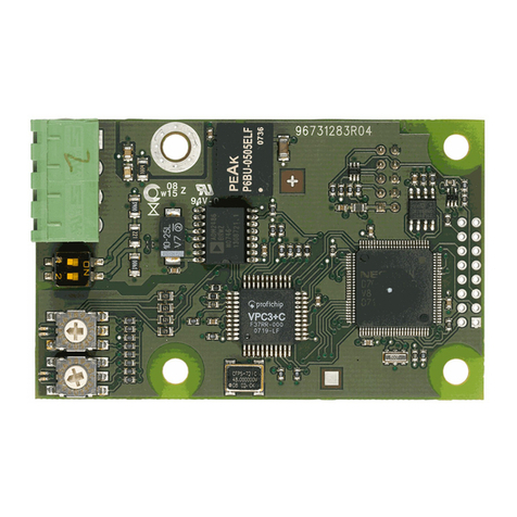
Grundfos SM 113 User manual
Grundfos
Grundfos CIM 150 User manual
Grundfos
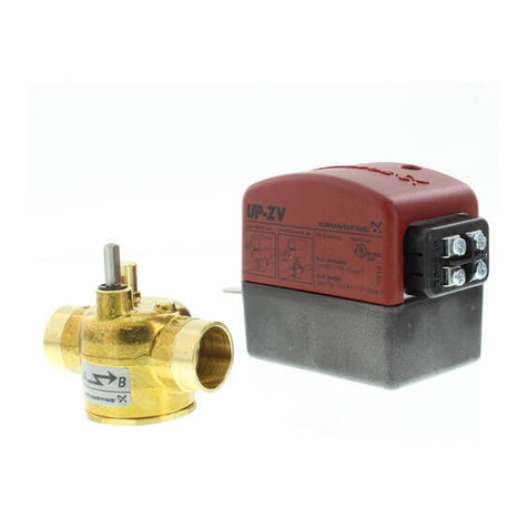
Grundfos CU 242 User manual
Grundfos
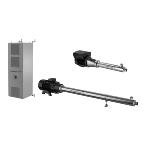
Grundfos UP-ZV Series Quick start guide
Grundfos
Grundfos BMS Series Operating instructions

Grundfos
Grundfos CIM 500 User manual
Grundfos
Grundfos CIU 251 User manual
Grundfos
Grundfos SA Series User manual
Grundfos
Grundfos MAGNA 2000 Series User manual
Grundfos
Grundfos CIM 200 User manual
Grundfos
Grundfos CIM 2 Series User manual
Grundfos
Grundfos OD 401 User manual
Grundfos
Grundfos PM 1 User manual
Grundfos
Grundfos CIM 100 User manual
Grundfos
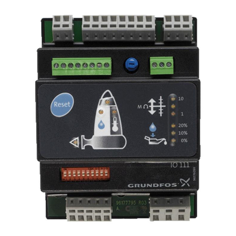
Grundfos IO 111 User manual
Grundfos
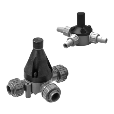
Grundfos PRV Series User manual
Grundfos
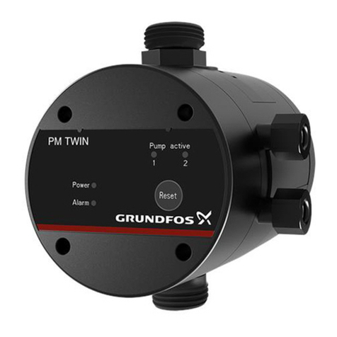
Grundfos PM TWIN User manual
Grundfos
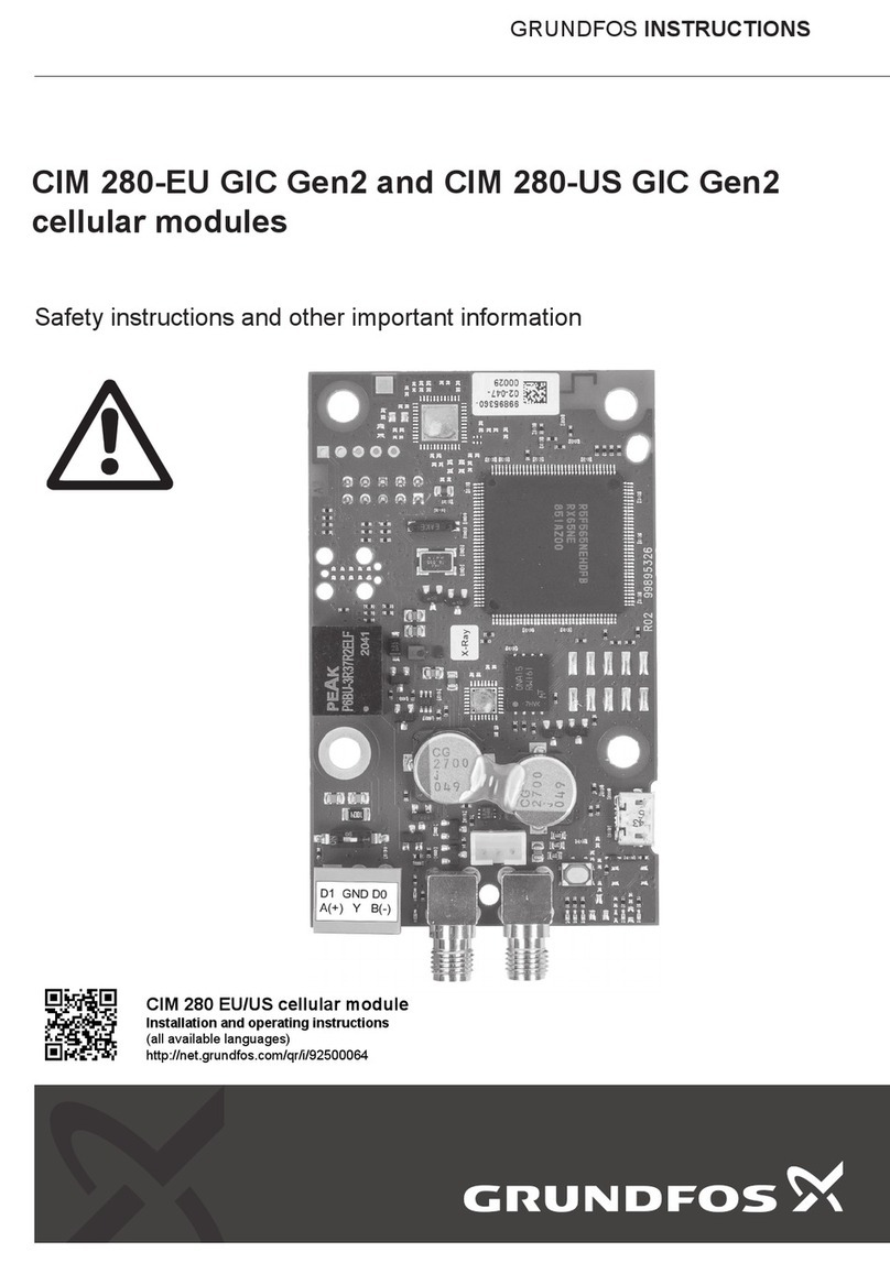
Grundfos CIM 280-EU GIC Gen2 User manual
Popular Control Unit manuals by other brands

Festo
Festo Compact Performance CP-FB6-E Brief description

Elo TouchSystems
Elo TouchSystems DMS-SA19P-EXTME Quick installation guide

JS Automation
JS Automation MPC3034A user manual

JAUDT
JAUDT SW GII 6406 Series Translation of the original operating instructions

Spektrum
Spektrum Air Module System manual

BOC Edwards
BOC Edwards Q Series instruction manual

KHADAS
KHADAS BT Magic quick start

Etherma
Etherma eNEXHO-IL Assembly and operating instructions

PMFoundations
PMFoundations Attenuverter Assembly guide

GEA
GEA VARIVENT Operating instruction

Walther Systemtechnik
Walther Systemtechnik VMS-05 Assembly instructions

Altronix
Altronix LINQ8PD Installation and programming manual
