Duemmegi Contatto Mod4TP/I User manual

Contatto
Mod4TP/I
Mod4TP/I: Module for controlling 4 roller
shutters or blinds with detection of travel
time and 8 digital inputs
Mod4TP/I module controls 4 independent 230Vac motors
with double winding for moving blinds roller shutters and
similar devices through the Contatto bus. The travel times
from the fully open to fully closed position and vice versa
are measured and stored automatically by detecting the in-
terruption of the current flow in the motors when the limits
are reached.
The measurement of the travel time allows extended fea-
tures of precise positioning of the roller shutter to any inter-
mediate value between 0 and 100% of the totally closed
position.
The output contacts for each motor feature an electrome-
chanic interlock in order to avoid damages to the motors
themselves and to the module.
Mod4TP/I module also provides 8 generic digital inputs for
connection of potential-free contacts (buttons switches or
other).
Main features of Mod4TP/I module are:
8 power contacts for controlling 4 roller shutters or
blinds
8 digital generic inputs of Contatto system
automatic measurement of the travel time for each mo-
tor
functions for full opening and closing and positioning to
any intermediate percentage value 0-100%
adjustment of the slats in the case of Venetian blinds
The module features removable terminal blocks for an easy
installation and maintenance. A 5-way terminal block is
dedicated to Contatto bus connection a 9-way terminal
block for connection of 8 inputs and 4 3-way terminal
blocks to connect the motors. A green LED next to the bus
terminal block reports the power on condition.
Mod4TP/I module is housed in a reduced height 6M modu-
lar box for DIN rail mounting.
Mod4TP/I module allows a high degree of configuration so
that it can be adapted to several operating conditions; the
configuration parameters will be detailed in the following
paragraphs.
Address programming
Mod4TP/I module takes inside the Contatto bus 1 input
and 1 output address each one made by 4 16-bit channels.
Assigning with the FXPRO programmer a base address n
the module is configured as In and On.
Wiring diagram
The following figure shows the wiring diagram for Mod4TP/I
module.
24V
BUS
0V
L1
L2
N
L1
L2
L3
PE
M
~M
~M
~M
~
Power supply 24V=
25% / 95mA
+24V
0V
L1
L2
P
114 16 1715
Contatto
DUEMMEGI
MILANO-ITALY
2 3 4 5 6 7 8
13
ADDRESS
MOD4TP/I
Shutter module
C
A1 A2 A3 B1 B2 B3 C1 C2 C3 D1 D2 D3
L L L L
ON
IN
The wiring of the motors to different phases is allowed.
DUEMMEGI s.r.l. - Via Longhena 4 - 20139 MILANO
Tel. 02/57300377 - Fax 02/55213686 – www.duemmegi.it
Rel.: 1.0 June 2016 Page 1 of 6

Contatto
Mod4TP/I
Information form and to Mod4TP
Mod4TP/I module as said above takes an input and an
output address 4-channel 16-bit; the following tables list
the information mapped on these addresses:
Input section:
IN
Point CH1 CH2 CH3 CH4
1
Shutter/Slats position 1
Shutter/Slats position 2
Shutter/Slats position 3
Shutter/Slats position 4
2
3
4
5
6
7
8
9IN1 IN3 IN5 IN7
10 IN2 IN4 IN6 IN8
11 ----
12 ----
13 MOT1 Up MOT2 Up MOT3 Up MOT4 Up
14 MOT1 Dw MOT2 Dw MOT3 Dw MOT4 Dw
15 MOT1 ON MOT2 ON MOT3 ON MOT4 ON
16 CAL. 1 CAL. 2 CAL. 3 CAL. 4
Shutter/Slats position n: the 8 least significant bits of
each channel report as a number between 0 and 100 the
position of the roller shutter or the position of the slats posi-
tion depending on the last selection made by the command
0x20 (see output section that follows). The position 0 is ful-
ly open 100 is fully closed.
IN1..IN8: the points 9 and 10 of each channel report the
status of the related input 1..8 of the module.
MOTn Up, MOTn Dw: points 13 and 14 of each channel
will be activated when the related motor is running in for
opening or closing respectively; these points allow to report
the motors status.
MOTn ON: point 15 of each channel will be activated when
the related motor is running; this point allows to show if a
motor is currently driven or not (in practice it is the logic
sum of point 13 and 14 described before).
CAL. n: point 16 of each channel will be activated when the
calibration of the related shutter is running (detection of the
travel time).
Output section:
OUT
Point CH1 CH2 CH3 CH4
1
Value 1
Value 2
Value 3
Value 4
2
3
4
5
6
7
8
9
Command 1
Command 2
Command 3
Command 4
10
11
12
13
14
15
16
The 4 output channels allow to send several commands
and settings to the module.
The executed function depends on the Command code and
on the Value as described in the following table (in hexa-
decimal format).
Com. Val. Function
0x00
0x00 NOP (no operation)
0x01 Open
0x02 Close
0x04 Open after a programmed delay
0x08 Close after a programmed delay
0x10 Stop
0x11 Open for 1 step time
0x12 Close for 1 step time
0x01 P Move shutter to position P (0..00%)
0x02 P Move slats to position P (0..100%)
0x11 T Set opening/closing delay to T (0-255s) (1)
0x12 T Set opening/closing timeout to T (0-255s) (1)
0x13 T Set opening time to T (0.00-240.00s) (2)
0x14 T Set closing time to T (0.00-240.00s) (2)
0x15 N Set number of step N (0-255) for slats (3)
0x16 T Set step time T for slats (0.00-2.55s) (3)
0x17 T Set pause time (0.0-25.5s) (4)
0x18 N Slats dead time at 0% in step number (0-255) (5)
0x19 N Slats dead time at 100% in step num. (0-255) (5)
0x20
0x00 Disable automatic function (6)
0x01 Enable automatic function (6)
0x02 Set short push for automatic (7)
0x03 Set long push for automatic (7)
0x04 Report shutter position on input CH (8)
0x05 Report slats position on input CH (8)
0x06 Set shutter mode (no slats) (9)
0x07 Set blind mode (with slats) (9)
0xAA 0x55 Execute calibration (10)
The commands for parameter settings (Com. 0x11 to 0x20)
are useful for a supervisor; normally the module has to be
set using the related configuration panel in MCP Ide pro-
gram (see the related paragraph).
DUEMMEGI s.r.l. - Via Longhena 4 - 20139 MILANO
Tel. 02/57300377 - Fax 02/55213686 – www.duemmegi.it
Rel.: 1.0 June 2016 Page 2 of 6

Contatto
Mod4TP/I
(1): steps of 1s; when sending to module a command
0x0004 or 0x0008 the start of the motor will be delayed by
this value
(2): steps of 0.01s; T must be the desired time in s multi-
plied by 100 and it is the time which the shutter takes to go
from one extreme to another. Normally these times are
measured by the module itself; they may be entered manu-
ally in cases where the motor of the shutter does not allow
the detection of the travel time.
(3): slats adjustment takes place by driving the motor for a
fairly short time (step): the lower this time and the better the
resolution in the positioning. Once the time step has been
set the motor must be repeatedly driven starting from
completely closed slats and counting how many steps are
needed to fully open the slats. The following paragraphs
will give more information on setting these parameters. The
step time can be set in steps of 0.01s therefore the T pa-
rameter in the table must be the desired time in s multiplied
by 100.
(4): steps of 0.1s; T must be the desired time multiplied by
10. This is the pause time before a reversal of the motor di-
rection.
(5): these parameters are used to compensate the dead
times of the slats mechanism. See the section about con-
figuration for more information.
(6): enables and disables the automatic operation.
(7): the full opening or closing of the shutter can be per-
formed as the result of a short or long push on the related
control button. These codes allow to choose the preferred
mode; in the case of blinds with slats always choose “long
push for automatic”.
(8): each one of the 4 input channels can report the posi-
tion of the roller shutter or the one of the slats (as a value
between 0 and 100). To choose which of the two parame-
ters must be inserted into the input channel use these
codes (0x2004 and 0x2005)
(9): these codes allow you to choose between roller shutter
mode (without slats) or blind mode (with slats).
(10): This code begins the process for the detection of the
travel times. See the following paragraphs for more infor-
mation about this subject.
Installation and setting up
The advanced functions of Mod4TP/I module require to set
during startup the parameters necessary for the proper op-
eration of the shutter.
The configuration is performed via bus using the specific
tool in MCP Ide. Select from MCP Ide menu Program-
ming Modules Configuration MOD4TP; the window in Fig-
ure 1 will appear showing the usual buttons for reading
programming and ID/FW version request of the module
which address is equal to that entered into the related field.
The values reported in the configuration panel for each of
each one of the 4 motors have the following meaning:
DUEMMEGI s.r.l. - Via Longhena 4 - 20139 MILANO
Tel. 02/57300377 - Fax 02/55213686 – www.duemmegi.it
Rel.: 1.0 June 2016 Page 3 of 6
Figure 1

Contatto
Mod4TP/I
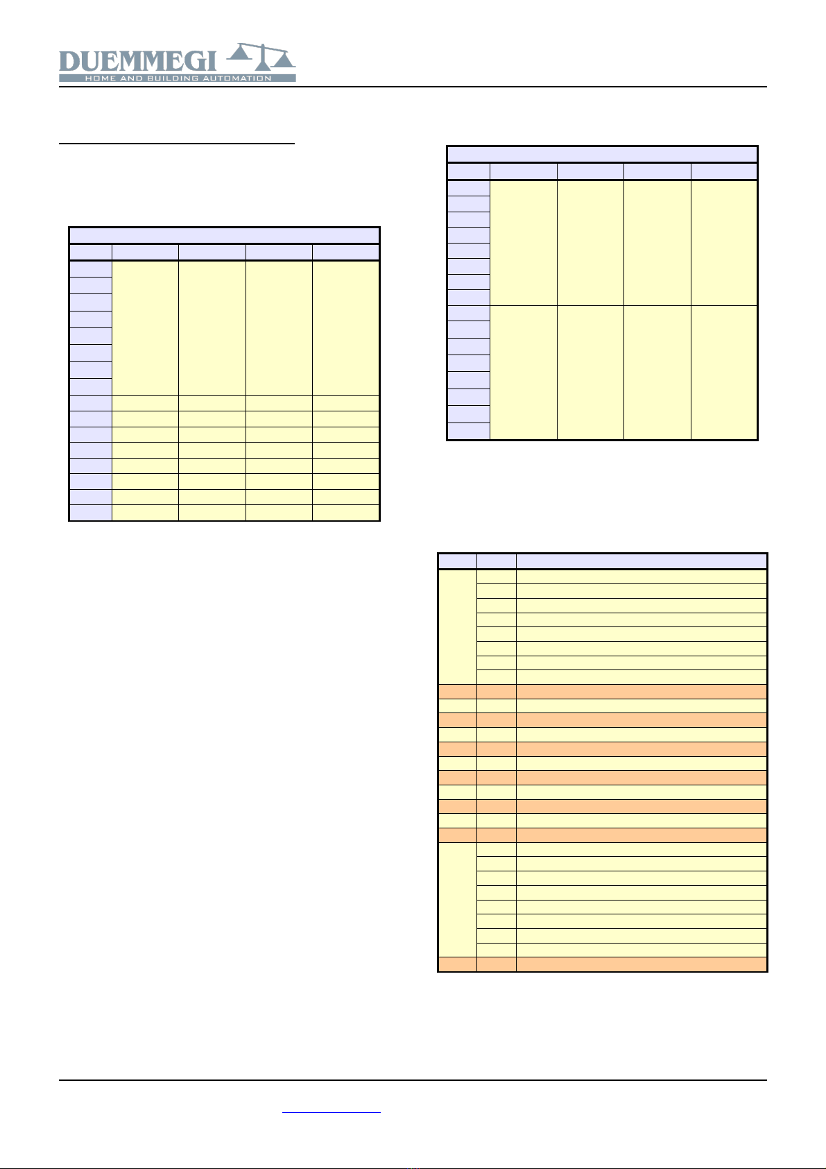
T Open: is the time the roller shutter needs to go from the
fully closed to the fully opened position; this time is mea-
sured by the module itself during the calibration procedure
but it can also be manually entered (eg. if the used motor
does not allow the detection of the travel time or to copy
the value from another identical shutter already calibrated)
T Close: is the time the roller shutter needs to go from the
fully opened to the fully closed position; this time is mea-
sured by the module itself during the calibration procedure
but it can also be manually entered (eg. if the used motor
does not allow the detection of the travel time or to copy
the value from another identical shutter already calibrated)
Timeout: maximum time during which the motor is driven
(it must be greater eg. of about ten seconds than the pre-
vious two times); this time too in case of calibration is cal-
culated by the module itself
T Step: is the duration of the driving step (pulse) to the mo-
tor to move the slats; lower this time and the higher the res-
olution in the positioning of the slats (min. 0.01s); a typical
step T Step = 0.05s is suggested
N Step: is the number of steps required to perform a com-
plete movement of the slats
Delay: when sending commands 0x0004 or 0x0008 to the
module the start of the motor is delayed by this value
Pause: the motor stopping time before reversing the move-
ment; follow the specifications of the manufacturer of the
roller shutter
DTSxC: is the dead time expressed as number of steps of
duration T Step each one needed by the slats starting
from the fully opened position to begin to rotate
DTSxO: is the dead time expressed as number of steps of
duration T Step each one needed by the slats starting
from the fully closed position to begin to rotate
DTSh: is the dead time in seconds needed by the shutter
to begin to open when starting from the fully closed position
After making sure that the module has been addressed and
connected to the motors correctly follow the following pro-
cedures depending on whether it is a roller shutter with
slats or not.
Rolling shutter with slats
enter in the Mod4TP configuration window the module
address
execute a reading of the current parameters (Read);
this is necessary in the case some motors have al-
ready been set and thus their configuration must not
be corrupted
select for the desired motor the options Slats=Yes
Auto=Yes PressxAuto=Long Pos.onBus=Shutter
enter for the desired motor T.Step = 0.05s DTSxO =
0 and DTSxC = 0
execute a writing (Program) in order to transfer the en-
tered parameters
move the shutter to a height such that the slats move-
ment can be seen and easily evaluated (use the map
in MCP Ide)
move the shutter until the slats are fully closed (usually
by sending a Close command)
perform a series of opening steps and count the num-
ber of steps required to actually start the movement of
the slats; this number of steps is the parameter DTSx
O (mechanical dead time as number of steps starting
from slats closed). Enter this value in the related text
box of configuration panel
move the shutter until the slats are fully open (usually
by sending an Open command)
perform a series of closing steps and count the num-
ber of steps required to actually start the movement of
the slats; this number of steps is the parameter DTSx
C (mechanical dead time as number of steps starting
from slats opened). Enter this value in the related text
box of configuration panel
execute a writing of the module (Program) in order to
transfer the two newly entered values
move again the shutter until the slats are fully closed
(usually by sending a Close command)
perform one opening step: the motor should be driven
for the time necessary to recover the mechanical dead
time
perform a series of opening steps and count the num-
ber of steps required to move the slats in the com-
pletely opened position; This number of steps is the
parameter N.Step (number of steps required to per-
form a complete movement of the slats). Enter this val-
ue in the related text box of configuration panel
execute a writing of the module (Program) in order to
transfer the parameter just entered
at this point it is possible to perform an automatic cali-
bration that is the measurement of the opening and
closing times; to do this press the button Calib. related
to the desired motor in the configuration window then
wait for the completion of the operation (for details on
the calibration procedure see the related paragraph)
at the end of calibration perform a reading (Read); the
3 parameters T Open T Close. and Timeout in the
configuration window should contain the measured val-
ues for that shutter
complete the parameter setting by entering the desired
values for Delay and Pause (for the latter parameter
the value 0.5s generally goes well)
Rolling shutter without slats
enter in the Mod4TP configuration window the module
address
execute a reading of the current parameters (Read);
this is necessary in the case some motors have al-
ready been set and thus their configuration must not
be corrupted
select for the desired motor the options Slats=No
Auto=Yes PressxAuto=Short Pos.onBus=Shutter
execute a writing (Program) in order to transfer the en-
tered parameters
perform an automatic calibration that is the measure-
ment of the opening and closing times; to do this
press the button Calib. related to the desired motor in
the configuration window then wait for the completion
of the operation (for details on the calibration proce-
dure see the related paragraph)
DUEMMEGI s.r.l. - Via Longhena 4 - 20139 MILANO
Tel. 02/57300377 - Fax 02/55213686 – www.duemmegi.it
Rel.: 1.0 June 2016 Page 4 of 6

Contatto
Mod4TP/I
at the end of calibration perform a reading (Read); the
3 parameters T Open T Close. and Timeout in the
configuration window should contain the measured val-
ues for that shutter
complete the parameter setting by entering the desired
values for Delay and Pause (for the latter parameter
the value 0.5s generally goes well)
Calibration
To move the roller shutter or the venetian blind to a desired
position the module drives the motor for a well defined
time; this technique requires accurate measurement of
travel times from fully open to fully closed position and vice
versa. These two times are measured by the module itself
during the calibration procedure that consists in the follow-
ing steps:
full opening of the shutter (until upper limit stop end)
fully closing (until lower limit end) and measuring the
time needed to go from one extreme to the other one
storage of the closing time
complete opening (until upper limit end) and measur-
ing the time needed to go from one extreme to the oth-
er one
storage of the opening time
MCP XT and MCP 4 programming
Like for any Contatto module each Mod4TP/I module in-
stalled in the plant must be declared in the MCP program.
Therefore in the MCP Ide Configuration tab a directive
similar to the following one must be entered for each Mod-
4TP/I module:
MOD4TP = ( Ix, Ox )
where x is the address assigned to the module.
To send commands to a channel of Mod4TP/I module from
bus input points (real or virtual) an equation similar to the
following one must be used:
AO1:1 = P(0x0001)I14.1 & P(0x0000)!I14.1 & \
P(0x0002)I14.2 & P(0x0000)!I14.2 & \
P(0x0132)I14.3 & P(0x014B)I14.4
where I14.1 and I14.2 are Open and Close commands
(see the table listing the bus commands).
The two terms !I14.1 and !I14.2 cause the sending of
the NOP code (no operation) at the releasing of the related
pushbuttons; these terms are very important because they
allow to the module to measure the pushing time of the but-
ton and in order to decide to perform a manual or automatic
movement. The information about the releasing is needed
only for the commands Open and Close Open and close
after delay and Open and Close for a step.
If two or more roller shutters have been driven in the same
way it is possible to load the related commands in a regis-
ter and then copy the register to the desired shutter chan-
nels as follows:
R0 = P(0x0001)I14.1 & P(0x0000)!I14.1 & \
P(0x0002)I14.2 & P(0x0000)!I14.2 & \
P(0x0132)I14.3 & P(0x014B)I14.4
AO1:1 = R0
AO1:2 = R0
AO1:3 = R0
AO1:4 = R0
A supervisor can send commands to the shutter channels
by writing the command code and value directly to the out-
puts or in the case of the example showing the use of the
register by writing directly to the register itself.
Mapping
MCP Visio allows to show Mod4TP/I module as in Figure 2.
As for all other Contatto modules the background is in
green color if the module is connected and properly work-
ing otherwise the background is in red color. The status of
digital input points is shown on the map in red or green col-
or depending on the status ON or OFF respectively. The 4
white text boxes under digital input points report the current
position of the 4 shutters.
DUEMMEGI s.r.l. - Via Longhena 4 - 20139 MILANO
Tel. 02/57300377 - Fax 02/55213686 – www.duemmegi.it
Rel.: 1.0 June 2016 Page 5 of 6
Figure 2

Contatto
Mod4TP/I
The 4 pairs of Command/Value text boxes allow to send
commands/values to the 4 channels (such as listed in the
the related table).
The four groups of three buttons send Open Stop and
Close commands respectively (with the related handling of
the long/short pressure). The 4 pairs of buttons + and - fi-
nally allow to control the slats executing one step for each
press of the related button.
Technical characteristics
Supply voltage 24V ± 25% SELV
MAX current consumption 95mA @ 24V
Relays contact:
Rating for res. load
1-phase motor
MAX peak current
5A @ 250V~
2.4A @ 250V~ (550VA 0 75HP)
150A (20ms)
Min motor current for travel
time detection
> 100mA
Number of digital inputs 8 for potential free contacts
Nominal input voltage on
digital inputs
24V
Current for each digital input 4mA @ 24V
Operating temperature -10 ¸ +50 °C
Storage temperature -30 ¸ +85 °C
Protection degree IP20
Outline dimensions
90mm
58mm
106mm
Power supply 24V= 25% / 95mA
+24V
0V
L1
L2
P
114 16 1715
Contatto
DUEMMEGI
MILANO-ITALY
234567813
ADDRESS
MOD4TP/I
Shutter module
C
A1 A2 A3 B1 B2 B3 C1 C2 C3 D1 D2 D3
L L L L
ON
IN
Installation and use restrictions
Standards and regulations
The design and the setting up of electrical systems must be per-
formed according to the relevant standards guidelines specifica-
tions and regulations of the relevant country. The installation
configuration and programming of the devices must be carried out
by trained personnel.
The installation and the wiring of the Contatto bus line and the re-
lated devices must be performed according to the recommenda-
tions of the manufacturers (reported on the specific data sheet of
the product) and according to the applicable standards.
All the relevant safety regulations e.g. accident prevention regula-
tions law on technical work equipment must also be observed.
Safety instructions
Protect the unit against moisture dirt and any kind of damage dur-
ing transport storage and operation.
Do not operate the unit outside the specified technical data.
Never open the housing. If not otherwise specified install in closed
housing (e.g. distribution cabinet).
Earth the unit at the terminals provided if existing for this purpose.
Do not obstruct cooling of the units.
Setting up
The physical address must be assigned with the specific program-
mer and the setting of parameters (if any) must be performed by
the specific configuration softwares; for more details refer to the
specific data sheet of the product. For the first installation of the
device generally and unless otherwise specified on the specific
data sheet of the product proceed according to the following
guidelines:
Check that any voltage supplying the plant has been removed
Assign the address to module (if any)
Install and wire the device according to the schematic dia-
grams on the specific data sheet of the product
Only then switch on the 230Vac supplying the bus power sup-
ply and the other related circuits
Applied standards
The devices belonging to Contatto line comply with the essential
requirements of the following directives:
2014/30/UE (EMC)
2014/35/UE (Low Voltage)
2011/65/UE (RoHS)
Correct disposal of the product (waste electrical & electronic
equipment)
(Applicable in the European Union and other Euro-
pean countries with separate collection systems).
This marking on the product accessories or docu-
mentation indicates that the product and its electron-
ic accessories should not be disposed of with other
household waste at the end of their working life. To
prevent possible harm to the environment or human health from
uncontrolled waste disposal please separate these items from oth-
er types of waste and recycle them responsibly to promote the
sustainable reuse of material resources. Household users should
contact either the retailer where they purchased this product or
their local government office for details of where and how they can
take these items for environmentally safe recycling. Business
users should contact their supplier and check the terms and condi-
tions of the purchase contract. Adequate disposal of the decom-
missioned equipment for recycling treatment and environmentally
compatible disposal contributes in preventing potentially negative
effects on the environment and health and promotes the reuse
and/or recycling of equipment materials. Abusive product disposal
by the user is punishable by law with administrative sanctions.
DUEMMEGI s.r.l. - Via Longhena 4 - 20139 MILANO
Tel. 02/57300377 - Fax 02/55213686 – www.duemmegi.it
Rel.: 1.0 June 2016 Page 6 of 6
Table of contents
Popular Window Blind manuals by other brands

Dometic
Dometic SKYSOL 2 manual

YewdaleDefiant
YewdaleDefiant VL31 Split Draw Manufacturing Instructions

CHILD SAFETY
CHILD SAFETY arzion outdoor Mounting instruction

Sundrape
Sundrape Star Elektra instructions

Style selections
Style selections 978840204 Assembly instructions

Kirsch
Kirsch Alternative Wood Blinds Series installation instructions

Velux
Velux RMM Important information

Barnes
Barnes PERFECT FIT Fitting instructions

ConceptBlindsDirect
ConceptBlindsDirect Aquarius operating instructions

Victoria M
Victoria M SYSTEM VS 1 Original assembly instructions

POWERSHADES
POWERSHADES SQUARE CASSETTE installation guide

IKEA
IKEA FYRTUR E1753-60 manual