manuals.online logo
Brands
  1. Home
  2. •
  3. Brands
  4. •
  5. Duevi
  6. •
  7. Security Sensor
  8. •
  9. Duevi DDT-2 Guide

Duevi DDT-2 Guide

Terminals
AC/AC Anti-masking output N.C.
TM/TM Anti-opening tamper output + bracket anti-removal (in series) N.C.
AL/AL Alarm output N.C.
AB Microwave enabling input.
Apply a positive 9 ÷ 15 VDC voltage to switch o the microwave but
maintain the infrared active (the alarm AL/AL output signals the
detection of infrared element)
- Power supply negative reference
+Power supply positive reference (nominal: 12 VDC)
Wired Dual Technology Detector
Installation and use manual 2021.09-M:1.1-H:SE-03v4-13-F:1.0
DESCRIPTION
Thank you for choosing our dual technology detector for your security system.
DDT-2 is a compact dual-technology movement detector equipped with passive
infrared (PIR) and microwave (MW) detection elements. When both
technologies detect movement or at masking attempts (AM), the alarm starts.
This detector assure to your security system an high-level protection reliability
against intruders and nuisance.
FEATURES
• Detector range: about 12 m
• Microprocessor-based signal analysis
• Anti-masking (AM)
• LEDs dedicated to dierent detections: microwave, infrared, alarm
• Memory and display of anti-masking event
• Memory and display of alarm event
• Anti-tampering protection (Tamper)
• Input for microwave enabling
• 100 Hz neon lights lter
• Low absorption, max 7 mA
• Microwave sensitivity ne adjustment
• Immune to intense electro-magnetic elds
TECHNICAL *
* Specications can vary without notice
Power supply 9 ÷ 15 VDC (nominal: 12 VDC)
Absorption Max: 7 mA @ 12 V (LED o)
Microwave
Pulsed microwave, patch-array type
Working frequency: 24,125 GHz
Excluded by AB input
Infrared Double element passive infrared
Alarm/Anti-mask timing 2 seconds
Outputs:
Alarm
Tamper
Anti-mask
OptoMOS (solid state relay) N.C. **
max 50 VDC / 100 mA
contact impedance: 7 ÷ 16 Ω
** Outputs open in case of power loss
Detection range Min: 2 m - Max: 12 m, 104° @ 25 °C
Installation height 2.3 m (typical)
Speed detection range 0.3 ÷ 3.0 m/s
RFI immunity Mean: 10 V/m
Temperature -20 °C ÷ 50 °C
Humidity 95 % (relative) max
Dimension 112 x 66 x 46 mm
Weight About 90 g
INSTALLATION TIPS
Do not install the detector exposed to direct or
reected sunlight, or towards windows facing
streets (to avoid car ash lightings).
Verify that there are not obstacles (trees, shields,
furniture, etc.) within the detection area, which
can cause masking / false detections.
Avoid to install the sensor faced towards heating
systems and/or conditioning systems causing fast
temperature variations.
Place the sensor at least at 1 meter far from the
nearest uorescent light source to avoid
interference with the microwave element.
DESCRIPTION
Bracket tamper Terminals
MW status LED IR status LED
DIP-SWITCH
DIP1:LED
DIP2:ANTIMASK
MW sensitivity
Infrared
DDT-2
Cover tamper
Microwave
Range adjustment:
• “0” = 12m
• “-3” = 12m +20%
• “+3” = 12m - 20%
Disabling jumper:
J.TCO (cover)
J.TBR (bracket)
Alarm
status LED
JUMPERS
JUMPERS ON OFF
J.TCO (Cover tamper) Tamper disabled Tamper enabled
J.TBR (Bracket tamper) Tamper disabled Tamper enabled
DIP-SWITCH
DIP ON OFF
DIP1 (LED) LED enabled LED disabled
DIP2 (ANTI-MASKING) ANTI-MASK enabled ANTI-MASK disabled
GREEN LED ALARM EVENTRED LED
ON AlarmON
ON Alarm + Anti-maskingBLINKING
OFF Anti-maskingBLINKING
ALARM MEMORY
When the AB terminal is at 9 ÷ 15 VDC (microwave disabled) it is possible to
visualize the EVENTS LOG.
The alarm memory shows the last alarm type (detection or anti-mask) occurred
from last time the AB terminal switched from rest to positive voltage.
At rst IR detection (after the AB terminal switched to positive and then alarm)
the LEDs light on for one minute according to next table:
The memory log does not store events occurred in the 30 seconds before the
switching of AB to positive (entry time). The same, no memory log of events
occurred in the 30 seconds after the switching of AB to rest (exit time).
The alarm memory is displayed even if LEDs are disabled (DIP1 = OFF).
DETECTION TEST
It is necessary to make a crossing test (walk test) of the detection area of the
sensor to verify a correct covering. The test also shows if both technologies (PIR
and MW) work on the same area.
1. Power up the sensor and wait about 45 seconds until it is ready.
2. Set DIP1 = ON (LED enabled).
3. Walk normally crossing the detection area.
The red IR LED lights on at PIR detection, the green MW LED lights on at
MW detection, the blue AL LED lights on when both technologies detect
movement.
4. If the microwave sensitivity is too high (the green LED lights on at minimum
movement), adjust it turning the trimmer TR.MW counter-clockwise (to
decrease the sensitivity).
MICROWAVE SENSITIVITY
TRIMMER TR.MW MIN
(trimmer counter-clockwise)
MAX
(trimmer clockwise)
Range 2 m 12 m
LED *
LED MW GREEN Microwave MW detection
LED IR RED Infrared IR detection
LED AL BLUE Alarm: MW+IR detection, anti-masking
* When AB input is at 9 ÷ 15 VDC the LEDs show alarm memory (see “Alarm
Memory” paragraph)
MICROWAVE DISABLING
The AB input - when at 9 ÷ 15 VDC - switches o the microwave.
This function allows to avoid microwave irradiation reducing the
electromagnetic pollution.
NOTE: when the MW element is disabled, the infrared continues to detect,
changing the AL/AL output status. If is necessary to completely bypass the
sensor, the AL/AL terminals must be connected to a control panel zone
properly programmed.
DETECTION AREA
Dimension: 104° - radius12 m (at 25 °C)
Top view
2,0 m
2,3 m
4,4 m 12,0 m
0 m 104 °
Side view
RANGE ADJUSTMENT (POSITIONS +3 / 0 / -3)
Depending on the position the electronic board is xed to the frame, the max
range of the sensor vary of about ± 20% (@ 25 °C):
“0”
12 m
“+3”
12 m +20% (~14 m)
“-3”
12 m -20% (~10 m)
INSTALLATION AND CONNECTION
1. Mount the base of the bracket in wanted position. Pass the cables into the
apposite holes of the bracket.
2. Open the cover of the sensor and gently remove the PCB from the frame.
Pass the cables inside the frame and mount it on the bracket (as shown in
next gure).
3. Connect the cables to the proper terminals. Place the PCB back on the
frame. Close the cover and make some detection tests.

Other Duevi Security Sensor manuals

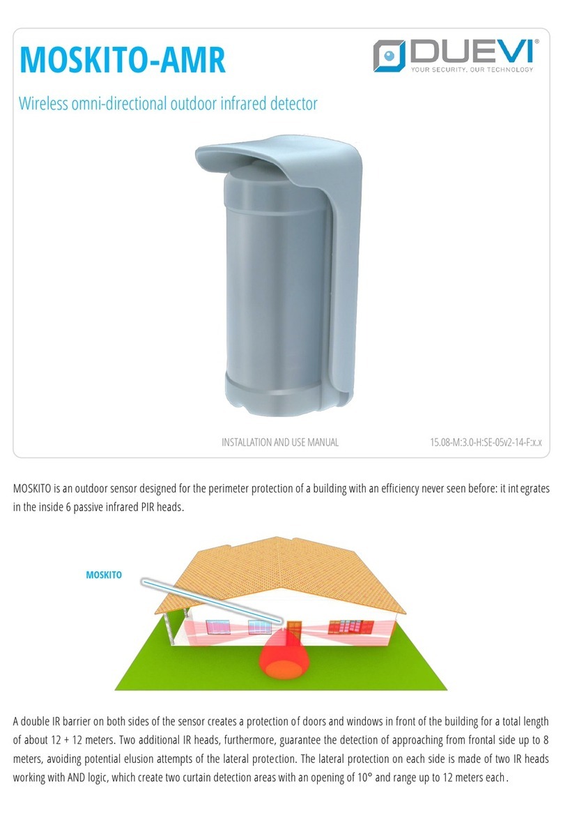
Duevi MOSKITO-AMR Guide

Duevi

Duevi MOSKITO-AMR Guide

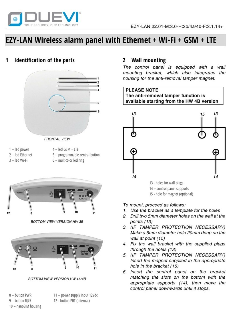
Duevi EZY-LAN User manual

Duevi

Duevi EZY-LAN User manual

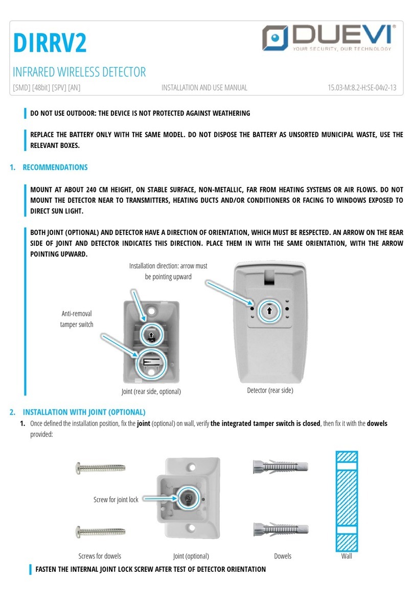
Duevi DIRRV2 Guide

Duevi

Duevi DIRRV2 Guide

Duevi SIRPZ-RB-868 Instruction Manual

Duevi

Duevi SIRPZ-RB-868 Instruction Manual

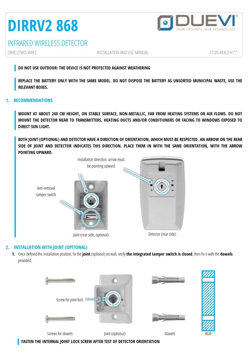
Duevi DIRRV2 868 Guide

Duevi

Duevi DIRRV2 868 Guide

Popular Security Sensor manuals by other brands

Sierra RED1-HST installation manual

Sierra

Sierra RED1-HST installation manual

Level Sense Pro user manual

Level Sense

Level Sense Pro user manual

Novar ED&S Wireless Passive Infra-Red Movement Detector Installation and operating instructions

Novar ED&S

Novar ED&S Wireless Passive Infra-Red Movement Detector Installation and operating instructions

ELRO HA2000PP instruction manual

ELRO

ELRO HA2000PP instruction manual

CRX IKH6014 instruction manual

CRX

CRX IKH6014 instruction manual

Satel COBALT Pro user manual

Satel

Satel COBALT Pro user manual

PCB Piezotronics 4105-02A Installation and operating manual

PCB Piezotronics

PCB Piezotronics 4105-02A Installation and operating manual

Visonic FLD-550 PG2 installation instructions

Visonic

Visonic FLD-550 PG2 installation instructions

SkyLink HA-434 quick start guide

SkyLink

SkyLink HA-434 quick start guide

Data Harvest 1130 manual

Data Harvest

Data Harvest 1130 manual

Analytical Technology PortaSens III D16 instruction manual

Analytical Technology

Analytical Technology PortaSens III D16 instruction manual

Xtralis ADPRO Pro E-400H Quick installation guide

Xtralis

Xtralis ADPRO Pro E-400H Quick installation guide

Zircon Leak Alert WiFi manual

Zircon

Zircon Leak Alert WiFi manual

Theben theMova S360-101 DE WH operating instructions

Theben

Theben theMova S360-101 DE WH operating instructions

GASTRON GTL-200 instruction manual

GASTRON

GASTRON GTL-200 instruction manual

Delton 1000 quick start guide

Delton

Delton 1000 quick start guide

Optek TF56 instruction manual

Optek

Optek TF56 instruction manual

AMC IF800T installation manual

AMC

AMC IF800T installation manual

manuals.online logo
manuals.online logoBrands
  • About & Mission
  • Contact us
  • Privacy Policy
  • Terms and Conditions

Copyright 2025 Manuals.Online. All Rights Reserved.