manuals.online logo
Brands
  1. Home
  2. •
  3. Brands
  4. •
  5. Duevi
  6. •
  7. Security Sensor
  8. •
  9. Duevi DIRRV2 Guide

Duevi DIRRV2 Guide

Other Duevi Security Sensor manuals

Duevi DIRRV2 868 Guide

Duevi

Duevi DIRRV2 868 Guide

Duevi DDT-2 Guide

Duevi

Duevi DDT-2 Guide

Duevi SIRPZ-RB-868 Instruction Manual

Duevi

Duevi SIRPZ-RB-868 Instruction Manual

Duevi EZY-LAN User manual

Duevi

Duevi EZY-LAN User manual

Duevi MOSKITO-AMR Guide

Duevi

Duevi MOSKITO-AMR Guide

Popular Security Sensor manuals by other brands

Honeywell Home PROSiXCOCN Installation and setup guide

Honeywell Home

Honeywell Home PROSiXCOCN Installation and setup guide

RKI 65-2483RK Operator's manual

RKI

RKI 65-2483RK Operator's manual

Nortech PD160 Enhanced Series user manual

Nortech

Nortech PD160 Enhanced Series user manual

Omron K8AC-H2 manual

Omron

Omron K8AC-H2 manual

Agilent Technologies G8610 Series Quick reference card

Agilent Technologies

Agilent Technologies G8610 Series Quick reference card

Shinko SE2EA-1-0-0 instruction manual

Shinko

Shinko SE2EA-1-0-0 instruction manual

Det-Tronics X Series instructions

Det-Tronics

Det-Tronics X Series instructions

ACR Electronics COBHAM RCL-300A Product support manual

ACR Electronics

ACR Electronics COBHAM RCL-300A Product support manual

TOOLCRAFT 1712612 operating instructions

TOOLCRAFT

TOOLCRAFT 1712612 operating instructions

Elkron IM600 Installation, programming and functions manual

Elkron

Elkron IM600 Installation, programming and functions manual

Bosch WEU PDO 6 Original instructions

Bosch

Bosch WEU PDO 6 Original instructions

THORLABS PDA10JT user guide

THORLABS

THORLABS PDA10JT user guide

Waeco UV-DETECT operating manual

Waeco

Waeco UV-DETECT operating manual

Intermatic IOS-DSIMF manual

Intermatic

Intermatic IOS-DSIMF manual

Siemens AZL66 Series manual

Siemens

Siemens AZL66 Series manual

BTI Profiline Multi Finder operating instructions

BTI

BTI Profiline Multi Finder operating instructions

Challenger SL01 instruction manual

Challenger

Challenger SL01 instruction manual

DMP Electronics 1122INT installation guide

DMP Electronics

DMP Electronics 1122INT installation guide

manuals.online logo
manuals.online logoBrands
  • About & Mission
  • Contact us
  • Privacy Policy
  • Terms and Conditions

Copyright 2025 Manuals.Online. All Rights Reserved.

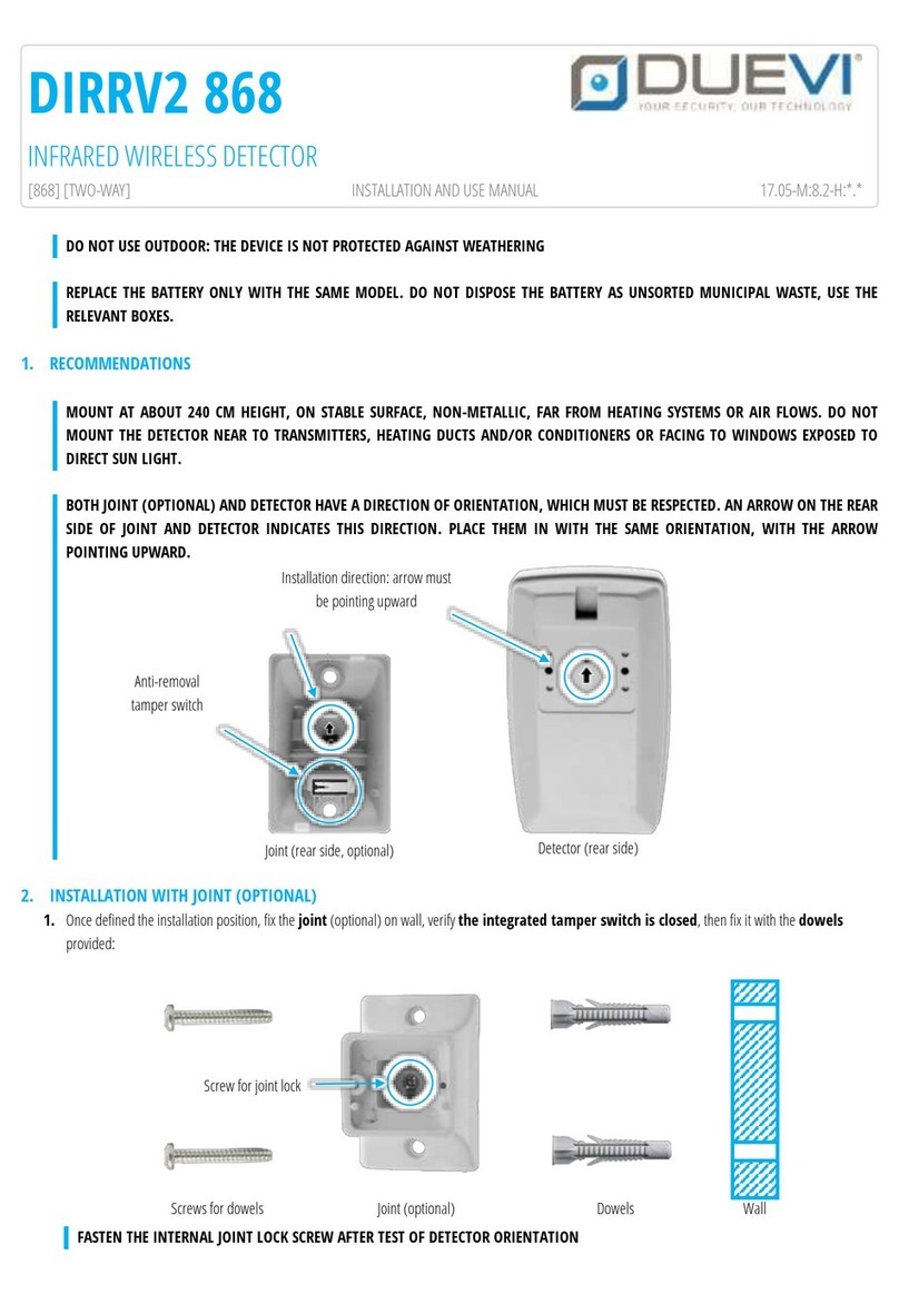
DO NOT USE OUTDOOR: THE DEVICE IS NOT PROTECTED AGAINST WEATHERING
REPLACE THE BATTERY ONLY WITH THE SAME MODEL. DO NOT DISPOSE THE BATTERY AS UNSORTED MUNICIPAL WASTE, USE THE
RELEVANT BOXES.
1. RECOMMENDATIONS
MOUNT AT ABOUT 240 CM HEIGHT, ON STABLE SURFACE, NON-METALLIC, FAR FROM HEATING SYSTEMS OR AIR FLOWS. DO NOT
MOUNT THE DETECTOR NEAR TO TRANSMITTERS, HEATING DUCTS AND/OR CONDITIONERS OR FACING TO WINDOWS EXPOSED TO
DIRECT SUN LIGHT.
BOTH JOINT (OPTIONAL) AND DETECTOR HAVE A DIRECTION OF ORIENTATION, WHICH MUST BE RESPECTED. AN ARROW ON THE REAR
SIDE OF JOINT AND DETECTOR INDICATES THIS DIRECTION. PLACE THEM IN WITH THE SAME ORIENTATION, WITH THE ARROW
POINTING UPWARD.
2. INSTALLATION WITH JOINT (OPTIONAL)
1. Once defined the installation position, fix the joint (optional) on wall, verify the integrated tamper switch is closed, then fix it with the dowels
provided:
FASTEN THE INTERNAL JOINT LOCK SCREW AFTER TEST OF DETECTOR ORIENTATION
DIRRV2
INFRARED WIRELESS DETECTOR
[SMD] [48bit] [SPV] [AN] INSTALLATION AND USE MANUAL 15.03-M:8.2-H:SE-04v2-13
Screws for dowels
Joint (optional)
Wall
Dowels
Screw for joint lock
Installation direction: arrow must
be pointing upward
Detector (rear side)
Joint (rear side, optional)
Anti-removal
tamper switch
2. Open the detector, remove the cover and unscrew the battery bracket
3. Make a 7 mm hole on frame and fix the detector to the joint, aligning the joint with the frame of the sensor and pass the cable inside:
4. Unscrew the electronic board from its place and pass the anti-removal switch cable inside the hole for cable (there is the battery cable) as in next figure:
5. Mount the electronic board and the battery bracket in their place. Connect the anti-removal tamper cable to the TMP.BR terminal. Activate the
detector (settings and battery) then close the cover. The installation is complete.
Hole for cables: battery and anti-
removal tamper
The anti-removal cable must be
maintained under the electronic board
Anti-removal cable: connect to
TMP.BR terminal
3. TECHNICAL
4. SUPERVISION
To enable, open the J.SPV jumper (see figure).
5. TAMPER
The sensor has two tamper protections:
ANTI-REMOVAL (JOINT): N.O. microswitch placed on joint, which is opened when the detector is removed from wall. The anti-removal cable must be
connected to the TMP.BR terminal. This tamper is controlled by jumper J.TMP.
ANTI-OPENING (COVER): N.O. microswitch on electronic board which is opened when the cover is removed. This tamper is controlled by DIP3.
NOTE: THE TWO TAMPERS ARE CONNECTED IN SERIES. THE NOT-USED TAMPER MUST ALWAYS BE DISABLED.
6. SENSOR CALIBRATION
Unplug the battery from detector
Set DIP4 to ON (LED ON) and DIP1 to OFF (TEST mode)
Plug the battery, wait 2 minutes (detector stabilization) and close the cover
ON
OFF
DIP1
Mode
Normal
Test
DIP2
Pulse count
2 pulses
(low sensitivity)
1 pulse
(high sensitivity)
DIP3
COVER Tamper
Disabled
Enabled
DIP4
LED
ON
OFF
OPENED
CLOSED
J.TMP
Anti-removal/Joint Tamper
Enabled
Disabled
J.SPV
Supervision
YES
NO
POWER
9 V alkaline battery (mod. BAT9)
FREQUENCY
433,92 MHz
RADIO RANGE
100 m (open field)
DETECTION RANGE
Max distance: 10 m | Beam angle: 110°
ABSORPTION
Stand-by: 8 µA | Transmission: 11 mA
AUTONOMY
About 8000 detections (about 2 years)
DIMENSION
68 x 112 x 45 mm (without joint)
Test the detector (detection and radio range) placing it in the installation point.
After each sensitivity adjustment (acting on trimmer) wait some seconds the detector stabilization:
•turn trimmer clockwise to increase sensitivity
•turn trimmer counter clockwise to decrease the sensitivity
When “pulse count” is set to 2 (DIP2 to ON) the sensitivity is lower.
Once finished adjustments, the detector MUST be set in NORMAL working mode (DIP1 to ON)
If necessary, change the installation point and detector orientation.
7. NORMAL WORKING
Set DIP4 to OFF (LED OFF) and DIP1 to ON (NORMAL mode) to have low absorption. Fix the detector in the position identified by testing phase and close the cover.
When in NORMAL mode, the detector sends alarm only after three minutes of complete absence of movement.
The detector has max detection sensitivity when its detection area is crossed in a transversal way (perpendicular to the sensor).
8. LEARNING
1. On control panel/receiver: enter in radio zone learning (“learning by tamper”or “AN” mode)
2. Plug the battery on detector
3. Set DIP3 to OFF (anti-opening tamper enabled) and close the jumper J.TMP (anti-removal tamper disabled)
4. With no other radio transmission (example: detection), press and hold the tamper switch TMP.CO (verify the control panel learnt the detector radio code)
Note: it is possible to learn the detector using “detection”learning mode on devices, which not use the “tamper” learning mode
THIS DEVICE MEETS THE R&TTE REQUIREMENTS (EUROPEAN UNION)
MADE IN ITALY