2
Installation and Operation of: Hot Frost Light Kits
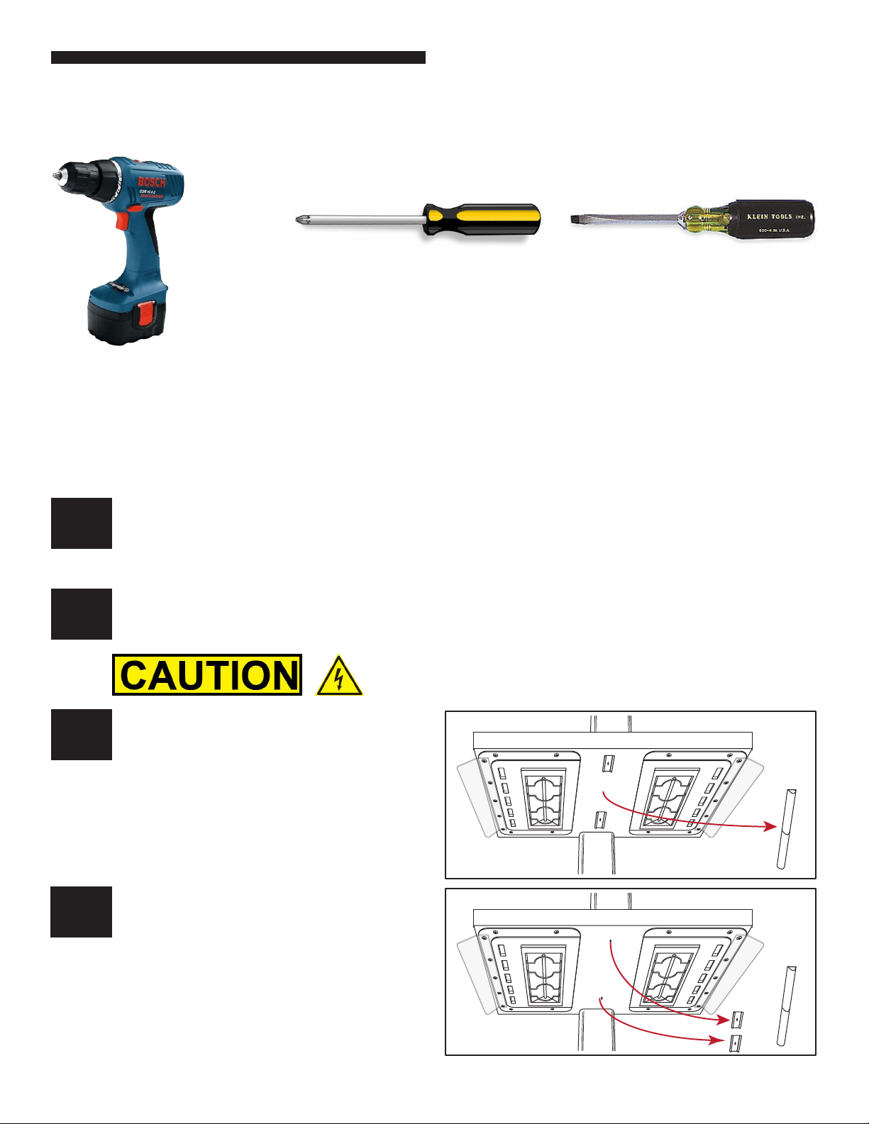
PARTS INCLUDED
3
2
5
4
6
NUMBER OF PARTS VARY BY KIT
Item Part
Number Description 114332
35” Unit
114333
48” - 50” Units
114334
64” Unit
114335
91” Unit
1 114074 75W LED Power Supply 1 1 1 1
2114179 LED Light 8” CW 2.4W 12 20 24 36
3 114058 LED Switch 2 2 2 2
4114180 LED Power Cord 4 4 4 4
5 0337210 1” X 108’VHB Dbl Side Tape 1 1 1 1
6 114181 Magnetic Mounting Clips 14 22 26 38
7* 114182 12” Connecting Cable* N/A N/A N/A 2
8* Various Mounting Plate 1 1 1 1
9* 213032 Screws, 8-18X1/2”TEK PHIL 6 10 12 20
10* PT3003190 #29 Drill Bit 1 1 1 1
* Not Shown