Dunham-Bush Smart-Vent User manual

Smart-Vent
Network Panel IOM Instructions
Dunham-Bush Ltd, Downley Road, Havant, Hants PO9 2JD
Document Ref:
023 9247 7700
info@dunham-bush.co.uk
121-000-015-B
UK:www.dunham-bush.co.uk
Global:www.dunham-bush.com
March 2020
Page 1 of 8
INSTALLER: Please leave these instructions, wiring diagram & access panel keys with the user.
1.0 Introduction
1.1 This booklet provides guidance to identify, handle, install, commission, operate and maintain Dunham-Bush
Smart-Vent network panel. The instructions apply to the standard panel only.
Please study the instructions carefully before commencing any installation work.
1.2 The Smart-Vent network panel is supplied as a single item, to enable complete system control of Smart-Vector
units. It is ordered and supplied as a separate accessory to Smart-Vector room units and includes an external
air temperature sensor, supplied loose for installation and wiring on-site.
Diagram 1: Smart-Vent network panel.
1.3 The panel is fitted with:
a) touch-screen user control of timeclock
schedule settings
b) timeclock override button with 1, 2, 3, 4 and
5 hour options
c) Pre-Purge enable switch
d) Day Time Cooling enable switch
e) Night Time Cooling enable switch
1.4 Smart-Vent should be connected to individual
Smart-Vector master units via their room controllers
by a single cable using RS485 polarity dependent
protocol.
1.5 When operating, Smart-Vent control will override all
the control strategy on individual Smart-Vector room
controllers.
1.6 If the Smart-Vent controller is disabled, disconnected
or switched off, Smart-Vector units will continue to
operate as stand-alone units, with their room
controller strategies
activated

Page 2 of 8
Diagram 2: Smart-Vent network panel dimensions and weight

Page 3 of 8
2.0 Handling, Storage & Preparation
2.1
Handling
- The purchaser is responsible for off-loading. Panels are individually packed and one person can
usually handle a single panel. The panel must not be dropped or suffer impact in any circumstances.
2.2
Storage
- The panel should be stored in clean, dry conditions. Any packaging should not be removed until the
panel is required for installation and should only be removed if damage is suspected at delivery
2.3 Preparation -
Make proper provision for fixings. The structure to which panel is to be fixed must be fit for
purpose and capable of accepting plugs and screws or suitable anchors. Suitable cable entry and glands
should be provided and electrical wiring should have been completed as far as possible.
3.0 Installing & Wiring to Smart-Vent Network Panel
3.1 See Diagram 2 for panel dimensions and weight. The panel can be fixed to a vertical wall surface, using normal
fixings that are suitable for wall construction.
3.2 It is recommended that the panel is sited between 1.0 –1.5m above floor level, in a location away from public
access e.g. facilities office, plant room, administration area.
3.3 Subject to fixings used, it is recommended that four holes are drilled in the back of the panel. The panel door
can be removed, but will require disconnection of the five door-mounted items.
3.5 The outside air temperature sensor is supplied loose; it should be fitted to an external wall in a suitable location
to measure outside air temperature. It should be site away from windows and other ventilation openings, on a
suitably shaded wall surface out of sunlight, typically minimum 2m above ground level.
3.4 After fitting panel and air sensor, connect panel to 230VAC mains supply (isolated and fused) and wire the
sensor back to the panel. Connect the panel to all room controllers, using a suitable RS-485 screened cable in
a daisy chain configuration, observing polarity rules.

Page 4 of 8
Diagram 3: Typical wiring diagram for Smart-Vent network panel.
NOTE: ALWAYS USE WIRING DIAGRAM ENCLOSED WITH THE PANEL

Page 5 of 8
4.0 Configuring Smart-Vector Room Controllers
Diagram 4: Smart-Vector Room Controller fascia Diagram 5: Location of binary “bit” switches
4.1 Before Smart-Vent network panel can be used, each room controller must be configured with a network
address, using the binary “bit-switches” on each room controller. A maximum of 20 addresses can be
configured with the switches.
4.2 Carefully remove the room controller fascia, by prising and unclipping it from the bottom.
4.3 The binary switches are located below the controller display, numbered 1 to 8 (See diagram 4). A switch is on
in the “up” position.
4.4 Switch nos. 1-5 are used to set the network address; switch no. 6 is not used; switch nos. 7 and 8 are used to
set the baud rate at 19200
4.5 Set the network address (room or controller number) and the baud rate using the table below
Switch No.
Binary
Value
Network
Room / Controller No.
1
2
3
4
5
6
7
8
9
10
11
12
13
14
15
16
17
18
19
20
1
1
Set all switches off
ON
ON
ON
ON
ON
ON
ON
ON
ON
ON
2
2
ON
ON
ON
ON
ON
ON
ON
ON
ON
ON
3
4
ON
ON
ON
ON
ON
ON
ON
ON
ON
4
8
ON
ON
ON
ON
ON
ON
ON
ON
5
16
ON
ON
ON
ON
ON
6
32
Switch Not Used
7
n/a
8
n/a
ON
ON
ON
ON
ON
ON
ON
ON
ON
ON
ON
ON
ON
ON
ON
ON
ON
ON
ON
ON
4.6 When switches are set, replace the room controller cover.

Page 6 of 8
5.0 Setting Day Time (Occupied) and Night Time Schedules
5.1 Timeclock schedules for day and night time can be set via 3.5” touchscreen
display. The Main Screen is shown in Diagram 6.
5.2 Select the room temperature display to enter the Menu Screen
(See Diagram 9).
5.3 Select the gearwheel icon at the bottom of the screen to enter Admin
Settings Screen (Diagram 7). Select System Menu enter the password
as requested (default 6666)
5.4 Check the following settings
Baud rate is 19200
Modbus address is 100
If required, select the setting and enter these settings.
5.5 Select Return to return to Main Screen
5.6 Select the calendar icon to enter the Calendar Schedule
5.7 Select the first day and set the times that rooms are to be occupied.
5.8 To copy the occupied times to another day, select Copy and the
source day to be copied. The source day will highlight in red.
5.9 Select the target days which will highlight in white.
5.10 Select Copy again to copy the occupied times to the required days.
5.11 Select Return to return the Main Screen.
Diagram 6: Home Screen
Diagram 7: Admin
Settings
Diagram 8: Calendar
Schedule

Page 7 of 8
5.0 Setting Day Time (Occupied) and Night Time Schedules cont.
5.12 To change the system date and time, select the clock icon.
5.13 Check and revise the system date and time.
5.14 Select the Return button to return to the Main Screen.
5.15 To clean the touchscreen, select Clean Screen. The touchscreen will be
disabled for 30 seconds to allow the screen to be cleaned.
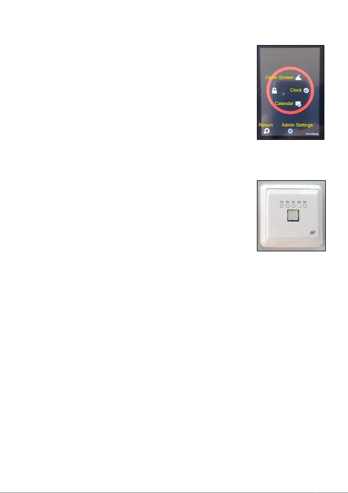
5.16 Diagram 9 shows the Menu Screen and relevant icons.
Diagram 9: Menu Screen
6.0 User Controls
6.1 User controls allow the day time (occupied) and night time settings to be
overridden, using the controls described below.
6.2
Timeclock Override Button
This button enables the daytime schedule to be extended up to five hours.
Press the button to cycle through the override periods (1h, 2h, 3h, 4h, 5h).
A green LED will indicate the selected override period; to return to
normal timeclock schedule, press the button to cycle through the periods
until no LED is lit.
6.3
Pre-Purge Switch
.
When enabled, all Smart-Vector units are run at full speed for 30 minutes
prior to start of daytime (occupied) schedule. On all Smart-Vector units, the
fresh air dampers fully open and fans run to purge treated spaces with fresh
air. Individual units are fitted with frost protection thermostats, which may
override fresh air dampers to circulate room air only
6.4
Day Time (Occupied) Cooling mode
When enabled, all Smart-Vector units will provide “free-cooling” by running
at full speed with fresh air dampers open, if room air temperature is more
than 1K above outside air temperature
and
above temperature setpoint.
Timeclock schedule for day time is user-programmable via the touch screen
and room temperature setpoint is user-adjustable via Smart-Vent room
controllers, with +/- 3K user adjustment
6.5
Night Time Cooling mode
When enabled, all Smart-Vector units will provide “free-cooling” by running at
full speed with fresh air dampers open, if room air temperature is more than
1K above outside air temperature. Timeclock schedule for night time is
user-programmable via the touch screen and room temperature setpoint is
user-adjustable via Smart-Vent room controllers, with +/- 3K user
adjustment.
Diagram 10: Timeclock
Override Button

Page 8 of 8
7.0 System Tests
7.1 Input the times from this table to ensure Smart -Vent is working correctly. Replace the outside temperature
sensor with a potentiometer to simulate outside air temperature.
(NOTE: Smart-Vent should be to powered off during air sensor change-over).
7.2 Adjust the following settings to carry out the required test:
OAT Outside Air Temperature; adjust using the potentiometer
PP Pre-Purge; enabled using the switch
DTFC Daytime Free-Cooling; enabled using the switch
NTFC Night-time Free-Cooling; enabled using the switch
CO₂Use a CO₂spray or breathe on the sensor on Smart-Vector room controller
SETPOINT Adjust on the Smart Vector Controller
Test
Time
SETTINGS
Expected Results
OAT
Pre-Purge
DTFC
NTFC
CO₂
SETPOINT
Fan(s)
Damper
Pre-Purge
05:28
MID
ON
OFF
OFF
LOW
MID
OFF
CLOSED
05:32
MID
ON
OFF
OFF
LOW
MID
ON
OPEN
05:45
MID
OFF
OFF
OFF
LOW
MID
OFF
CLOSED
DTFC
05:45
MID
OFF
ON
OFF
LOW
LOW
OFF
CLOSED
06:15
MID
OFF
ON
OFF
LOW
LOW
ON
OPEN
06:15
MID
OFF
OFF
OFF
LOW
LOW
OFF
CLOSED
06:15
MID
OFF
ON
OFF
LOW
HIGH
OFF
CLOSED
NTFC
17:15
MID
OFF
OFF
ON
LOW
LOW
OFF
CLOSED
18:15
MID
OFF
OFF
ON
LOW
LOW
ON
OPEN
18:15
MID
OFF
OFF
OFF
LOW
LOW
OFF
CLOSED
18:15
MID
OFF
OFF
ON
LOW
HIGH
OFF
CLOSED
CO₂
06:15
MID
OFF
OFF
OFF
LOW
MID
OFF
CLOSED
06:15
MID
OFF
OFF
OFF
HIGH
MID
ON
OPEN
OAT
05:32
LOW
ON
ON
ON
LOW
MID
OFF
CLOSED
06:15
LOW
ON
ON
ON
LOW
MID
OFF
CLOSED
18:15
LOW
ON
ON
ON
LOW
MID
OFF
CLOSED
06:15
LOW
ON
ON
ON
HIGH
MID
ON
OPEN
Note:
i) Where the OAT is Low it requires to be less than 10°C
ii) Tests above assume day time (occupied) times are 06:00 –18:00, adjust to suite timeclock schedule
iii) Reconnect outside air sensor when tests are complete
iv) Return timeclock schedule to its desired settings
SPARES/SERVICE
PLEASE WRITE THE DETAILS OF THE UNIT HERE.
These details will be required when ordering spares for you Dunham-Bush Smart-Vector network panel
UNIT TYPE AND MODEL INFORMATION
SERIAL NUMBER
DATE OF INSTALLATION
Spare parts/service –Please contact our office, contact information shown on page 1
Manufacturer reserves the right to change any product specification without notice
Table of contents
Popular Network Hardware manuals by other brands

Silex technology
Silex technology SX-500 Series instructions

Paradyne
Paradyne HotWire 7924 user guide

Paradyne
Paradyne Application Module 9109 OCU-DP installation instructions

KonNad
KonNad C2000-RSDD-CK-CK31 user manual

ADC
ADC HRE-204 List 1 user manual

ATTO Technology
ATTO Technology iPBridge 1550 Specifications

axing
axing EoC 1-11 Operation instructions

Leonton
Leonton REG5-2602-2C Series Hardware user manual

E+E Elektronik
E+E Elektronik EE240 user manual

GL Communications
GL Communications PacketExpert 10G Quick Verification Guide

Lindsay Broadband
Lindsay Broadband LBON300AC Series INSTALLATION AND OPERATION MANU

Oracle
Oracle Acme Packet 4600 Hardware installation and maintenance guide