manuals.online logo
Brands
  1. Home
  2. •
  3. Brands
  4. •
  5. Viking
  6. •
  7. Network Hardware
  8. •
  9. Viking TR-1 Instructions for use

Viking TR-1 Instructions for use

TR-1
TR-1
Programmable
Tone/Pulse
Toll Restrictor
March 15, 2004
P
Pr
ra
ac
ct
ti
ic
ce
e
T
TE
EL
LE
EC
CO
OM
MS
SO
OL
LU
UT
TI
IO
ON
NS
SF
FO
OR
RT
TH
HE
E2
21
1S
ST
TC
CE
EN
NT
TU
UR
RY
Y
TECHNICAL
TECHNICAL
Prevent Telephone Line Abuse with a
Programmable Toll Restrictor
h
ht
tt
tp
p:
:/
//
/w
ww
ww
w.
.v
vi
ik
ki
in
ng
ge
el
le
ec
ct
tr
ro
on
ni
ic
cs
s.
.c
co
om
m
• Phone line powered
• Non-volatile E2memory
• Compatible with Touch Tone or rotary phones
• .5 to 49.5 minute call timer with disconnect
• Programmable allow or restrict table stores up
to forty 12-digit phone numbers, prefixes or
area codes
• 6-digit bypass code for unrestricted access
•Programmable to ignore phone system line
access numbers
•Programmable ignore table stores up to
twelve 12-digit phone numbers, ideal for
✱67, ✱69, etc.
• Programmable maximum digit string length
• Concealed in a standard RJ11C jack
•Allow or restrict 1-800 numbers
• Operational alert tones
• Will not restrict dialing on inbound calls
• Allows emergency and toll free numbers !
F
Fe
ea
at
tu
ur
re
es
s
P
Ph
ho
on
ne
e.
..
..
.7
71
15
5.
.3
38
86
6.
.8
88
86
61
1
i
in
nf
fo
o@
@v
vi
ik
ki
in
ng
ge
el
le
ec
ct
tr
ro
on
ni
ic
cs
s.
.c
co
om
m
Power: Phone line powered (24V DC @ 20 mA minimum)
Dimensions: 70mm x 57mm x 22mm (2.75” x 2.25” x .88”)
Shipping Weight: .45 kg (1 lb)
Environmental: 0° C to 32° C (32° F to 90° F) with 5% to 95%
non-condensing humidity
Connections: Phone- (1) RJ11 jack, Line- (2) screw terminals
• Courtesy phones in banks, hotels, etc.
• Prevent outgoing calls on public phones, etc.
• Limit call times
• Force long distance calls through alternate
long distance carriers
• Prevent the use of hand held dialers
A
Ap
pp
pl
li
ic
ca
at
ti
io
on
ns
s
S
Sp
pe
ec
ci
if
fi
ic
ca
at
ti
io
on
ns
s
Carefully review all emergency numbers required for your area prior to installing the toll restrictor. These emergency numbers could include, 911, fire, police, rescue,
sheriff, poison center, etc. After installation of the toll restrictor is complete, make a test call to each of the emergency numbers for the area! This will allow you to
verify that you have not inadvertently blocked any required emergency numbers.
!
The TR-1 is a cost effective, user programmable Toll
Restrictor, ideal for applications where unauthorized
phone calls cannot be tolerated.
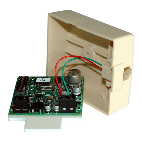
Concealed in a standard wall mount RJ11C jack, the
TR-1 is designed to allow or restrict local and/or
specified long distance numbers. The TR-1 provides
a 40-number allow/restrict table, a 6-digit bypass
code (allows authorized users unrestricted access),
and an inbound/outbound call timer with disconnect.
The TR-1 is Touch Tone program-
mable and will restrict Touch Tone
or pulse dialing on outbound calls.
Internal View
of the TR-1
I
In
ns
st
ta
al
ll
la
at
ti
io
on
n
P
Pr
ro
og
gr
ra
am
mm
mi
in
ng
g
A. Pre-Programmed Switch Selections
Note: The bypass code is factory set to 123456.The bypass code is a six-digit user programmable code which allows authorized persons to make a single
unrestricted call. To enable this feature the code must be preceded with a #. After receiving the code, the TR-1 will disconnect. One unrestricted call will be
allowed on the next off-hook condition. Note: If a #entered as the first digit from off-hook conflicts with your C.O. or phone system features, a single (allowed)
digit 1-9 may be entered prior to the #and bypass code. Example: Come off hook and dial #123456, two beeps will be heard, then hang-up. The next call will
be unrestricted. When that call is complete, hang up. The following calls will have full toll restriction.
Important: The TR-1
components are sensi-
tive to static electricity.
Personnel and the work
area should be ground-
ed before handling.
1. Disconnect all wires from the existing phone jack.
2. Set desired switch selections (see Programming section Abelow).
3. Connect the red and green wires from the phone jack to the J2 screw terminals.
4. Connect the red and green wires from the C.O. line to the J1 screw terminals.
5. Mount the TR-1 with the screw provided and connect phone to modular jack.
Note: Only the red and green wires are used. Tape any extra wires to prevent shorting.
DIP Switch
1
2
3
4
5
6
Set switch ON to restrict or OFF to allow the following numbers...
“976” Metered Toll Calls (976, 1-976, 1-XXX-976)
Long Distance (1-XXXXXX, 10)
Operator Assisted Calls (0+)
“900” Metered Toll Calls (1-900)
Directory Assistance (555, 1-555, 1-XXX-555, 411, 1-411)
For Centrex or PABX’s: Turn OFF to ignore the first 9 in 9+ dialing (programmable)
2. Operating Tones
With the call timer programmed, a double beep will be heard 30 seconds prior to time-out, followed by a triple beep immediately before the disconnect. The
TR-1 is capable of detecting hardware memory errors. If you come off hook and an error is detected, the unit will output 4 beeps and only allow 311 and
911 emergency dialing.
D. Accessing the Programming Mode
1. From a Touch Tone phone, call the phone connected to the TR-1 on a C.O. line or analog PABX/KSU station.
2. Answer the phone connected to the TR-1. Note: Programming can be done from the calling phone or from the phone connected to the TR-1.
3. Enter ✱+current six-digit security code (factory set to 845464). A double beep should be heard indicating programming mode has been
accessed. Note: If a
✱
entered as the first digit from off-hook conflicts with your C.O. or phone system features, a single (allowed) digit 1-9 may
be entered prior to the
✱
and six digit security code to enter programming. Example: 5
✱
845464
E. Security Code
The security code is a six-digit code that allows the user/installer to program the TR-1. To program your personal security code, follow step 1 below. Note:
The security code is factory set to 845464 (V-I-K-I-N-G).The security code cannot contain a
✱
or #and should not match the Bypass code.
1. Access the programming mode as explained in section D above and enter the new six-digit security code then enter #47.
G. Maximum Digit String Length
This programmable feature restricts the maximum number of digits allowed to be dialed. It can be set from 01-99. If a number longer than the maximum digit
length is entered, a triple beep will be heard and the call will be disconnected.
To Enable: Enter two digits (01-99) + #49 in programming. To Disable: Enter #49 in programming.
H. Call Timer
The call timer feature allows the TR-1 to automatically disconnect after a specified time. The timer begins with any dialing, Touch Tone or pulse. It can be pro-
grammed in 30 second increments (49.5 minutes maximum). When the call timer is enabled, a double beep will be heard 30 seconds prior to time out, fol-
lowed by a triple beep just before the disconnect. Note: With switch 6 OFF, numbers that do not start with 9 will not activate the call timer.
To Enable the Call Timer: Enter two digits (01-99) + #48.To Activate the Call Timer on Outbound Calls Only: Enter ✱6.
To Disable the Call Timer: Enter #48.To Activate the Call Timer on Inbound & Outbound Calls : Enter ✱7.
I. User Programmable Allow/Restrict Table
This table is used to store user-defined dialing strings (see Programming Features section P). It can store up to forty 12-digit allow or restrict numbers. This
table can be set to either allow or restrict; it cannot be set to do both simultaneously. This table is useful when you would like to allow or restrict specific num-
bers not covered by the switches 1-5. Note: This table has priority over the internal jumper programming.
J2
S1
14
3
2
ON
7
6
5
S1
14
3
2
ON
7
6
5
ON
OFF
J1
DIP Switches
(shown in factory settings)
B. Programming Switch 6 to Ignore Specific Outside Line Access Numbers
Switch 6 is factory set to ignore the first 9 in 9+ dialing. This feature is enabled by setting switch 6 to OFF. Switch 6 can be user programmed with up to eight
8-digit numbers. This feature is useful if you have an outside line access number other than “9” or multiple outside line access numbers. With this feature
enabled (switch 6 OFF), if the phone number dialed does not start with your programmed outside line access number (number programmed in switch 6), it is
allowed. This is useful for allowing extension dialing on phone systems. If the number dialed does start with the programmed line access number, all the dig-
its following the access number will be allowed or restricted according to the selected programming.
1. Access the programming mode as explained in section D.
2. Enter your 1-8 digit line access number + ## + 6+ the position 1-8.
3. Repeat step 3 for each line access number programmed (up to 8 positions).
4. Set switch 6 to OFF to enable the “Ignore Line Access Number” features programmed in step 2.
C. Operational Alert Tones
During programming, a double beep will be heard after entering a valid command or memory location. If an invalid command or number sequence is
entered, it will be indicated by a triple beep. If an error is made, review the instructions, and re-program that location.
1. Programming Tones
This table is used to store user-defined dialing strings. It can store up to twelve 12-digit Ignore numbers. This feature is useful for ignoring the first few digits
dialed such as Central Office control codes like “
✱
67” (block caller I.D. for one call). All digits dialed following the programmed ignore number will be allowed
or restricted according to the selected programming. Example: Programming the TR-1 to ignore “✱67”. Enter ✱✱67#60
J. User Programmable Ignore Table
F. Bypass Code
Red
Green
Red
Green
Restricted
Phone TR-1
C.O.
Line
Internal View of
the TR-1
The TR-1 has DIP switches (see diagram right) that restrict different types of factory default dialing
strings. Turning OFF the specified switch will ALLOW the dialing strings.
This mode is useful if you have forgotten your security code and need to enter programming. Set switches 1 and 2
to OFF, and set switch 7 to ON as shown in the diagram to the right. Have someone call the phone connected to the
TR-1. Answer and enter ✱followed by ANY six digits. Two beeps should be heard indicating you have entered the
programming mode. Enter your new security code (six digits + #47) and any other programming needed, then hang-
up and place the switches back to their original positions.
Note: With the TR-1 turned OFF, all dialing will be unrestricted.
4. Enter 20#48 (a double beep should be heard).
5. Enter 07#49 (a double beep should be heard).
6. Enter ✱7(a double beep should be heard).
7. Hang-up.
K. Wild Card
The wild card feature (
✱
1)is used to allow or restrict numbers 0-9 in that digit specified. For example, to restrict numbers 800, 810, 820, 830... simply pro-
gram the TR-1 with 8 ✱1 0 # + memory location. Note: With a
✱
or #as the 1st digit, the following six digits can NOT be a wild card (
✱
1).
L. Programming a ✱ora#
Since the TR-1 uses ✱and #for specific programming functions, you must enter ✱✱ to input a single ✱and ✱#to input a single # into the dialing string you
wish to allow or restrict. Note: A
✱
or #can NOT be programmed as the second digit, due to conflicts with the security and bypass codes.
M. Allow All Other/Restrict All Other Numbers
Allow all other numbers: Enter ✱4in programming. Restrict all other numbers: Enter ✱5 in programming.
Note: The TR-1 is factory set to allow all other numbers that are not programmed into the Allow/Restrict Table or covered by switches 1-5.
N. Entering Programming Without a Security Code
J1
J2
S1
14
3
2
ON
7
6
5
S1
14
3
2
ON
7
6
5
ON
OFF
Internal View
of the TR-1
Memory
Note:The User Programmable Allow/Restrict table can be set to Allow OR Restrict, NOT both simultaneously.
4. Enter ✱2(a double beep should be heard) ✱5(a double beep
should be heard).
5. Enter 1715#00 (a double beep should be heard).
6. Enter 1612#01 (a double beep should be heard).
7. Enter 1414#02 (a double beep should be heard).
8. Hang-up.
4. Enter ✱2(a double beep should be heard) ✱5(a double beep
should be heard).
5. Enter 7✱10#26 (a double beep should be heard).
6. Hang-up.
Note: When programming the TR-1, it is not necessary to hang-up and re-
enter programming to program the next memory location. All user pro-
gramming can be done consecutively.
P
Pr
ro
og
gr
ra
am
mm
mi
in
ng
gE
Ex
xa
am
mp
pl
le
es
s
To complete these examples, you must start by following steps 1-3:
1. Call the phone connected to the TR-1 on a C.O. line or analog PABX/KSU station.
2. Answer the phone connected to the TR-1. The following programming can be done by the calling phone or the phone connected to the TR-1.
3. Enter a ✱followed by the six-digit security code (factory set to 845464), a double beep should be heard.
B. Programming a New Security Code of 123456 and a Bypass
Code of 654321
4. Enter 123456#47 (a double beep should be heard).
5. Enter 654321#50 (a double beep should be heard).
6. Hang-up.
D. Programming the TR-1 with a Maximum Call Length of 10
Minutes for Inbound and Outbound Calls and the Capability of
Dialing Only 7 Digit Numbers
O. Turning On/Off the TR-1
Turn on the TR-1: Enter ✱9in programming. Turn off the TR-1: Enter ✱8 in programming.
P. Programming Features Quick Reference
E. Programming the TR-1 to Allow 1-715, 1-612 and 1-414 Area
Codes and Restrict All Other Numbers
A. Programming the TR-1 to Restrict All Outbound Calls,
Including 1-800 Calls
4. Enter ✱3(a double beep should be heard) ✱5(a double beep
should be heard).
5. Enter ✱08 (a double beep should be heard).
6. Hang-up.
C. Using the Wild Card Feature to Allow Only 700, 710, 720, 730,
740, 750, 760, 770, 780 and 790 Numbers in Location 26
Features
Programmable Allow/Restrict table (factory cleared) .................................................................................................
Clear a number in the Allow/Restrict table .................................................................................................................
Set all programming to factory default .......................................................................................................................
Set jumpers to factory default ....................................................................................................................................
Clear the entire allow/restrict table (positions 00 - 39) ...............................................................................................
Security code (factory set to 845464) ........................................................................................................................
Call timer (01 - 99 in 30 second increments, factory disabled) ...................................................................................
Maximum number of digits allowed to dial (01 - 99, factory disabled) ........................................................................
Bypass code (factory set to 123456) .........................................................................................................................
Clear the entire Ignore table (positions 60 - 71) .........................................................................................................
Programmable Ignore table (factory cleared) ............................................................................................................
Clear a number in the Ignore table ............................................................................................................................
Entering a single Touch Tone ✱.................................................................................................................................
Entering a single Touch Tone #..................................................................................................................................
Clear all numbers programmed in switch 6 ...............................................................................................................
Allow toll-free numbers 800, 822, 833, 844, 855, 866, 877, 888 (factory setting) ......................................................
Restrict toll-free numbers 800, 822, 833, 844, 855, 866, 877, 888 ............................................................................
Entering a single digit Wild card ................................................................................................................................
Set user programmable table to Allow .......................................................................................................................
Set user programmable table to Restrict (factory setting) ..........................................................................................
Allow all other numbers (factory setting) ....................................................................................................................
Restrict all other numbers .........................................................................................................................................
Activate call timer on outbound calls only (factory setting) ........................................................................................
Activate call timer on inbound and outbound calls .....................................................................................................
Turn the TR-1 off .......................................................................................................................................................
Turn the TR-1 on (factory setting) ..............................................................................................................................
Jumper 6 PABX line access numbers (factory set to 9) .............................................................................................
Digits
1 - 12 digits ......
(none) ..............
6 digits .............
2 digits .............
6 digits .............
(none) ..............
1 - 12 digits ......
(none) ..............
✱✱
✱#
✱06
✱07
✱08
✱1
✱2
✱3
✱4
✱5
✱6
✱7
✱8
✱9
+ Location
+ #00 to #39
+ #00 to #39
+ #44
+ #45
+ #46
+ #47
+ #48
+ #49
+ #50
+ #51
+ #60 to #71
+ #60 to #71
1-8 digits + ##+6+position 1-8
Number
______________(6-digits) #47 Security Code
_____ (2-digits) #48 Maximum time limit
_____ (2-digits) #49 Maximum digit length
______________(6-digits) #50 Bypass Code
Due to the dynamic nature of the product design, the information contained in this document is subject to change without notice. Viking Electronics, and its affiliates and/or
subsidiaries assume no responsibility for errors and omissions contained in this information. Revisions of this document or new editions of it may be issued to incorporate
such changes.
Fax Back Doc 705
ZF301980 Rev A
Printed in the U.S.A.
Q. User Programmable Allow/Restrict Table
For your records and ease in programming, write down the numbers and check off the features in the spaces below before pro-
gramming. Note: If you want to restrict/allow a number that begins with the digit 1, you must program the digit “1” first. Example:
17153868861.
Number (1-12 digits) Location
________________________ #00
________________________ #01
________________________ #02
________________________ #03
________________________ #04
________________________ #05
________________________ #06
________________________ #07
________________________ #08
________________________ #09
________________________ #10
________________________ #11
________________________ #12
________________________ #13
________________________ #14
________________________ #15
________________________ #16
________________________ #17
________________________ #18
________________________ #19
Number (1-12 digits) Location
________________________ #20
________________________ #21
________________________ #22
________________________ #23
________________________ #24
________________________ #25
________________________ #26
________________________ #27
________________________ #28
________________________ #29
________________________ #30
________________________ #31
________________________ #32
________________________ #33
________________________ #34
________________________ #35
________________________ #36
________________________ #37
________________________ #38
________________________ #39
Check the Features in Use
____ ✱2 Set user programmable table to allow
____ ✱3 Set user programmable table to restrict
____ ✱4 Set all other numbers to allow
____ ✱5 Set all other numbers to restrict
____ ✱6 Enable call timer on outbound calls only
____ ✱7 Enable call timer from off-hook
____ ✱8 Turn TR-1 off
____ ✱9 Turn TR-1 on
____ ✱07 Allow 1-800 numbers
____ ✱08 Restrict 1-800 numbers
P
Pr
ro
od
du
uc
ct
tS
Su
up
pp
po
or
rt
tL
Li
in
ne
e.
..
..
.7
71
15
5.
.3
38
86
6.
.8
86
66
66
6F
Fa
ax
xB
Ba
ac
ck
kL
Li
in
ne
e.
..
..
.7
71
15
5.
.3
38
86
6.
.4
43
34
45
5
(Ignore PABX Line Access Numbers)
____ Disabled (Switch ON)
____ Enabled (Switch OFF)
Position: Number (1-8 digits) Location
1. ___________________ ##61
2. ___________________ ##62
3. ___________________ ##63
4. ___________________ ##64
5. ___________________ ##65
6. ___________________ ##66
7. ___________________ ##67
8. ___________________ ##68
F
FC
CC
CR
Re
eq
qu
ui
ir
re
em
me
en
nt
ts
s
Type of Service
The TR-1 is designed to be used on standard device telephone lines. The TR-1 is connected to the telephone line by
means of a screw terminal. Connection to telephone company-provided coin service (central office implemented sys-
tems) is prohibited. Connection to party line service is subject to State tariffs.
Telephone Company Procedures
The goal of the telephone company is to provide you with the best service it can. In order to do this it may occasionally
be necessary for them to make changes in their equipment, operations, or procedures. If these changes affect your serv-
ice of the operation equipment, the telephone company will give you notice in writing, allowing you to make any changes
necessary to maintain uninterrupted service. If you have any questions about your telephone line, such as, how many
pieces of equipment you can connect to it, the telephone company will provide you information upon request. In certain
circumstances, it may be necessary for the telephone company to request information from you, concerning the equip-
ment which is connected to your telephone line. Upon request request of the telephone company, provide the FCC reg-
istration number and the ringer equivalence number (REN) of the equipment which is connected to your line; both of
these items are listed on the equipment label. The sum of all the REN’s on your telephone lines should be less than five
in order to assure proper service from your telephone company. In some cases, a sum of five may not be usable on a
given line.
R. User Programmable Ignore Table
Number (1-12 digits) Location
________________________ #60
________________________ #61
________________________ #62
________________________ #63
________________________ #64
________________________ #65
Number (1-12 digits) Location
________________________ #66
________________________ #67
________________________ #68
________________________ #69
________________________ #70
________________________ #71
S. Switch 6 Programming
If Problems Arise
If any of your telephone equipment is not operating properly, you should immediately remove it from your telephone line
as it may cause harm to the telephone network. If the telephone company notes a problem, they may temporarily dis-
continue service. When practical, they will notify you in advance of this disconnection. If notified, you will be given the
opportunity to correct the problem and informed of your right to file a complaint with the FCC.
In the event repairs are ever needed on your Viking product, they should be performed by Viking Electronics, Inc. and
or an authorized representative of Viking Electronic, Inc.. For more information contact Viking Product Support at
(715)386-8666.
FCC Part 15 Limitations
This equipment has been tested and found to comply with the limits for a Class A digital device, pursuant to Part 15 of
the FCC Rules. These limits are designed to provide reasonable protection against harmful interference when the
equipment is operated in a commercial environment. This equipment generates, uses, and can radiate radio frequen-
cy energy and, if not installed and used in accordance with the instruction manual, may cause harmful interference to
radio communications. Operation of this equipment in a residential area is likely to cause harmful interference in which
case the user will have to correct the interference at his own expense.
Other Viking Network Hardware manuals

Viking TDR-1 Instructions for use

Viking

Viking TDR-1 Instructions for use

Viking DVA-1003B Instructions for use

Viking

Viking DVA-1003B Instructions for use

Viking CPC-1 Instructions for use

Viking

Viking CPC-1 Instructions for use

Viking E-1600A series Installation and operating instructions

Viking

Viking E-1600A series Installation and operating instructions

Viking DVA-500A Instructions for use

Viking

Viking DVA-500A Instructions for use

Viking DVA-1003B Installation and operating instructions

Viking

Viking DVA-1003B Installation and operating instructions

Viking DNA-510 Instructions for use

Viking

Viking DNA-510 Instructions for use

Viking DNA-510 Instructions for use

Viking

Viking DNA-510 Instructions for use

Viking W-1000 Installation and operating instructions

Viking

Viking W-1000 Installation and operating instructions

Viking DVA-2WA Installation and operating instructions

Viking

Viking DVA-2WA Installation and operating instructions

Viking TR-1 Installation and operating instructions

Viking

Viking TR-1 Installation and operating instructions

Viking DVA-500 Instructions for use

Viking

Viking DVA-500 Instructions for use

Viking DVA-1003B Installation and operating instructions

Viking

Viking DVA-1003B Installation and operating instructions

Viking DVA-2WA Instructions for use

Viking

Viking DVA-2WA Instructions for use

Viking CPA-7B Installation and operating instructions

Viking

Viking CPA-7B Installation and operating instructions

Viking DVA-1002 Instructions for use

Viking

Viking DVA-1002 Instructions for use

Viking CPC-4 Instructions for use

Viking

Viking CPC-4 Instructions for use

Viking ONYX Series Installation instructions

Viking

Viking ONYX Series Installation instructions

Viking DVA-3003 Instructions for use

Viking

Viking DVA-3003 Instructions for use

Viking DVA-1003A Instructions for use

Viking

Viking DVA-1003A Instructions for use

Viking CTG-2 Instructions for use

Viking

Viking CTG-2 Instructions for use

Viking CPA-7B Installation and operating instructions

Viking

Viking CPA-7B Installation and operating instructions

Viking DVA-1003B User manual

Viking

Viking DVA-1003B User manual

Popular Network Hardware manuals by other brands

ATV DR-6232H-8TB Operation manual

ATV

ATV DR-6232H-8TB Operation manual

Positron G1002-M Self-installation guide

Positron

Positron G1002-M Self-installation guide

LG S1T1 user manual

LG

LG S1T1 user manual

Castelle Premier user guide

Castelle

Castelle Premier user guide

Iomega StorCenter ix4-200d user guide

Iomega

Iomega StorCenter ix4-200d user guide

TRENDnet TV-NVR416 user guide

TRENDnet

TRENDnet TV-NVR416 user guide

VIPA CP 1413plus manual

VIPA

VIPA CP 1413plus manual

Panasonic Photo IC PNA4601M Specifications

Panasonic

Panasonic Photo IC PNA4601M Specifications

Precision Digital Corporation PDW30 instruction manual

Precision Digital Corporation

Precision Digital Corporation PDW30 instruction manual

Abocom CR2000 Specification sheet

Abocom

Abocom CR2000 Specification sheet

Huawei LSBM1SRP Specifications

Huawei

Huawei LSBM1SRP Specifications

ADTRAN 3.125 Gigabit Ethernet Job aid

ADTRAN

ADTRAN 3.125 Gigabit Ethernet Job aid

Hillstone SG-6000 X Series Hardware reference guide

Hillstone

Hillstone SG-6000 X Series Hardware reference guide

Costar CR8020XDi quick guide

Costar

Costar CR8020XDi quick guide

Emerson AXP 1410 Installation and use

Emerson

Emerson AXP 1410 Installation and use

Cabletron Systems CBUPRI/E1 user manual

Cabletron Systems

Cabletron Systems CBUPRI/E1 user manual

Korenix JetNet 2205 Quick installation guide

Korenix

Korenix JetNet 2205 Quick installation guide

WatchNet ENM-04 POE Quick connection guide

WatchNet

WatchNet ENM-04 POE Quick connection guide

manuals.online logo
manuals.online logoBrands
  • About & Mission
  • Contact us
  • Privacy Policy
  • Terms and Conditions

Copyright 2025 Manuals.Online. All Rights Reserved.