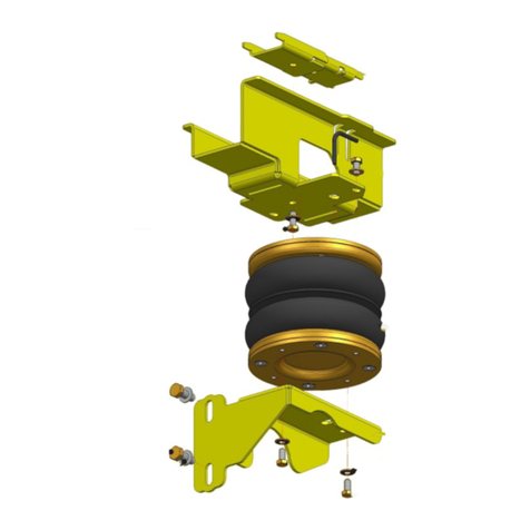
5.3 BUMP STOP REMOVAL AND FITTING OF UPPER BRACKET ASSEMBLY
1. Remove the bump stop—Figures 1 to 3
2. Insert the two small ‘shoe’ plates into the frame left vacant by removal of the bump stops—Figures 4 and 5
3. Offer the largest part of the upper bracket assembly up to the ‘shoe’ plates. Attach the bracket to the
plates using two M8 x 20mm countersunk bolts—Figures 6 and 7
4. See Figures 8, 9, 10 and 11 : Install three M8 x 20mm bolts to (a) attach the ‘rib’ bracket to the upper bracket
assembly and (b) secure the upper bracket assembly against the chassis. Note that the two uppermost
bolts are tightened until they abut a small plate placed between the bracket and the chassis. This plate
serves to protect the coating of the chassis rail from being marked by the bolt ends.
5.4 FITTING OF BELLOW TO UPPER BRACKET ASSEMBLY
1. See Section 5.9 - “Tube Connection and Disconnection, Cutting and Routing” : Connect a tube to the
bellow. Use black tubing for the left-hand bellow and blue for the right-hand bellow.
2. Manually compress the bellow and then bung the end of the tube to maintain the compressed state
3. Feed the tube through the slot in the upper bracket and offer the bellow up to the bracket. Secure the
bellow to the upper bracket using an M8 x 16mm bolt and an M8 disc spring washer, and an M8 x 20
countersunk screw (already installed in the air bellows) —Figures 12 to 15 inclusive. Do not fully tighten at
this stage because the bellow may require alignment once inflated (see Section 5.11, Figure 30).
5.5 FITTING OF LOWER BRACKET
1. Remove the two bolts from the bracket that attaches the torsion beam assembly to the axle—Figures 16
and 17
2. Place the lower bracket over the axle then reattach the bracket that secures the torsion beam assembly to
the axle, thereby also securing the lower bracket to the axle—Figures 18 and 19
5.6 FITTING OF BELLOW TO LOWER BRACKET
1. Release the bung from the tube. This allows air into the bellow, which consequently expands downwards
towards the lower bracket—Figures 20 and 21.
2. Attach the lower bracket to the bellow using two M8 x 16mm bolts and two serrated washers—Figures 22
and 23. Do not fully tighten at this stage because the bellow may require alignment once inflated (see
Section 5.11, Figure 30).
5.7 MODIFICATION OF LOAD SENSING VALVE (LSV) ASSEMBLY
1. Disconnect and remove the load sensing valve linkage and arm, but retain the pin that connects the
linkage to the bracket at the top end—Figures 24, 25 and 26
2. Using the pin retained from the previous step, install the small adaptor bracket. Place the hook on the
open end of the LSV spring through the hole in the adaptor bracket—Figures 27 and 28
3. Loosen the LSV spring retaining nut and adjust as necessary to achieve the 233mm dimension as shown
in Figure 29. Once this dimension is achieved, re-tighten the retaining nut.
10 | INSTALLATION MANUAL | AUXILIARY AIR SUSPENSION | SPRINTER 408D/416CDI AND 4X4 / VOLKSWAGEN LT-46 AND 4X4 (1995-2006) JULY 2021
