Dunlop L.MAS.MOV.C.M User manual

www.dunlopsystems.nl
Auxiliary Air Suspension
November 2018
Installation Manual
DUNLOP and the Flying D Device are trademarks of Dunlop International Group and are used under license by DSC Nederland B.V.
L.MAS.MOV.C.M
Nissan Interstar, 1999 - 2010
Opel Movano, 1999 - 2010
Renault Mastervan, 1999 - 2010

L.MAS.MOV.C.M
Nissan Interstar Opel Movano Renault Mastervan
2
DUNLOP and the Flying D Device are trademarks of Dunlop International Group and are used under license by DSC Nederland B.V.
www.dunlopsystems.nl
1. FOREWORD .......................................................... 3
2. INTRODUCTION .................................................... 4
3. VERY IMPORTANT NOTES........................................ 5
4. COMPLETE ASSEMBLY ............................................ 7
5. INSTRUCTIONS FOR INSTALLATION......................... 8
5.1. Preliminary Step—LSV Spring Length Measurement .........................8
5.2. Bump Stop Removal and Fitting of Upper Plate................................8
5.3. Rerouting brake line....................................................................8
5.4. Fitting of Lower Bracket...............................................................9
5.5. Bellow Installation.......................................................................9
5.6. Fitting of Inflator Console...........................................................10
5.7. Tube Connection and Disconnection, Cutting and Routing ...............12
5.8. Spring Inflation.........................................................................13
5.9. Spring Alignment ......................................................................13
5.10. IMPORTANT! Load Sensing Valve (LSV) Adjustment ....................14
5.11. Maintenance...........................................................................14
5.12. Check List..............................................................................14
5.13. Installation Drawings...............................................................15
6. EPILOGUE ............................................................18
CONTENTS
DSC Nederland B.V.
Het Wegdam 22
7496 CA Hengevelde
Nederland
Tel. :+31 (0)547 333065
Fax.:+31 (0)547 333068
e-mail: [email protected]
Website: www.dunlopsystems.nl
© 2017, DSC Nederland B.V.

L.MAS.MOV.C.M
Nissan Interstar Opel Movano Renault Mastervan
3
DUNLOP and the Flying D Device are trademarks of Dunlop International Group and are used under license by DSC Nederland B.V.
www.dunlopsystems.nl
1. FOREWORD
This manual provides instructions for the installation of an auxiliary air
suspension kit, developed specifically for the Nissan Interstar, Opel
Movano and Renault Mastervan. To ensure correct installation of the kit,
it is strongly recommend that these instructions are read thoroughly
before commencing any installation work. Installation should only be
carried out by a suitably qualified mechanic or specialist installation
facility. DSC Nederland will not accept any responsibility for faults or
defects arising from incorrect installation, which automatically renders
the guarantee invalid.
This kit is suitable for motorhomes and other vehicles with a minimum
rear axle load of 1350kg (2975lbs).
IMPORTANT : Manufacturer’s Declaration Form
A manufacturer’s declaration form is provided with your kit.
Following installation of the kit please ensure that this form is
completed, signed by a qualified fitter and a copy is returned to
DSC Nederland by post, fax or e-mail. Our e-mail address is:

L.MAS.MOV.C.M
Nissan Interstar Opel Movano Renault Mastervan
4
DUNLOP and the Flying D Device are trademarks of Dunlop International Group and are used under license by DSC Nederland B.V.
www.dunlopsystems.nl
2. INTRODUCTION
Thank you for choosing an auxiliary air suspension kit from the range
offered by DSC Nederland Auxiliary air suspension is fitted in tandem
with the standard steel springs of the vehicle suspension, and provides
enhancements in terms of both the stability of the vehicle and the
comfort of the passengers…
Vehicle Levelling
Simply by varying the air pressure in the springs, the vehicle can be
levelled both front-to-rear and side-to-side. Keeping the vehicle
level optimises stability, ensures correct headlamp beam distribution
and reduces tyre wear arising from uneven distribution of weight.
Straight Line Stability
Straight line stability is greatly increased at higher speeds, and when
subjected to buffeting from cross-winds or large overtaking vehicles
Reduced Body Roll
Body roll when cornering or negotiating roundabouts is significantly
reduced.
Fatigue Reduction and Wear Compensation
Suspension fatigue is reduced, so helping to prevent leaf springs
from sagging under repeated or constant loading.
Any sagging already present can be compensated-for. This is a
particular benefit for motorhomes, which are always fully laden.
Ride Comfort
Air springs help to absorb shock loads from uneven road surfaces,
therefore general ride quality is much improved.

L.MAS.MOV.C.M
Nissan Interstar Opel Movano Renault Mastervan
5
DUNLOP and the Flying D Device are trademarks of Dunlop International Group and are used under license by DSC Nederland B.V.
www.dunlopsystems.nl
3. VERY IMPORTANT NOTES
Gross Vehicle Weight (GVW)
Air assist kits are not in themselves designed to increase
the gross vehicle weight (GVW) rating of a vehicle. They
do not legally allow for carriage of a load greater than the
carrying capacity stated on the data plate of the vehicle.
Do not exceed the maximum load specified by the vehicle
manufacturer…
to avoid compromising passenger safety
to prevent possible damage to the vehicle
for legal reasons
Load Sensing Valve (LSV) Adjustment
If your vehicle is not fitted with an antilock braking system
(ABS) then it will have a load sensing valve (LSV) to
automatically adjust braking force under varying load conditions.
This valve must be adjusted immediately after the fitting of an
air assist kit and before the vehicle is driven again on public
roads.
If the LSV is not adjusted following the fitting of an air assist kit,
it may misjudge rear load conditions to the extent that the
braking pressure applied to the rear brakes is not correct (e.g.
the rear wheels may lock with no load on the rear axle). The
consequences of this in terms of vehicle stability and safety are
potentially serious.
Vehicle Uprating
Despite the above words of caution, it is possible to upgrade the weight
rating of your vehicle. This must be carried-out by a specialist supplier
that will…
carry out any necessary modifications in addition to fitting the air
assist kit
complete documentation as necessary to inform the Vehicle and
Operator Services Agency (VOSA) – a mandatory requirement
supply and fit a new weight plate to replace the original plate
supplied with the vehicle
This process applies to United Kingdom registered vehicles. The process
in other countries may be different.

L.MAS.MOV.C.M
Nissan Interstar Opel Movano Renault Mastervan
6
DUNLOP and the Flying D Device are trademarks of Dunlop International Group and are used under license by DSC Nederland B.V.
www.dunlopsystems.nl
Safety Guidance Note
The following very useful guidance note is available for free download
from the Health and Safety Executive (HSE)…
PM85, July 2007 Safe recovery (and repair) of buses and coaches fitted
with air suspension
The uniform resource locator (URL) for this document is…
http://www.hse.gov.uk/PUBNS/pm85.pdf

L.MAS.MOV.C.M
Nissan Interstar Opel Movano Renault Mastervan
7
DUNLOP and the Flying D Device are trademarks of Dunlop International Group and are used under license by DSC Nederland B.V.
www.dunlopsystems.nl
4. COMPLETE ASSEMBLY
The complete bellow and bracket assembly is shown by the diagram
below...
No. Part
Upper Plate
Lower Bracket
Lower Bracket Strap
Air Bellow 170/2

L.MAS.MOV.C.M
Nissan Interstar Opel Movano Renault Mastervan
8
DUNLOP and the Flying D Device are trademarks of Dunlop International Group and are used under license by DSC Nederland B.V.
www.dunlopsystems.nl
5. INSTRUCTIONS FOR INSTALLATION
Preparation and Precaution
Before beginning installation, ensure that you have sufficient
clearance between the axle and the chassis. Use a jack if
necessary. Install at one side of the vehicle at a time.
Pay attention to your safety at all times during installation -
always use axle stands to support the vehicle!
The position of the axle stands should be under the chassis NOT
under the axle!
The following instructions make reference to the diagrams on pages 16
and 17.
5.2 Bump Stop Removal and Fitting of Upper Plate
i. Unscrew and remove the bump stop—Figures 2 and 3. The two
holes vacated by removal of the bump stop will be used for
attachment of the upper plate.
ii. Position the plate underneath the two holes in the chassis rail (left
by removal of the bump stop) such that it protrudes towards the
centre of the vehicle. Attach the plate using two countersunk
screws—Figures 4 and 5.
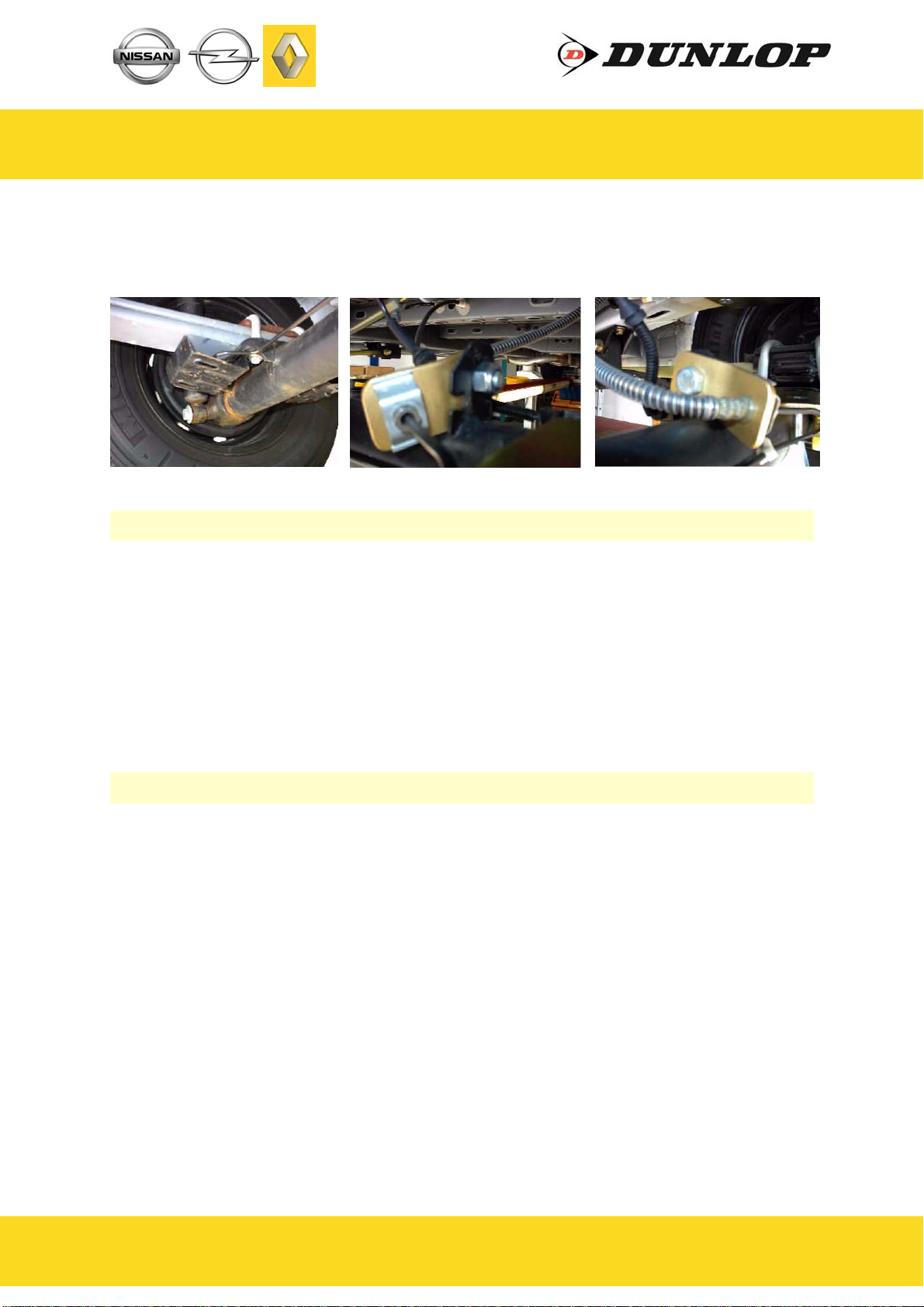
5.1 Preliminary Step - LSV Spring Length Measurement
Vehicles without an antilock braking system have a load sensing valve
fitted. This has a spring linkage as shown by Figure 1. Before beginning
installation, measure and record the length (x) of the linkage between
the chassis and the axle mounting brackets.
5.3 Rerouting brake line
i. Some elderly vehicles have a protection plate below the leaf spring.
The brake line is connected to this plate. Replace it to the other hole
in this plate.
ii. There is a small bracket at you kit to swift the position more to the
rear where the brake hose switches to the brake line. This needs to
be done to give the air bellow enough free space. You need to
disconnect the brake line from the brake hose.
iii. After connecting it to each other again on the mall bracket. It is
needed to bleed the brake line. At your right rear side

L.MAS.MOV.C.M
Nissan Interstar Opel Movano Renault Mastervan
9
DUNLOP and the Flying D Device are trademarks of Dunlop International Group and are used under license by DSC Nederland B.V.
www.dunlopsystems.nl
5.5 Bellow Installation
i. See Section 5.6 - “Tube Connection and Disconnection, Cutting and
Routing” : Connect a tube to the bellow by pushing the tube into the
air inlet port on the underside of the spring and then hand-rotating
the tube by one screw turn. Use black tubing for the left-hand
bellow and blue for the right-hand bellow. Feed the tube through
the large exposed hole in the upper bracket—Figure 8.
ii. Place the bellow into position between the upper and lower brackets
and attach the lower plate of the bellow to the lower bracket using
two M8 x 16mm bolts and two washers—Figures 8 and 9
iii. Attach the top plate to the top plate of the bellow using a single M8
x 20mm bolt and a single M8 serrated washer—Figures 10 and 11
5.4 Fitting of Lower Bracket
i. Rest the lower bracket on the axle directly below the upper plate,
with the two ‘feet’ placed beneath the leaf spring mounting block—
Figure 6
ii. Insert the two M10 x 100mm countersunk bolts into the countersunk
holes in the lower bracket, feed the lower bracket strap up from
below the axle to mate with these bolts, and install the nuts and
washers to secure the lower bracket and strap against the axle—
Figures 6 and 7
iii. After connecting it to each other again on the mall bracket. It is
needed to bleed the brake line at the left side.

L.MAS.MOV.C.M
Nissan Interstar Opel Movano Renault Mastervan
10
DUNLOP and the Flying D Device are trademarks of Dunlop International Group and are used under license by DSC Nederland B.V.
www.dunlopsystems.nl
5.6 Fitting of Inflator Console
OPTION VALVES : Two valves and a small bracket
OPTION 1 : Two valves in a console with two independent
10-bar pressure gauges
OPTION 2 : Two valves in a console with two independent
10-bar pressure gauges and a rocker on/off
switch to operate the electric motor driven air
compressor
OPTION 3 : Four valves (two for raising the vehicle (’UP’)
and two for lowering the vehicle (’DOWN’)) in a
console with two independent 10-bar pressure
gauges. A pressure switch operates the electric
motor driven air compressor to keep the air
reservoir of 1.9-litre at pressure.
Your kit is supplied with one of the inflator options shown above…
OPTION VALVES OPTION 1
OPTION 3OPTION 2

L.MAS.MOV.C.M
Nissan Interstar Opel Movano Renault Mastervan
11
DUNLOP and the Flying D Device are trademarks of Dunlop International Group and are used under license by DSC Nederland B.V.
www.dunlopsystems.nl
Mount the console in a position of your choice whereby it is firmly fixed,
has some protection from the environment (particularly important for the
console with gauges) and is easily accessible. Suggested possible
locations include...
‘Standard’ Console…
on the rear bumper
at the rear beside the license
plate
on the chassis next to a rear
wheel
in a service shutter
(motorhomes)
beside the fuel cap
‘Option 1’, ‘Option 2’ or ‘Option 3’
Console…
in the vehicle cabin, within reach
and sight of the driver
Beside, under the driver seat
in the wall of a cupboard
(motorhomes)
in a service shutter
(motorhomes)
Comfort Package ‘Option 2’
‘Comfort’ Packages
The ‘Option 2’ and ‘Option 3’ panels, as shown above, are each part of a
Comfort Package that is supplied with a compressor (and also an air
reservoir in the case of the ‘Option 3’ panel) for ease of spring inflation
and ride height setting. For further information please ask your dealer.
The picture below shows all of the parts of Comfort Package ‘Option 2’...

L.MAS.MOV.C.M
Nissan Interstar Opel Movano Renault Mastervan
12
DUNLOP and the Flying D Device are trademarks of Dunlop International Group and are used under license by DSC Nederland B.V.
www.dunlopsystems.nl
Cutting
To achieve good sealing and air-tight fitting of tube ends to their
connecting parts, it is very important to cut tubing cleanly and squarely.
A dedicated guillotine action tubing cutter is recommended, or a craft
knife if such a tool is not available. Do not use electrician’s side cutters.
A dedicated tubing cutter -
Recommended Electrician’s Side Cutters
NOT Recommended
Connection and Disconnection
Tubes are connected as shown by the diagrams below...
5.7 Tube Connection and Disconnection, Cutting and Routing
A B C
A. Slide a nut over the end of the tube
B. Push the tube onto the connector as far as possible
C. Feed the nut up to the connector, fully tighten by hand and finally
tighten one additional turn using spanners

L.MAS.MOV.C.M
Nissan Interstar Opel Movano Renault Mastervan
13
DUNLOP and the Flying D Device are trademarks of Dunlop International Group and are used under license by DSC Nederland B.V.
www.dunlopsystems.nl
5.8 Spring Inflation
Once installation of the air assist kit is complete, inflate the springs via
the inflator console taking careful note of the following...
Maximum and Minimum Pressure
Maximum Pressure 7.0bar Minimum Pressure 0.5bar
Do not exceed 7.0bar (101psi), which is the recommended
maximum charge pressure for the air springs.
The springs may be deflated if the vehicle is to be stored for a
lengthy period without use, but a pressure of at least 0.5bar
(7.25psi) should be maintained at all times in order to avoid
possible compression damage to the springs.
Routing
Study the underside of the vehicle and decide how to route each branch
of the air circuit…
To minimise the risk of chafing, avoid running tubing over metal
edges as much as possible
Avoid close proximity to heat sources such as the exhaust assembly
Choose a route that provides as much protection as possible from
dirt, debris and any solid objects that may impact the underside of
the vehicle
It is recommended that tubes are guided alongside brake lines as much
as possible.
Use cable ties (‘tie wraps’) to secure tubing to the chassis, taking
care not to over-tighten them.
5.9 Spring Alignment
Spring out of alignment—
mounting plate axes offset Spring in alignment—
mounting plates parallel
and coaxial
CAUTION!
Before fully tightening the bolts that secure the air spring to the
upper and lower brackets, set the vehicle at ride height (spring
height approximately 14cm) and ensure that the springs are
correctly aligned.

L.MAS.MOV.C.M
Nissan Interstar Opel Movano Renault Mastervan
14
DUNLOP and the Flying D Device are trademarks of Dunlop International Group and are used under license by DSC Nederland B.V.
www.dunlopsystems.nl
5.11 Maintenance
Following installation, it is recommended that all metal parts are coated
with a protective substance such as body wax.
The system does not require very much maintenance other than…
to maintain air pressure in the springs. Much like a tyre, the system
may lose a little air over time.
to keep the air bellows clean. It is suggested that, when washing
the vehicle, the bellows are inspected and cleaned as necessary
(preferably by spraying). Look in particular for stones or grit
5.10 IMPORTANT! Load Sensing Valve (LSV) Adjustment
Once the auxiliary air suspension system is installed and the bellows are
inflated such that the desired vehicle ride height is achieved, the LSV
must be adjusted—see Figure 13. Inflate the springs to a height of
13.5cm, then adjust the length of the spring linkage via the adjustment
collar until the total length between the chassis and axle mounting
brackets is the same as it was before beginning installation (see
‘Preliminary Step’, Section 5.1).
The adjustment collar has a screw that locks the outer part of the linkage
to the inner part when tightened and enables the inner part to slide
inside the outer part when loosened.
A wait of 24 hours is recommended in order to ensure that the
vehicle has maintained its stance and that there are no air leaks
present.
5.12 Check List
Before driving the vehicle following completion of installation of the
auxiliary air suspension system, please check...
...air springs set in alignment (Section 4.9)?
...enough free space around the air springs to avoid wearing?
...all metal parts wax coated (Section 4.11)?
...manufacturer’s declaration form completed and a copy returned?
...all bolts tightened to the recommended torque (Page 8)?
2

L.MAS.MOV.C.M
Nissan Interstar Opel Movano Renault Mastervan
15
DUNLOP and the Flying D Device are trademarks of Dunlop International Group and are used under license by DSC Nederland B.V.
www.dunlopsystems.nl
5.13 Installation Drawings

L.MAS.MOV.C.M
Nissan Interstar Opel Movano Renault Mastervan
16
DUNLOP and the Flying D Device are trademarks of Dunlop International Group and are used under license by DSC Nederland B.V.
www.dunlopsystems.nl
2
3 4
5 6
7 8
1
x

L.MAS.MOV.C.M
Nissan Interstar Opel Movano Renault Mastervan
17
DUNLOP and the Flying D Device are trademarks of Dunlop International Group and are used under license by DSC Nederland B.V.
www.dunlopsystems.nl
109
11 12
13
Spring out of
alignment—mounting
plate axes offset
Spring in alignment—
mounting plates parallel
and coaxial
CAUTION!
Before fully tightening the bolts that secure
the air spring to the upper and lower
brackets, set the vehicle at ride height
(spring height approximately 13.5cm) and
ensure that the springs are correctly aligned.

L.MAS.MOV.C.M
Nissan Interstar Opel Movano Renault Mastervan
18
DUNLOP and the Flying D Device are trademarks of Dunlop International Group and are used under license by DSC Nederland B.V.
www.dunlopsystems.nl
6. EPILOGUE
DSC Nederland hopes that you enjoy the benefits that your DUNLOP air
suspension system will provide for you. To ensure optimal performance,
we advise that you have your system checked frequently by qualified
personnel. As recommended in the fitting instructions, it is important to
coat all the steel parts with a protective substance such as body wax.
IMPORTANT : Manufacturer’s Declaration Form
A manufacturer’s declaration form is provided with your kit.
Following installation of the kit please ensure that this form is
completed, signed by a qualified fitter and a copy is returned to
DSC Nederland by post, fax or e-mail. Our e-mail address is:
As a condition of your warranty, modifications to the system may only be
carried out by personnel of DSC Nederland.
Enquiries
For general enquiries please contact one of our dealers. You can find
them on our website.
www.dunlopsystems.nl


www.dunlopsystems.nl
DUNLOP and the Flying D Device are trademarks of Dunlop International Group and are used under license by DSC Nederland B.V.
DSC Nederland B.V.
Het Wegdam 22
7496 CA Hengevelde
Nederland
Tel. : +31 (0)547 333065
Fax. : +31 (0)547 333068
e-mail: [email protected]
Auxiliary Air Suspension
Table of contents
Other Dunlop Automobile Accessories manuals

Dunlop
Dunlop L.312.C.M User manual

Dunlop
Dunlop L.SPR.18R.C.M User manual

Dunlop
Dunlop L.412.C.M User manual

Dunlop
Dunlop L.CRA.17D.C.M User manual

Dunlop
Dunlop L.NAV.05.C.M User manual

Dunlop
Dunlop L.IVE.65C.C.M User manual

Dunlop
Dunlop L.KI.C2-C4.C.M User manual

Dunlop
Dunlop FILL&GO User manual

Dunlop
Dunlop L.SPR.18D.C.M User manual

Dunlop
Dunlop L.D84.C.M User manual
Popular Automobile Accessories manuals by other brands

Road Armor
Road Armor Vaquero 611VF6B Install instructions

muth
muth Signal installation instructions

Directed
Directed GM10 Firmware Specific Guide

AEROKLAS
AEROKLAS 1400 Series Installation instruction

Fiamma
Fiamma CARAVAN XL A 02093-01A Installation and usage instructions

iDataLink
iDataLink maestro Rr install guide