APT3100SmartPressureTransmitter OperationManualM3100-E01B
5 DUONSystemCo.,Ltd.
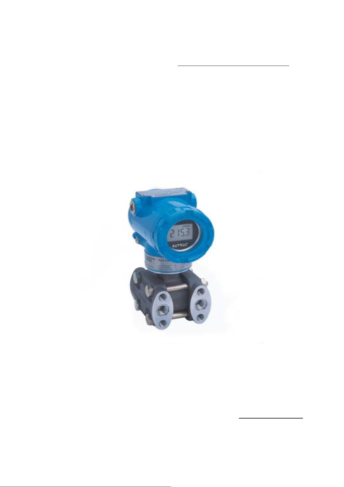
Chapter 1 Introduction
The APT3100 Smart Pressure Transmitter are correctly calibrated at the factory before shipment. To
ensure correct and efficient use of the instrument, please read this manual thoroughly and fully
understand how to operate the instrument before operating it
①The contents of this manual are subject to change without prior notice.
②All rights reserved. No part of this manual may be reproduced in any form without DUON
System’s written permission.
③If any question arises or errors are found, or if any information is missiong from this manual,
please inform the nearest DUON System sales office.
④The specifications covered by this manual are limited to those for the standard type under
the specified model number break-down and do not cover custom-made instrument.
⑤Please note that changes in the specifications, construction, or component parts of the
instrument may not immediatelty be reflected in this manual at the time of change, provided
that postponement of revisions will not cause difficulty to the user from a functional of
performance standpoint.
1.1 Using This Manual
The Chapters in this operating manual provide information on installing, operating, and maintaining
devices from the AUTROL Model APT3100 Samrt Pressure Transmitter. The Chapters are organized as
follows. Chapter 2 Handling Cautions
This chapter consists of core information for installing APT3100 on operating place after
buying it. Chapter 2 provides instructon on commissioning and operating Model APT-3100 Smart
Pressure Transmitters. Informations on software functions, configuration parameters, and on-line
variables is also included.
Chapter 3 Transmitter Functions
Chapter 3 contains in consideration of handling Model APT3100 Smart Pressure Transmitters.
Chapter 4 Installation
Chapter 4 contains mechanical, environment consideration and electrical installation
instructions on the Model APT3100 Smart Pressure Transmitters.
Chapter 5 On-line Operation
Chapter 5 describes the configuration the parameter how to use variety of the Model
APT3100 Smart Pressure Transmitters' software fucntion and configuration. See the following list for
the details.
①Regulations of circuit's Input/Output characteristics; Sensor or Output Trim
②Changed of output characteristic; Range Configuration, Output Type, Damping,Unit
③Changed of general data; Tag No.,Date,Message etc.
Chapter 6 Maintenance