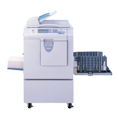
Duplo DP-A100 II User manual


Indicates a medium degree of potential danger. Failure to heed the caution
may lead to injury or damage to property.
<Examples of Pictorial Symbols>
WARNING
CAUTION
Safety Precautions
●Use only the power cord that is provided among the accessories.
Insert the power cord plug firmly into the socket, so that proper electrical contact
is effected.
→Use of any other power cord could result in imperfect grounding.
If grounding is imperfect and electrical leakage occurs, fire or electric shock
could result.
●Do not use a source voltage other than that specified.
Do not connect two or more loads to a single outlet.
→Doing so may result in fire or electric shock.
●Do not place the machine in a humid or dusty area.
→Doing so may result in fire or electric shock.
●Once the machine is in position, secure in place using the caster locks.
→If the machine falls over, this could result in personal injury.
●Do not place the machine in an unstable position, such as on an unsteady
support or sloping area.
→If the machine is dropped or falls over, this could result in personal injury.
●The precautions below are vital for safety and must be taken.
Warning Terminology
The following warning terminology is used in the this installation instructions.
Indicates a high degree of potential danger. Failure to heed the warning
may lead to death or serious injury.
A circle with a line through it indicates a prohibited action.
The particular act prohibited is indicated by a picture inside the circle.
(In the example shown here, the prohibited act is disassembly.)
A black disc indicates an instruction, or sometimes a prohibited action.
The instruction itself is indicated by pictorial symbols drawn in white on the disc.
(In the example shown here, the instruction is Remove the plug from the outlet.)
CAUTION
WARNING

1
Carry out unpacking in a place that is safe
for the work.
1. Unpacking Checks
IMPORTANT
1. Package for 1 complete DUPRINTER:
Printer unit
Model name: DP-A100 /A105 /A120 /
A125
2. Unpack the package.
3. Check the contents.
●Printer unit package
<<DP-A100 /A120 >>
Item Quantity
1 Printer unit 1
2 Installation Manual 1
3 Instruction Manual 1
4 Warranty (USA only) 1
5 Master holder 2
6 Power cord 1
7 Support tray unit 1
●Printer unit package
<<DP-A105 /A125 >>
Item Quantity
1 Printer unit 1
2 Installation Manual 1
3 Instruction Manual 1
4 Master holder 2
5 Power cord 1
6 Support tray unit 1
7 Printer driver CD-ROM 1

2
1. Place the printer unit at the installation site.
2. Remove all the remaining fixing tapes.
3. Loosen the four screws to attach the support
tray unit. Then tighten the screws.
2. Installation
CAUTION
●Lifting of the printer unit should be
performed by two or more persons,
not by one person alone.
Otherwise, hands could get caught
up or crushed.
●Place the printer unit on a flat, level
surface.
Screws
Support tray unit

3
220 VAC model
5. Press the Iside of the power switch.
6. Check the control panel.
●The control panel must display normally.
3. Plug the other end into the outlet.
3. Turning the Power Switch ON
●Connect the DUPRINTER to an
outlet providing a 60 Hz, 15 A power
supply of at least 120 V.
●Insert the power cord’s plug correctly
into the outlet, so that electrical
connection is effected completely.
●Position the DUPRINTER close to
the power outlet. Do not connect
multiple loads to a single outlet.
If an extension cord is necessary:
Extension cord should be of at
least 130 V, 15 A specification,
conforming to standard, and not
exceed 5 m in length.
●The power cord should never be
stepped on, or crushed between
objects. If it is, accidents could
result.
WARNING
●Connect the DUPRINTER to an
outlet providing a 50 Hz, 8 A power
supply of at least 230 V.
●Insert the power cord’s plug
correctly into the outlet, so that
electrical connection is effected
completely.
●Position the DUPRINTER close to
the power outlet. Do not connect
multiple loads to a single outlet.
If an extension cord is necessary:
Extension cord should be of at
least 250 V, 8 A specification,
conforming to standard, and not
exceed 5 m in length.
●The power cord should never be
stepped on, or crushed between
objects. If it is, accidents could
result.
WARNING
Inlet
Power plug
1. Make sure that the power switch is off.
2. Plug the supplied power cord into the inlet
on the DUPRINTER.
4. Make sure that the above steps (2 and 3) are
performed correctly.
120 VAC model

4
1. Take out a new master roll from the bag.
2. Insert the master holders deeply into both
ends of the master roll.
(The holders are interchangeable.)
3. Open the upper cover.
4. Set the master roll in the direction as shown
in the figure below .
5. Peel off and pull out the seal.
(Make sure that the black line is on the
operator’s side.)
6. Pull out the master and insert the edge of the
master in until it comes into contact with the
roller.
4. Setting the Master Roll
Master roll
Upper cover
Master holders
●Do not remove the cover affixed
with Warning Label.
●Personnel may be injured by the
movable cutter inside the machine.
WARNING
Master roll
Seal
Black line

5
7. Push the master set lever
(thermal head
escape lever).
The master will be automatically pulled in.
If the master is not pulled in, gently press it
as far as possible.
●If the master is wrinkled, turn the power
OFF and pull out the master roll, and then
set the master again.
The wrinkle on the master can be removed
by pushing the master set lever (thermal
head escape lever) again while setting the
master.
8. Close the upper cover.
Master set lever
(Thermal head escape lever)
REFERENCE
Upper cover

6
4. Grip the stay at the upper part of the drum
with your other hand, and pull out the drum
unit toward you while slightly lifting near end
of the drum.
1. Press and hold the JOG switch until the
drum comes to a stop with a beep.
2. Open the front cover.
3. Lift up the lever. While lifting it up, pull out
the drum handle straight toward you until it
stops.
5. Preparing the Drum
JOG Switch
Front cover
Lever
Drum handle
Lever
Master clamp
●Do not touch the drum or rollers
when you operate the JOG switch.
●Do not put your hands or fingers
inside the machine while it is
operating.
Your hands could be caught up or
crushed, resulting in injury.
WARNING
●Hold the drum unit level with both
hands.
●Do not press the surface of the
drum unit or scratch it with your
fingers.
●Before you place the drum unit
down, make sure that the place
you are placing it is free of any
objects and is a flat, solid surface.
WARNING
5. Move the lever with a hand once or twice to
open and close the master clamp.
Stay

7
6. Hold the drum unit level and place the drum
guide roller onto the rail in the machine.
7. Release the stay at the upper part of the
drum and push the drum unit in about 10
cm while lifting up the front end slightly.
8. Hold the drum unit level and push it in
gently until it comes to a stop.
9. Lift the lever toward you while pushing the
drum in.
10. Lower the lever until it comes to a stop.
11. Close the front cover.
Lever
Lever
Front cover
Drum guide
roller
Rail

8
5. Push the ink pack in to the set line on the
ink pack.
6. Push the ink pack holder back.
7. Close the front cover.
1. Open the front cover.
2. Grasp the ink pack holder and pull it down.
3. Remove the cap from a new ink pack.
4. Insert the ink pack so that the groove on the
lip fits onto the Ugroove of the holder.
6. Setting the Ink Pack
Ink pack
Front cover
Ugroove of holder
Front cover
Set line
CAUTION
●Do not leave an ink pack uncapped
for longer than necessary.
Ink pack holder
Correct Incorrect
Ink pack holder
This manual suits for next models
3
Other Duplo Disc Duplicator manuals
Popular Disc Duplicator manuals by other brands
Kanguru
Kanguru U2-DVDDUPE-S user guide
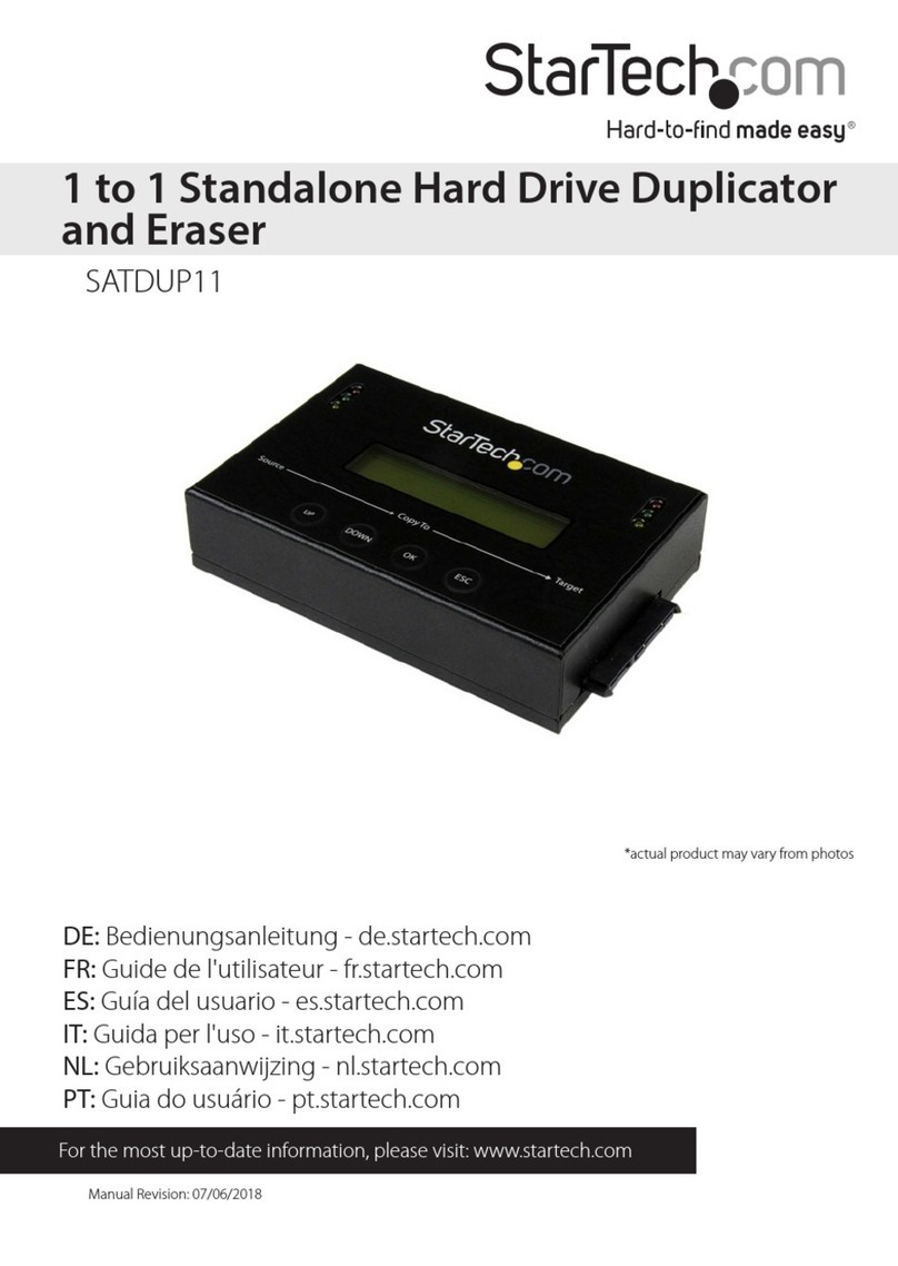
StarTech.com
StarTech.com 8STSATDUP11 manual
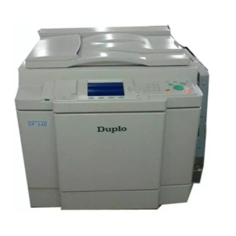
DUPLO SEIKO CORPORATION
DUPLO SEIKO CORPORATION Duprinter DP-460 Service manual
Addonics Technologies
Addonics Technologies UDFH7 user guide
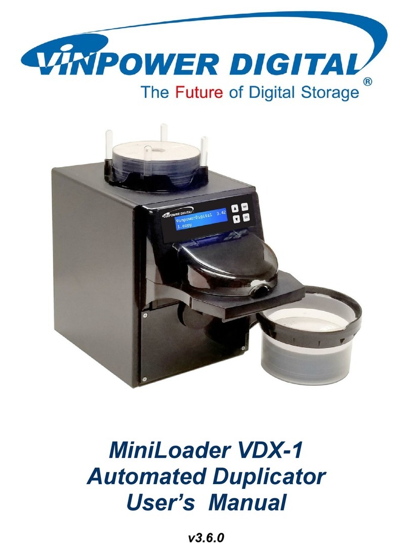
Vinpower Digital
Vinpower Digital MiniLoader VDX-1 user manual
Addonics Technologies
Addonics Technologies CFASTD5 user guide
