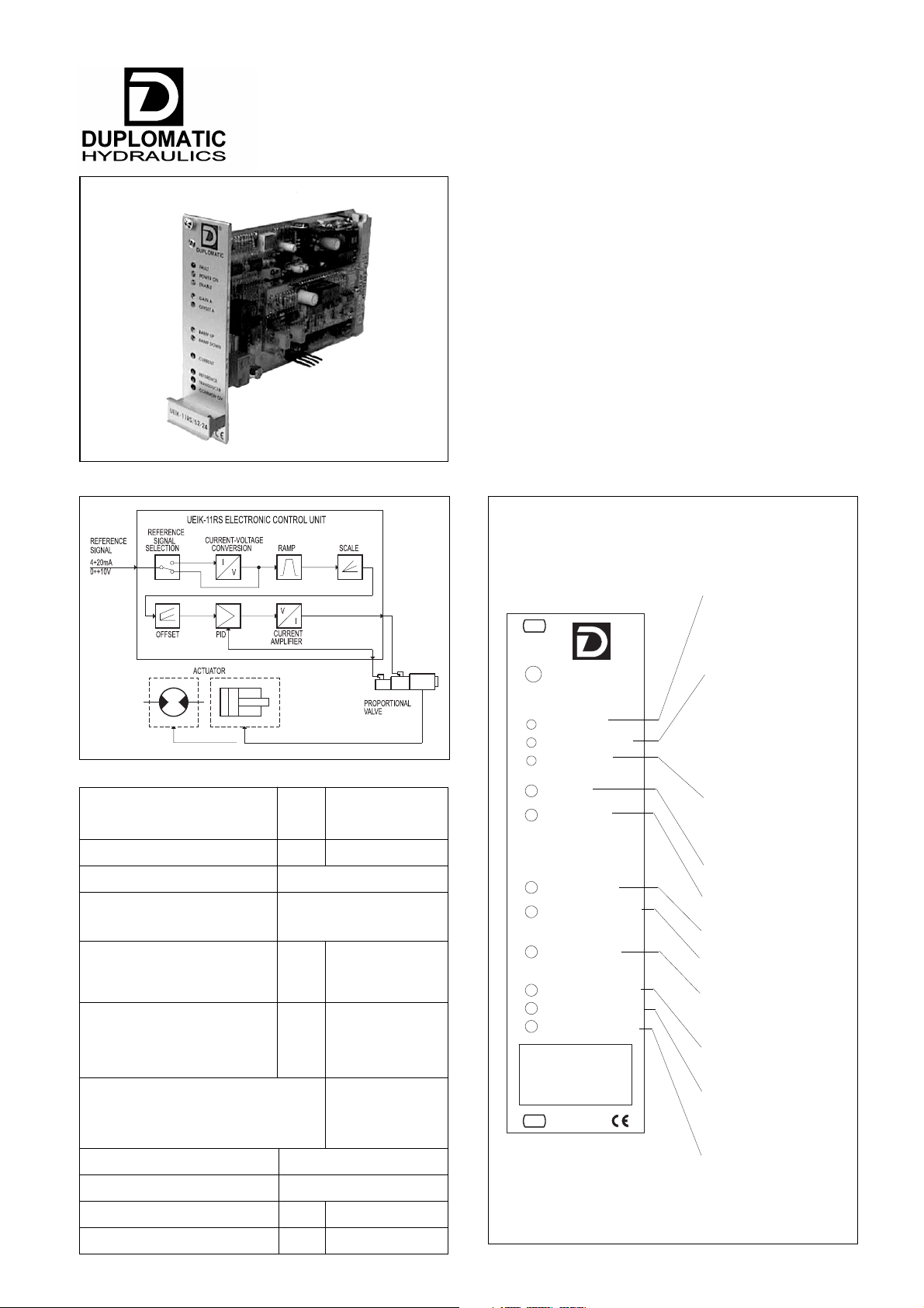
manuals.online logo
Brands
  1. Home
  2. •
  3. Brands
  4. •
  5. Duplomatic
  6. •
  7. Control Unit
  8. •
  9. Duplomatic UEIK-11RS Series User manual

Duplomatic UEIK-11RS Series User manual

GAIN
FAULT
OFFSET
POWER ON
ENABLE
MADE IN ITALY
COMMON 0V
REFERENCE
RAMP DOWN
CURRENT
RAMP UP
TRANSDUCER
UEIK-11RS*/52-24
DUPLOMATIC
0,20
Eurocard 100x160x35
V DC 22 ÷ 30
Ripple included
kg
DIN 41612-D 32 Male
– overload
– polarity inversion
UEIK-11RS*
ELECTRONIC CONTROL UNIT
FOR SINGLE SOLENOID
PROPORTIONAL VALVE
WITH POSITION FEEDBACK
SERIES 52
FUNCTIONAL BLOCK DIAGRAM FRONT PANEL
TECHNICAL CHARACTERISTICS
24 V DC POWER
SUPPLY
YELLOW LED
– On: normal operation
– Off: card disconnected,
faulty power supply to
card or fuse blown
FAULT SIGNAL
RED LED
– Off: normal operation
– On: transducer fault
CARD ENABLE
GREEN LED
– On: disabled
– On: enabled
Scale factor regulation
Offset current regulation
Ramp up regulation
Ramp down regulation
Reference signal
measurement point
Transducer signal
measurement point
(0 / -5V)
Common zero
Solenoid current
measurement point
(1V=1A)
Power supply
Card size
Connector edge
Operating temperature range °C 0 ÷ 50
Mass
Reference signal:
– Voltage
– Current
V
mA
0 ÷ +10
4 ÷20
KΩ
Ω
10
250
Input reference signal
impedance:
– Voltage
– Current
Power supply electrical
protections
Required power
Output current
W20 ÷ 45
see par. 3.4
89 315/107 ED 1/4
89 315/107 ED
Electromagnetic compatibility (EMC)
- EMISSIONS EN 50081-1
- IMMUNITY EN 50082-1
(see par. 5 - NOTE 1)
in compliance with
89/336 EEC
EUROCARD TYPE
The red LED indicates operation of the position transducer:
OFF - normal operation
ON - transducer fault or electrical connection failure. In this case
the current supply to the solenoid is shut off and the valve is set at
the rest position, the ENABLE LED switches off and the OK card
relay contact opens (6a - 6c pin)
1 - IDENTIFICATION CODE
UEIK-11RS*
SERIES 52
Power supply voltage = 24 V DC
Series No. (from 50 to 59 sizes and
mounting dimensions remain unchanged)
Eurocard type electronic
control unit
For single solenoid proportional valves
Position feedback control
3.1 - FAULT
89 315/107 ED 2/4
U E I K - 11 R S / 52 -24
3.4 - GAIN (Scale factor regulation)
The “GAIN” potentiometer enables regulation of the relation between
the set reference value and maximum current supplied to the
solenoid and therefore the hydraulic parameter controlled by the
valve.
The maximum current of the card is limited to 1A for RSQ version
and to 1,8A for RSD version. See par. 6 for default values.
Rotate clockwise to increase current.
2 - FUNCTIONAL SPECIFICATIONS
The card requires a power supply of 22-30 V DC and 20 ÷ 45 W
(pin 2a/2c - 4a/4c).
Power supply voltage must be rectified and filtered, with maximum
admissible ripple within the above voltage range.
2.3 - Reference signal
The card accepts voltage reference signals (0 ÷ +10V) or current
signals (4÷20 mA).
N.B: If the signal is transmitted by potentiometer, please verify
that this has a load of at least 200 Ω.
See par. 9 for electrical connections.
The diagram shows characteristics of valve spool position
according to the reference signal.
3 - SIGNALS AND ADJUSTMENT
The yellow LED indicates card power supply:
ON - normal power supply
OFF - no power supply, faulty power supply or blown fuse
3.5 - OFFSET (Offset current regulation)
The “OFFSET” potentiometer enables regulation of the offset
current of the valve. It is used to eliminate the insensitivity zone
(dead zone) of the valve.
The regulation field is from 0 to 0,5A for RSQ version and from 0 to
0,9A for RSD version.
The offset current is activated when the reference signal exceeds
the threshold of + 150 mV (or 4,25 mA).
The offset is not active and only the polarization current equal to 25
mA is present beneath this threshold.
NOTE: The variation of the set value of the offset current causes a
corresponding variation of the scale factor value.
Rotate clockwise to increase current.
The UEIK-11RS*/52 card is an electronic control unit Eurocard type
for closed loop control of single solenoid proportional valves with
positional feedback control.
The card controls the position of the valve spool according to the
reference input signal enabling linear regulation and reduced
hysteresis.
The front panel is fitted with LEDs to indicate card functions and
potentiometers to optimise control.
3.3 - ENABLE
2.2 - Electrical protection
The card is protected against overvoltage and polarity inversion.
A 3,15A fast-acting fuse is fitted for power circuit protection.
2.1 - Electric power supply
3.2 - POWER ON
From 22 to 30 V DC (pin 24c) enable command is required for card
operation.
The condition of the card enable is shown by both a visible LED on the
front panel and as a contact available for the user on pins 6a and 6c.
The green LED indicates:
ON - card enabled
OFF - card disabled
Q: version for flow contrl valves type RPCER1/52
D: version for directional valves type DSE3F-S*
UEIK-11RS*
SERIES 52
Enables voltage reading of the valve spool position (0 / -5V).
4.3 - TRANSDUCER (Transducer signal measurement point)
89 315/107 ED 3/4
Enables reading of reference signal sent to the card.
Reading is direct, but of opposite sign, with voltage reference while
current conversion is: 4 mA = 0V 20 mA = -10V.
4 - SIGNAL MEASUREMENT
4.1 - CURRENT (Solenoid current measurement point)
Enables voltage reading of current supplied to the solenoid.
Reading conversion: 1V DC = 1A.
4.2 - REFERENCE (Reference signal measurement point)
The electronic control unit is supplied factory-set. Standard settings are:
– “GAIN” regulation: +10V (or 20 mA) reference signal
corresponding to maximum valve opening (transducer = -5V).
In open loop “GAIN” regulation corresponds to a current supply of
1 A for RSQ version and 1,8 A for RSD version, to the solenoid
with maximum reference signal.
– “OFFSET” regulation: zero
– “RAMP UP” and “RAMP DOWN” regulation: minimum
– position SW1 on V
– position SW2 on S
– position SW3 on AC
– position S1 on N
– switching frequency (PWM) = 230 Hz
7 - START-UP AND CONTROL SETTINGS
If required, settings can be adjusted as follows:
a) OFFSET CURRENT REGULATION
– Set “GAIN” potentiometer to minimum.
– Enter reference signal at maximum value (+10V or 20 mA).
– Set the “OFFSET” potentiometer so that the valve is
positioned at the start of the work zone.
6 - DEFAULT CONDITIONS
5 - INSTALLATION
The card is designed for assembly on a rack or a card holder with
interface for connector types DIN 41612 - size D - 32 pole.
It is recommended to use cable sections of 1 to 2,5 mm2, depending
on their length, for power supply and solenoid connections. For
other connections it is recommended to use cables with a screened
sheath connected to earth only on the card side.
NOTE 1:To observe EMC requirements it is important that the control
unit electrical connection is in strict compliance with the wiring diagram of
par. 9.
As a general rule, the valve and the electronic unit connection wires
must be kept as far as possible from interference sources (e.g.
power wires, electric motors, inverters and electrical switches).
In environments that are critical from the electromagnetic interference
point of view, a complete protection of the connection wires can be
requested.
The overall and mounting dimension diagram in par. 10 shows four
switch banks: SW 1 - SW 2 - SW 3 and S1 which enable the card
to be set up as required.
NB. Each modification to switch settings must be carried out
with the card disconnected from the power supply. The
individual switches inside each bank must all be set in the
same position.
SELECTION OF VOLTAGE OR CURRENT REFERENCE SIGNAL
(SW 1 bank comprising three individual switches)
– select V for voltage signal
– select I for current signaI.
SELECTION OF SINGLE ENDED OR DIFFERENTIAL REFERENCE
SIGNAL
(SW 2 bank comprising one individual switch)
– select S for single ended reference signal. This condition is
obligatory in the case where the reference signal is generated
with an external potentiometer fed by the card itself.
– select D for differential reference signal. This condition is
preferable in the case where the reference signal comes from a
PLC or CNC analogic outlet.
OPEN OR CLOSED LOOP SELECTION
(SW 3 bank comprising two individual switches)
– select AC for closed loop
– select AA for open loop.
TRANSDUCER POLARITY SELECTION
(SW 1 bank comprising one individual switch)
– select N for direct operated valve types DSE3F - RPCER1/52
– select D for piloted valves.
NB. In the event of transducer malfunction, AA can be selected
to proceed with open loop operation. In this case, the ENABLE
LED illuminates and the OK relay card contacts close and the
FAULT LED remains lit to indicate alarm status.
SWITCHING FREQUENCY ADJUSTMENT
It is possible to change the switching frequency (PWM) by acting on
the trimmer PT7 (see par. 10).
The setting range is from 80 to 1600 Hz.
An appropriate switching frequency adjustment allows reduction of
the valve hysterisis value.
Clockwise rotation to increase the frequency.
8 - CARD CIRCUIT SETTINGS
b) SCALE FACTOR REGULATION
– Enter the reference signal at maximum value (+10V or 20 mA).
– Set “GAIN” potentiometer so that the controlled hydraulic
parameter reaches the maximum required value.
c) RAMP REGULATION
– Regulate the “RAMP UP” and “RAMP DOWN” potentiometers
to obtain the gradual valve operation required with a reference
signal variation.
3.6 - RAMP UP / RAMP DOWN (Ramp regulation)
“RAMP UP” and “RAMP DOWN” potentiometers, in a range from 0,03
to 7 sec., regulates the time required to achieve the supplied current
according to a step change of the reference signal up or down.
It is possible, in this way, to control the valve response time, adjusting
it to the requirements of the hydraulic circuit and the machine cycle.
Ramps can be inhibited by transmitting a 22 to 30 V DC exclusion
command to pin 16a. In this case, the ramp residual time is 10 ms.
Rotate clockwise to increase ramp time.
GAIN
FAULT
3,15A-RAP
FUSE
OFFSET
POWER ON
ENABLE
129
100 (3HE)
835
(7TE)
MADE IN ITALY
COMMON 0V
REFERENCE
RAMP DOWN
CURRENT
RAMP UP
TRANSDUCER
UEIK-11RS*/52-24
D
AC
AA
S
V
SW1
FAULT
POWER ON
ENABLE
GAIN
OFFSET
N
T.ZERO
D
T.GAIN
160
RAMP UP
RAMP DOWN
CURRENT
REFERENCE
COMMON 0V
TRANSDUCER
14
S1
SW3
SW2
I
PT7
switching frequency
test point
(positive)
connect the probe
negative
to the COMMON 0V
DUPLOMATIC
x 0.05A
+10V
+V
-V
ENABLE
+V
0V
-V
FAULT
6a
6c
26a
26c
28a
current
amplifier
green
led
PID PWM
GAIN
OK card
red led
FUNCTION
10a +10V
CORRECT
CLOSE =
max load I=0.25A
EV
2
3
1
TRS
28c
Gain
24a
8c
22c
LVDT input
23V
0V
Zero
default
D
N
feedback
T.P. CURRENT 1V=1A
current
yellow
led
POWER ON
fuse
3,15A-RAP
2a
2c
4c
8a
4a
T.P. COMMON 0V
Up
DU
Down
24c
16a
enable
ramp by pass
V
default
12a
12c
22÷30VDCX20÷45W
0 VDC
±10% RIPPLE INCLUDED
GND
CLOSE TO
ENABLE
RAMP INHIBIT
CLOSE TO
REFERENCE SIGNAL
AC
default
default
selection
type
reference
selection of single
ended or differential
reference
12a
12c
12a
I
4ac
10a
12c
12a
V
V
12c
REFERENCE SIGNAL
CURRENT
VOLTAGE
POTENTIOMETER
10K TYPICAL
4ac
4÷20mA
0÷10V
0÷10V
RAMP AA
SD
T.P. REFERENCE
OFFSET
T.P.TRANSDUCER
Transducer and
fault processing
I
9 - CARD CIRCUIT AND WIRING DIAGRAMS
10 - OVERALL AND MOUNTING DIMENSIONS
UEIK-11RS*
SERIES 52
89 315/107 ED 4/4
REPRODUCTION IS FORBIDDEN. THE COMPANY RESERVES THE RIGHT TO APPLY ANY MODIFICATIONS.
DUPLOMATIC OLEODINAMICA SpA
20025 LEGNANO (MI) - P.le Bozzi, 1 / Via Edison
Tel. 0331/472236 - Fax 0331/548328

Other Duplomatic Control Unit manuals

Duplomatic EPC 10 Series User manual

Duplomatic

Duplomatic EPC 10 Series User manual

Duplomatic DDC1-12-H Series User manual

Duplomatic

Duplomatic DDC1-12-H Series User manual

Duplomatic DDC4-15-400/20 User manual

Duplomatic

Duplomatic DDC4-15-400/20 User manual

Popular Control Unit manuals by other brands

BRP EVINRUDE ICON Series instructions

BRP

BRP EVINRUDE ICON Series instructions

Milton Roy H Series instruction manual

Milton Roy

Milton Roy H Series instruction manual

Pilz PNOZ ms4p operating manual

Pilz

Pilz PNOZ ms4p operating manual

Walther Systemtechnik S11 series Assembly instructions

Walther Systemtechnik

Walther Systemtechnik S11 series Assembly instructions

Siemens SIMATIC FM 353 manual

Siemens

Siemens SIMATIC FM 353 manual

Galvin Specialised CliniMix Lead Safe TMV SS Product installation guideline

Galvin Specialised

Galvin Specialised CliniMix Lead Safe TMV SS Product installation guideline

Toshiba TC Series manual

Toshiba

Toshiba TC Series manual

MSA AutoMaXX-ASE quick start guide

MSA

MSA AutoMaXX-ASE quick start guide

Zamel exta EW-01 instruction manual

Zamel

Zamel exta EW-01 instruction manual

FM Mattsson FMM 4285 Instruction

FM Mattsson

FM Mattsson FMM 4285 Instruction

Keyscan CA150 installation guide

Keyscan

Keyscan CA150 installation guide

EVERSPRING AN144 manual

EVERSPRING

EVERSPRING AN144 manual

TeeJet BoomPilot installation manual

TeeJet

TeeJet BoomPilot installation manual

Festo VZQA-C-M22C-6-GG-V2V4E-2 Instructions & Operating

Festo

Festo VZQA-C-M22C-6-GG-V2V4E-2 Instructions & Operating

DKS 6004 owner's manual

DKS

DKS 6004 owner's manual

StarTech.com BOX4MODULE quick start guide

StarTech.com

StarTech.com BOX4MODULE quick start guide

Texas Instruments TPS53515 user guide

Texas Instruments

Texas Instruments TPS53515 user guide

Tecomat IC-7702 Basic documentation

Tecomat

Tecomat IC-7702 Basic documentation

manuals.online logo
manuals.online logoBrands
  • About & Mission
  • Contact us
  • Privacy Policy
  • Terms and Conditions

Copyright 2025 Manuals.Online. All Rights Reserved.