Durapac DPA-18 User manual

ABSOLUTE EQUIPMENT PTY LTD –2/186 Granite Street, GEEBUNG QLD 4034 –Australia
sales@absoluteequipment.com.au –Phone: +61 7 3865 4006 –Fax: +61 7 3102 6288
Maximum Operating Pressure –700 bar
Instruction Manual
Reciprocating Air Hydraulic Power Unit
Model –DPA-18

Instruction Manual
DPA-18 Air Hyd. Power Unit - V1.0 www.durapac.com Page 2 of 11
This is a safety alert symbol. It is used to alert you to potential personal injury hazards.
Obey all safety messages that follow this symbol to avoid injury or death
1.0 Product Information
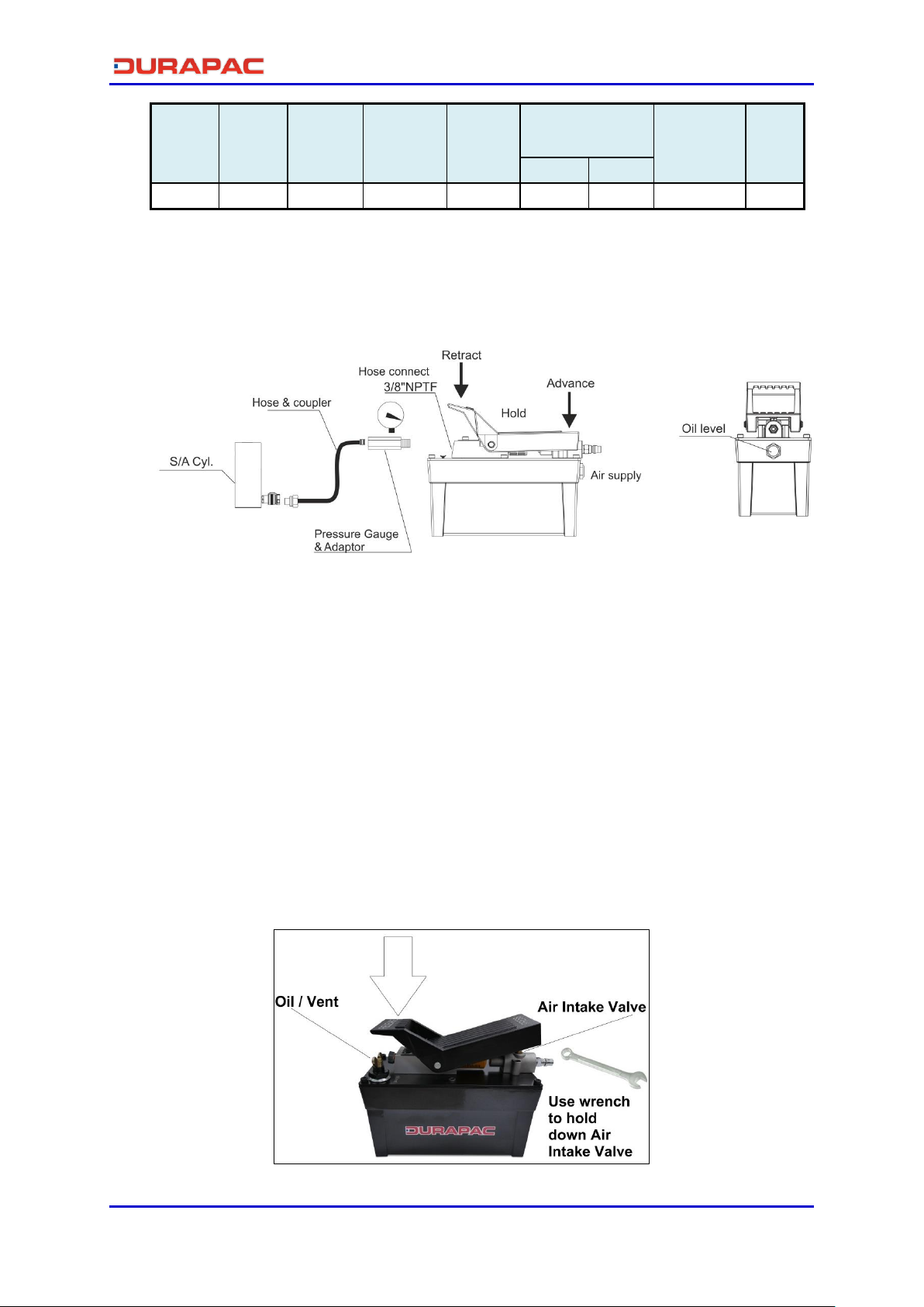
DURAPAC –Reciprocating Air Hydraulic Power Units are engineered to meet Industrial Standards for
Performance and Safety. The DPA-18 model’s unique hydraulic circuit allows the quick displacement
of hydraulic fluid under no load conditions and easy pumping in loaded conditions. These air
actuated power units supply compressed hydraulic fluid to compatible applications i.e. cylinder,
presses, spreaders, compactors and crimping machines, anywhere that 700 bar of fluid pressure is
needed.
1.8 L usable oil reservoir
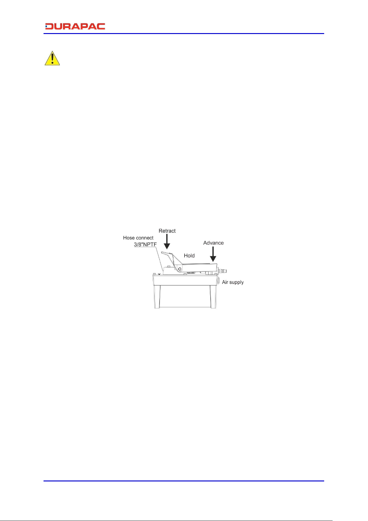
3 position treadle for adv/hold/retract functions
Treadle may be operated by hand or foot for greater versatility
Release detent function enhances productivity
Convenient carry handle included
Recommended air pressure range 4-12 bar
Special skill, knowledge and training may be required for a specific task and the product may not be
suitable for all jobs. The user must ultimately make the decision regarding suitability of the product
for any given task and assume the responsibility of safety for all in the work area. Contact a Durapac
representative if you are unsure of your power unit’s suitability for a particular application.
2.0 Receiving Instructions
It is recommended prior to use that an inspection be done by qualified personnel and that any
missing or damaged parts, decals, warning/safety labels or signs are replaced with Durapac
authorised replacement parts only. Any power unit that appears to be damaged in any way, is worn,
leaking or operates abnormally should be removed from service immediately until such time as
repairs can be made. Any power unit that has been or suspected to have been subject to a shock
load should be removed from service immediately until inspected by a Durapac authorised service
centre. Owners and operators of this equipment should be aware that the use and subsequent
repair of this equipment may require specialised training and knowledge.
3.0 Safety
Save these instructions. For your safety, read and understand the information contained within. The
owner and operator should have an understanding of this product and safe operating procedures
before attempting to use this product. Instructions and safety information should be conveyed in the
operator's native language before use of this product is authorised. Make certain that the operator
thoroughly understands the inherent dangers associated with the use and misuse of the product. If
any doubt exists as to the safe and proper use of this product as outlined in this factory authorised
manual, remove from service immediately.
DANGER:
To avoid personal injury keep hands and feet away from work area during operation
Do NOT handle pressurised hoses. Escaping oil under pressure can penetrate the skin

Instruction Manual
DPA-18 Air Hyd. Power Unit - V1.0 www.durapac.com Page 3 of 11
causing serious injury. If oil is injected under the skin, see a doctor immediately
Stay clear of loads supported by hydraulics. A cylinder, when used as a load lifting
device, should never be used as a load holding device. After the load has been raised
or lowered, it must always be supported mechanically
WARNING:
The system operating pressure must not exceed the pressure rating of the lowest
rated component in the system. Install pressure gauges in the system to monitor
operating pressure. It is your window to what is happening in the system
Always wear appropriate personal protective equipment (PPE) when operating
hydraulic equipment. The operator must take precaution against injury due to failure
of the tool or work piece(s)
Do NOT hold or stand directly in line with any hydraulic connections while pressurising
Do NOT attempt to disconnect hydraulic connections under pressure. Release all line
pressure before disconnecting hoses
All personnel must be clear before lowering load or depressurising the system
Do NOT attempt to lift a load weighing more than the capacity of the cylinder
IMPORTANT:
If at any stage, the safety related decals become hard to read, these must be replaced
Minimum age of the operator must be 18 years. The operator must have read and
understood all instructions, safety issues, cautions and warnings before starting to
operate the equipment. The operator is responsible for this activity towards other
persons
Do NOT lift hydraulic equipment by the hoses or couplers. Use the carrying handle or
other means of safe transport
Hydraulic equipment must only be serviced by a qualified hydraulic technician. For
repair service, contact the Durapac authorised service centre in your area. To protect
your warranty, use only high quality hydraulic oil
CAUTION:
KEEP HYDRAULIC EQUIPMENT AWAY FROM FLAMES AND HEAT. Hydraulic fluid can
ignite and burn. Excessive heat will soften packings and seals, resulting in fluid leaks.
Heat also weakens hose materials and packings. For optimum performance do not
expose equipment to temperatures of 65°C (150°F) or higher. Protect all equipment
from weld spatter
No alteration should be made to this device
3.1 Hydraulic Power Units
Do use a gauge or other load measuring instrument to verify load
Do NOT exceed the rated capacity of the power unit or any equipment in the system.
Burst hazard exists if connection pressure exceeds rated pressure
Do NOT operate the system with bent or damaged couplers or damaged threads

Instruction Manual
DPA-18 Air Hyd. Power Unit - V1.0 www.durapac.com Page 4 of 11
Do NOT subject the power unit and its components to shock loads
Use only Durapac approved accessories and components
Do NOT connect to an application which can return more oil to the reservoir than the
power unit reservoir can hold
Do NOT connect the power unit to a hydraulic system that is powered by another
pump
3.2 Hydraulic Hoses & Fluid Transmission Lines
Avoid short runs of straight line tubing. Straight line runs do not provide for expansion
and contraction due to pressure and/or temperature changes
Reduce stress in tube lines. Long tubing runs should be supported by brackets or clips.
Before operating the power unit, connections should be tightened securely and leak-
free. Over tightening can cause premature thread failure or high pressure fittings to
burst
Should a hydraulic hose ever rupture, burst or need to be disconnected, immediately
shut off the power unit and release all pressure. Never attempt to grasp a leaking
pressurised hose with your hands. The force of escaping hydraulic fluid can inflict
injury
Do NOT subject the hose to potential hazard such as fire, sharp objects, extreme heat
or cold or heavy impact
Do NOT allow the hose to kink, twist, curl, crush, cut or bend so tightly that the fluid
flow within the hose is blocked or reduced. Periodically inspect the hose for wear
Hose material and coupler seals must be compatible with the hydraulic fluid used.
Hoses also must not come in contact with corrosive materials such as battery acid,
creosote-impregnated objects and wet paint. Never paint a coupler or hose
FAILURE TO HEED THESE WARNINGS MAY RESULT IN PERSONAL INJURY AS WELL AS PROPERTY DAMAGE.
4.0 Installation
IMPORTANT:
Always secure threaded port connections with high grade, non-hardening pipe thread
sealant. Teflon tape can be used if only one layer of tape is used and it is applied
carefully, two threads back, to prevent the tape from being introduced into hydraulic
system, which could cause jamming of precision-fit parts
To extend the life of your power unit, the air compressor should have a filter, regulator
and lubricator system that will provide clean, lubricated air to the power unit. Contact
a Durapac representative for the necessary accessories
4.1 Familiarise yourself with the specifications and illustrations in this owner’s manual.
Know your power unit, its limitations and how it operates before attempting to use.
Refer to the specification chart below or if in doubt, contact a Durapac representative.

Instruction Manual
DPA-18 Air Hyd. Power Unit - V1.0 www.durapac.com Page 5 of 11
4.2 Air Connection - Remove plastic cap, connect suitable air supply to air input port. Air
input port is designed to fit the popular 1/4" NPT air nipple (not included). Ensure that
your air source can dedicate 7.8 cfm @ 4-12 bar/60-175 psi to each power unit being
operated.
Figure 1 - DPA-18
4.3 Check all system fittings and connections to be sure they are tight and leak free.
4.4 Check oil level in reservoir before operating the power unit.
4.5 Remove air from the power unit –Air can accumulate in the hydraulic system during
the initial setup or after prolonged use, causing the cylinder to respond slowly or in an
unstable manner. Should removal of air from power unit be required, please follow the
steps in 6.2 –Bleeding Air from the System in the Maintenance Section.
4.6 Priming the Pump - Press the retract end of the pedal while holding down the air intake
valve with a hexagonal wrench. The air intake valve is located directly under the pedal.
Allow the pump to cycle approximately 15 seconds. Remove the wrench and press the
advance end of the pedal. If the cylinder extends or pressure builds, the pump has been
successfully primed. If the pump does not respond, repeat the procedure, jogging the
intake valve while holding the pedal in the retract position.
Figure 2 –Priming the Pump
No load Load
DPA-18 S/A
3/8"-NPTF
1,800 700 1,240 160 4-12 8.2
Model
Number
Used
with
Cylinder
Weight
(kg)
Output Flow Rate
(cm3/min)
Air
Pressure
Range (bar)
Usable Oil
Capacity
(cc)
Oil Port
Thread
Pressure
Rating
(bar)

Instruction Manual
DPA-18 Air Hyd. Power Unit - V1.0 www.durapac.com Page 6 of 11
5.0 Operation
IMPORTANT:
Always monitor pressure, load or position using suitable equipment. Pressure may be
monitored by means of an optional manifold and gauge. Load may be monitored by
means of a load cell and digital indicator. Correct application position can only be
determined by the operator of the equipment
Do NOT operate a power unit that is disconnected from the application. If operated in
this condition, the hose and connections will become pressurised. This increases the
chance of a burst hazard. Damage may also occur to the power unit and its
components
5.1 Pump without an Air Regulator
5.1.1 To extend the cylinder, depress the “Advance” end of the pedal until desired
pressure, load or position is reached.
5.1.2 To hold the cylinder in position, release the “Advance” end of the pedal to
deactivate the power unit.
5.1.3 To retract the cylinder, depress the “Retract” end of the pedal.
Figure 3 –Operation
5.2 Pump with an Air Regulator
5.2.1 Open the air shut-off valve or connect the air quick coupler. Note - Under
certain circumstances the pump may need to be primed before operation. Refer
to 4.7 - Priming the Pump in the Installation Section.
5.2.2 Slowly turn the air regulator control on the unit; clockwise to increase pressure,
counter-clockwise to decrease pressure. As air enters the pump, it will begin to
deliver fluid to the system.
5.2.3 Continue to slowly turn the air regulator control clockwise until the unit gauge
reaches the maximum hydraulic pressure rating. A maximum hydraulic pressure
reading should be obtained if air pressure is approximately 10 bar.
5.2.4 Shut off and disconnect the air supply to the pump to release all system
pressure. Check fluid level when the hydraulic system is retracted.
5.2.5 The pump is now ready for operation.

Instruction Manual
DPA-18 Air Hyd. Power Unit - V1.0 www.durapac.com Page 7 of 11
6.0 Maintenance
IMPORTANT:
Check oil level regularly
Use only good quality hydraulic fluid. Do NOT use brake fluid, transmission fluid,
turbine oil, motor oil, alcohol, glycerine etc. Use of anything other than good quality
hydraulic oil will void warranty and damage the power unit, hose, and application. We
recommend Durapac Hydraulic Oil or equivalent
Equipment must only be serviced by a qualified hydraulic technician. For repair service,
contact your local Durapac authorised service centre
Damage to hydraulic hoses may not be detected during visual inspections. For this
reason, Durapac recommends that hydraulic hoses be replaced on a regular basis
Tighten connections as needed. Use non-hardening pipe thread compound when
servicing connections
Dirt, sand, etc. will quickly ruin any hydraulic system. Ensure that couplings are clean and free of
foreign matter. After each use, clean couplings and attach dust caps.
Maintenance is required when wear or leakage is noticed. Periodically inspect all components to
detect any problem that may require service and maintenance.
6.1 Adding Hydraulic Fluid
WARNING: Always add oil with pump fully retracted or the system will contain more oil
than the reservoir can hold
6.1.1 Depressurise and disconnect hydraulic hose from application/cylinder.
6.1.2 With the power unit in its upright, horizontal position, remove the air vent plug
located on top of the reservoir.
6.1.3 Use a small funnel to fill the reservoir to within 12.7 mm (0.5 ") from the
oil/vent cap.
6.1.4 Bleed air from system if necessary.
6.1.5 Wipe up any spilled fluid and reinstall the air vent plug/reservoir cap.
6.2 Bleeding Air from the System
6.2.1 Repeat Steps 6.1.1 to 6.1.3 (above), if required.
6.2.2 Invert cylinder and place at a lower level than the power unit reservoir.
6.2.3 Extend and retract the cylinder several times without putting a load on the
system. Air will be released into the power unit reservoir.
6.2.4 Recheck oil level after removing air.
6.3 Changing Hydraulic Fluid
For best results, change fluid once a year or every 300 hours of use
6.3.1 Repeat Steps 6.1.1 to 6.1.2 (above).

Instruction Manual
DPA-18 Air Hyd. Power Unit - V1.0 www.durapac.com Page 8 of 11
6.3.2 Pour used fluid into a sealable container.
6.3.3 Repeat Steps 6.1.3 to 6.1.5 (above).
6.3.4 Dispose of fluid in accordance with local regulations.
6.4 Lubrication
When power unit is operated on a daily basis, it is recommended that an inline oiler
and air dryer is installed and SAE grade oil (5W to 30W) is used. Set the unit to feed
approximately one drop of oil per minute into the system.
6.5 Storage
6.5.1 When not in use, depressurise and disconnect the hydraulic power unit from
the application.
6.5.2 Wipe clean thoroughly and store in a clean, dry environment. Avoid
temperature extremes.
6.5.3 For transportation or long storage, replace the air vent plug with shipping plug.
6.5.4 Shield power unit with a protective cover.

Instruction Manual
DPA-18 Air Hyd. Power Unit - V1.0 www.durapac.com Page 9 of 11
7.0 Troubleshooting
Problem
Cause
Solution
Application does not extend,
move or respond to
pressurised fluid
Overload condition
Remedy overload condition
Loose couplers
Tighten couplers
Faulty couplers
Replace couplers
Malfunctioning power unit
Contact a Durapac authorised
service centre
Repair or replace as necessary
Inadequate air supply
Ensure air source can dedicate
7.8 cfm @ 4-12 bar/60-175 psi
Pump not primed
Prime pump as per 4.7 -
Priming the Pump in the
Installation Section
Fluid intake filter
contaminated
Remove reservoir, clean intake
filter and reinstall
Application responds to
pressurised fluid, but system
does not maintain pressure
Overload condition
Remedy overload condition
Malfunctioning power unit
or valve
Contact a Durapac authorised
service centre
Repair or replace as necessary
Leaking
application/connection
Replace
application/connection
Application responds slower
than normal
Loose connection or coupler
Tighten connection or coupler
Restricted hydraulic line or
fitting
Clean and replace if damaged
Leaking
application/connection
Replace
application/connection
Inadequate air supply
Ensure air source can dedicate
7.8 cfm @ 4-12 bar/60-175 psi
Application does not return
fluid to power unit (i.e.
cylinder will not retract)
Malfunctioning coupler/
damaged application
Secure load by other means
Depressurise power unit and
hose
Remove coupler and/or
application
Repair or replace as necessary
Application does not fully
extend (cylinder or spreader)
Overfilled reservoir
Secure load by other means
Depressurise power unit and
hose
Remove application
Drain fluid to proper level
Low fluid level in power unit
Secure load by other means
Depressurise power unit and
hose
Remove application
Fill fluid to proper level
Excess oil spray from muffler
Air lubricator is set too high
Set at one drop per minute

Instruction Manual
DPA-18 Air Hyd. Power Unit - V1.0 www.durapac.com Page 10 of 11
8.0 Parts Breakdown

Instruction Manual
DPA-18 Air Hyd. Power Unit - V1.0 www.durapac.com Page 11 of 11
Items marked with a * are contained within a standard repair kit.
Serial, model and part numbers need to be quoted when ordering parts.
9.0 Parts List
Item Description Part No. Qty Item Description Part No. Qty
1 Oil tank ZAM2339 1 30 Spring ZAM2365 1
2 Reservoir spacer* ZAM2340 1 31 Washer ZAM2366 1
3 Peddle ZAM2341 1 32 Rod ZAM2367 1
4 Plug ZAM2342 1 33 Washer ZAM1221 1
5 C type ring ZAM2343 2 34 Seal* ZAM2368 2
6 Outlet block ZAM2344 1 35 Wear ring* ZAM2369 2
7 Block ZAM2345 1 36 Body ZAM2370 1
8 Washer ZAM2346 2 37 Back-up ring* ZAM1162 2
9 Bolt ZAM2347 2 38 O-ring* ZAM1183 2
10 Bolt ZAM1894 2 39 Outlet bush ZAM2371 1
11 Silencer ZAM2348 1 40 Steel ball* ZAM1273 1
12 Bolt ZAM2117 2 41 Spring ZAM2372 1
13 Switch gear ZAM2349 1 42 O-ring* ZAM2373 2
14 Spacer* ZAM2350 2 43 Back-up ring* ZAM1834 2
15 Spacer* ZAM2351 2 44 Outlet shaft ZAM2374 1
16 Base plate ZAM2352 1 45 Fixing plug ZAM2375 1
17 Cylinder ZAM2353 1 46 Spring ZAM2376 1
18 O-ring* ZAM2354 2 47 Pressure relief ZAM2377 1
19 Motor cover ZAM2355 1 48 Return shaft ZAM2378 1
20 Spring ZAM2356 1 49 Steel ball ZAM1212 1
21 Bolt ZAM1840 14 50 Spring ZAM2379 1
22 Pump assembly ZAM2357 1 51 Cu washer* ZAM2380 1
23 Cu washer ZAM2358 1 52 Bolt ZAM2381 1
24 Oil path block ZAM2359 1 53 Vent assembly ZAM2382 1
25 Filter net ZAM2360 1 54 Ball pedestal ZAM2383 1
26 Piston ZAM2361 1 55 Cu washer ZAM1766 1
27 O-ring* ZAM2362 1 56 Relief valve ZAM2384 1
28 Piston plate ZAM2363 1 Repair kit ZAM2385 1
29 Bolt ZAM2364 3
Table of contents
Other Durapac Portable Generator manuals

Durapac
Durapac DPA-38D User manual

Durapac
Durapac PES1513 User manual

Durapac
Durapac 30 Series User manual

Durapac
Durapac 40 Series User manual

Durapac
Durapac 30 Series User manual

Durapac
Durapac 30 PEM3024 Series User manual

Durapac
Durapac DPA-15D User manual

Durapac
Durapac 15 Series User manual

Durapac
Durapac SPES3502AR User manual

Durapac
Durapac DPR-223S User manual